Carrier Inverter AC Error Codes, Indoor and Outdoor Protection, IPM Fault, Bus Voltage, Over‑High/Over‑Low, Professional Diagnostic Guide
Carrier inverter air conditioners use a structured error‑code system to protect the compressor, inverter module, sensors, and power supply in both indoor and outdoor units. Knowing how to interpret these codes is essential for fast and accurate HVAC troubleshooting in residential and light‑commercial installations.
Carrier Inverter Indoor Unit Error Codes
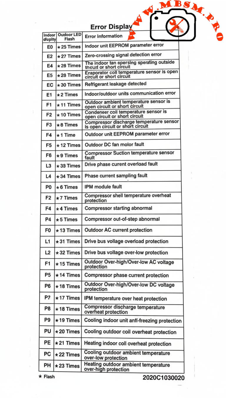
Indoor codes mainly relate to EEPROM parameters, communication, and temperature or refrigerant protection. The table summarizes the key entries from the error‑display list.
| Indoor code | Typical description | Technical meaning |
|---|---|---|
| E0 | Indoor unit EEPROM parameter error | Configuration data in indoor PCB memory cannot be read or is corrupted. |
| E2 | Indoor/outdoor units communication error | Serial data between indoor and outdoor boards lost or unstable. |
| E4 | Indoor room or coil temp sensor error | Temperature sensor open/short, usually T1 or similar designation. |
| E5 | Evaporator coil temperature sensor error | T2 thermistor fault, affecting frost and overheat protection. |
| EC | Refrigerant leakage detected | Control logic detects abnormal combination of coil temperatures and runtime. |
| P9 | Cooling indoor unit anti‑freezing protection | Evaporator temperature too low; system reduces or stops cooling. |
Indoor sensor and communication errors often originate from loose connectors, pinched cables, or water ingress around the PCB rather than failed components, so visual inspection is a critical first step.
Carrier Inverter Outdoor Unit and Power‑Electronics Codes
Outdoor codes in Carrier inverter systems cover ambient and coil sensors, DC fan faults, compressor temperature, current protection, and IPM module errors.
| Code | Short description | Engineering interpretation |
|---|---|---|
| F1 | Outdoor ambient temperature sensor open/short | T4 thermistor fault; affects capacity and defrost logic. |
| F2 | Condenser coil temperature sensor open/short | T3 sensor error; risks loss of condensing control. |
| F3 | Compressor discharge temp sensor open/short | T5 failure; system cannot monitor discharge superheat. |
| F4 | Outdoor EEPROM parameter error | PCB memory error in outdoor unit. |
| F5 | Outdoor DC fan motor fault / speed out of control | DC fan not reaching commanded speed; bearing, driver, or wiring issue. |
| F6 | Compressor suction temperature sensor fault | Suction line thermistor reading abnormal values. |
| F0 | Outdoor AC current protection | Abnormal outdoor current over‑high or over‑low; system enters protection mode. |
| L1 / L2 | Drive bus voltage over‑high / over‑low protection | DC bus outside limits, often due to mains issues or rectifier problems. |
| P0 | IPM module fault | Intelligent Power Module over‑current or internal failure; compressor speed control compromised. |
| P2 | Compressor shell temperature overheat protection | Excessive body temperature at compressor top sensor. |
| P4 | Inverter compressor drive error | Drive IC or gate‑signal abnormal; may follow IPM or wiring problems. |
| P5 | Compressor phase current or mode conflict | Phase current protection or logic conflict in operating mode selection. |
| P6 | Outdoor DC voltage over‑high/over‑low or IPM protection | DC bus or IPM voltage feedback outside safe range. |
| P7 | IPM temperature overheat protection | Inverter module overheating due to high load or blocked airflow. |
| P8 | Compressor discharge temperature overheat protection | Discharge sensor indicates over‑temperature; often linked to poor condenser airflow or charge issues. |
| PU / PE / PC / PH | Coil or ambient overheat / over‑low protections depending on model | Protection of indoor or outdoor coil and ambient sensors during extreme conditions. |
For codes like F0, P0, P1, P6, service manuals stress checking supply voltage, compressor current, and all inverter‑side connections before deciding to replace expensive PCBs or the compressor itself.
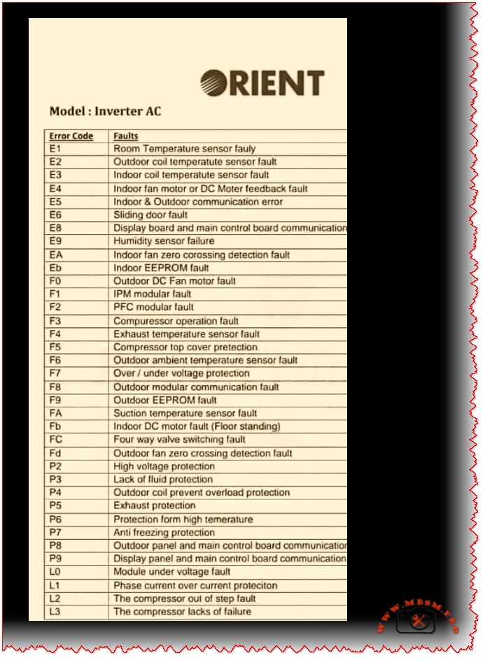
Comparison With LG Inverter Error Logic
Both Carrier and LG inverter systems protect similar components, but the naming and grouping of codes differ slightly.
This comparison helps multi‑brand technicians adapt their diagnostic approach while recognizing common inverter‑system failure modes: sensor faults, communication problems, over‑current, and over‑temperature on the IPM and compressor.
Engineering‑Level Diagnostic Consel for Carrier Inverter AC
Professional troubleshooting of Carrier inverter error codes should follow structured, safety‑oriented steps.
- Stabilize power and reset correctly. Disconnect supply, wait for DC bus capacitors to discharge, and then re‑energize to see if transient grid disturbances caused codes like F0, P1, or L1/L2.
- Measure, don’t guess. For sensor codes (F1–F3, F6, P8, P9), check thermistor resistance vs temperature and compare to tables in Carrier service manuals before replacing parts.
- Check airflow and refrigerant circuit. Overheat protections (P2, P7, P8, PU, PE, PH) frequently point to blocked coils, failed fans, or charge problems rather than electronic failure.
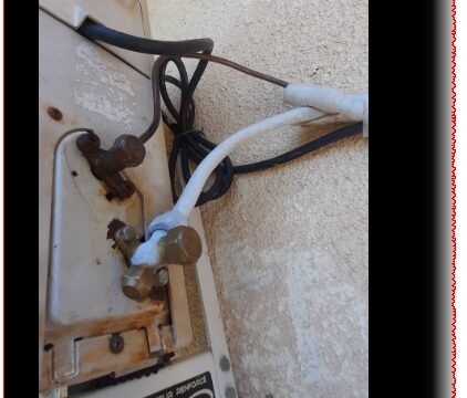
- Handle IPM faults carefully. For P0 and P6, confirm all compressor‑to‑IPM connections, inspect for carbonized terminals, and verify correct insulation before deciding whether the IPM module or compressor has failed.
Following these engineering practices reduces unnecessary part replacement, protects technicians from high DC bus voltages, and helps maintain long‑term reliability of Carrier inverter installations.
Focus keyphrase (Yoast SEO)
Carrier inverter AC error codes indoor outdoor EEPROM sensor communication IPM module fault F0 P0 P6 bus voltage over high over low professional troubleshooting guide
SEO title
Mbsmpro.com, Carrier Inverter AC, Error Codes E0–PH, Indoor and Outdoor Unit, F0 AC Current, P0 IPM Fault, Bus Voltage Protection, Professional HVAC Guide
Meta description
Comprehensive Carrier inverter AC error‑code guide covering indoor and outdoor EEPROM, sensor, communication, F0 current protection, P0 IPM faults, and bus‑voltage alarms, with engineering‑level troubleshooting tips for HVAC technicians.
Slug
carrier-inverter-ac-error-codes-f0-p0-p6-professional-guide
Tags
Carrier inverter error codes, Carrier AC F0 code, Carrier IPM fault P0, EEPROM parameter error, bus voltage protection, inverter air conditioner troubleshooting, HVAC diagnostics, Mbsmgroup, Mbsm.pro, mbsmpro.com, mbsm
Excerpt (first 55 words)
Carrier inverter air conditioners use detailed error codes to protect the compressor, sensors, and inverter electronics. Codes such as E0, F0, P0, and P6 reveal EEPROM faults, outdoor AC current problems, IPM module errors, and DC bus voltage issues, giving HVAC technicians a clear roadmap for safe, accurate troubleshooting and long‑term system reliability.
10 PDF or technical resources about Carrier inverter AC error codes
- Carrier air conditioner error‑code and troubleshooting tables with indoor and outdoor descriptions (E0, F0, P0, P2, etc.).
- Carrier AC error‑code list with explanations for F3, F4, F5, P0–P6 and separate outdoor tables.
- Carrier split‑inverter AC error‑code video and transcript, detailing meanings for E0–E5, F0–F5, P0–P7 and related protections.
- Carrier service manual describing overload current protection and diagnostics for F0 with decision conditions and test steps.
- Carrier mini‑split service documentation covering IPM module errors, bus‑voltage protections, and compressor temperature protections.
- Field‑Masters technical article on F0 error in Carrier split AC, focusing on outdoor current protection causes and fixes.
- Carrier indoor error‑code summary for installers and service technicians (EEPROM, sensor, and communication codes).
- Knowledge‑base article on IPM module faults explaining inspection of connections, refrigerant level, and when to replace the IPM module.
- General inverter error‑code reference for drive boards and IPM protections that parallels Carrier codes, including PH, PL, PU, and over‑current alarms.
- External Carrier code lists used by service centers to cross‑reference outdoor unit errors and recommended corrective actions.
This is exactly the kind of comprehensive information I’ve been looking for. The way you explained the core concepts makes it very easy to follow, even for those who aren’t experts in the field.