
Spot Welding Machine Circuit


Focus Keyphrase
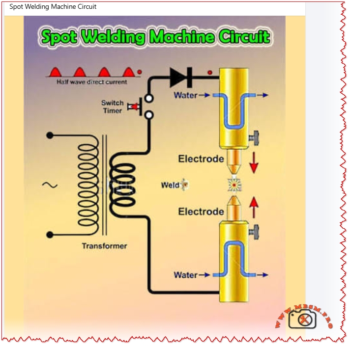
Spot welding machine circuit diagram half wave rectifier transformer timer electrodes water cooled DIY
SEO Title
Mbsmpro.com, Spot Welding Machine Circuit, Half Wave Rectifier, Transformer, Timer, Electrodes, Water Cooled, AC to DC
Meta Description
Explore the spot welding machine circuit with half-wave rectifier, step-down transformer, adjustable timer, and water-cooled electrodes. Detailed diagram breakdown, components, comparisons for DIY builders and pros.
Slug
spot-welding-machine-circuit-diagram-half-wave-rectifier-transformer-timer
Tags
spot welding circuit, welding machine diagram, half wave rectifier, welding transformer, spot welder timer, water cooled electrodes, DIY spot welder, resistance welding, Mbsmgroup, Mbsm.pro, mbsmpro.com, mbsm
Excerpt
Fabricators rely on the classic spot welding machine circuit featuring a half-wave rectifier for reliable AC-to-DC conversion. A heavy-duty step-down transformer boosts current for nugget formation, while an adjustable timer controls squeeze, weld, and hold phases precisely.
Spot Welding Machine Circuit: Complete Breakdown and Build Guide
Workshop pros and DIY enthusiasts build spot welders around a straightforward half-wave rectifier circuit that turns household AC into high-amperage pulses for clean metal joins. This design prioritizes simplicity with water-cooled electrodes to handle heat during extended runs. Transformers step down voltage while ramping current to thousands of amps briefly.
Core Components Table
The rectifier diode handles peak currents up to 500A, feeding the transformer’s low-voltage secondary for nugget fusion in 0.1-1 second bursts.
Circuit Operation Steps
Power flows from AC mains through the half-wave switch to the rectifier diode, producing unidirectional current. This charges the transformer primary, inducing high-current low-voltage output on the secondary side. Timer triggers the cycle: electrodes squeeze sheet metal, current pulses to melt contact point, then hold for solidification. Water lines prevent electrode mushrooming.
Comparison: Half-Wave vs Modern Spot Welder Circuits
Traditional half-wave designs shine for low-cost builds but lag in precision. Check this matchup:
Half-wave rectifier edges out capacitor types for continuous duty on thicker steel (up to 3mm), though full-wave cuts ripple for smoother welds. Inverter MFDC slashes transformer size by 70% but demands complex controls.
Value Comparison Across Builds
Budget spot welders deliver pro results without factory prices. Factor in materials:
Salvage microwave transformers slash costs 80%, paying back in 10 battery pack jobs. Full-wave boosts duty cycle 2x over half-wave for sheet metal shops.
Safety and Troubleshooting Tips
Insulate primaries to avoid shocks; fuse at 30-50A. Monitor electrode force (2-5 kg) to dodge expulsion. Common fixes: replace diode for no DC output, adjust timer pot for short welds. Run cooling water at 2-5 L/min.