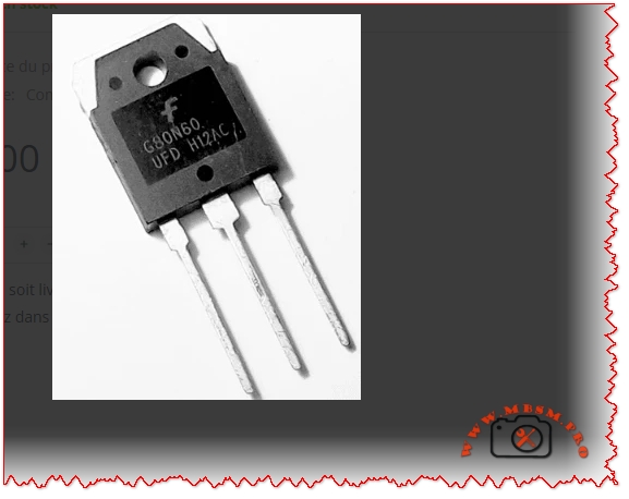
Mbsmpro.com, Transistor IGBT, G80N60UFD, 600 V, 80 A, Ultrafast, TO‑3P, Motor Drive, Inverter, Induction Heating, Welding, UPS, PFC
Overview of the G80N60UFD Ultrafast IGBT 600 V, 80 A
The G80N60UFD is an ultrafast insulated‑gate bipolar transistor (IGBT) designed for high‑efficiency power conversion around 600 V DC buses and up to 80 A collector current.
It uses Fairchild / ON Semiconductor UFD technology with a co‑pack fast recovery diode, optimized for high‑frequency switching, low conduction loss and robust avalanche capability.
For a field technician or design engineer, this component is a solid choice in demanding power stages where classic MOSFETs start to lose efficiency at high voltage and bipolar transistors switch too slowly.
Key Electrical Characteristics of G80N60UFD
The following table summarizes the main parameters typically found in the official datasheet (25 °C, unless noted). Always confirm against the latest datasheet of your specific manufacturer / batch.
| Parameter | Symbol | Typical / Max Value | Notes |
|---|---|---|---|
| Collector‑Emitter Voltage | V<sub>CES</sub> | 600 V | Repetitive, IGBT off |
| Continuous Collector Current @ 25 °C | I<sub>C</sub> | 80 A | With proper heatsink |
| Pulsed Collector Current | I<sub>CP</sub> | >160 A (typ.) | Limited by T<sub>j</sub> |
| Gate‑Emitter Voltage (max) | V<sub>GE</sub> | ±20 V | Never exceed in drive design |
| Collector‑Emitter Saturation Voltage | V<sub>CE(sat)</sub> | ~2.1–2.6 V @ 40–80 A | Strong conduction capability |
| Junction Temperature Range | T<sub>j</sub> | −55 to +150 °C | Industrial class |
| Typical Gate Charge | Q<sub>g</sub> | ~160–200 nC | Important for driver sizing |
| Total Power Dissipation @ 25 °C Case | P<sub>D</sub> | ≈195 W | With ideal heatsink |
| Package Type | – | TO‑3P / TO‑247‑3 | Through‑hole, isolated tab versions exist |
Internal Structure and How the G80N60UFD Works
The IGBT combines:
- A MOSFET gate structure for very high input impedance and easy gate drive.
- A bipolar output section for low on‑state voltage at high current.
In the G80N60UFD, the ultrafast diode is co‑packaged with the IGBT die. This diode clamps inductive energy during free‑wheel phases and is optimized for:
- Low reverse recovery time (t<sub>rr</sub> ≈ tens of ns)
- Low reverse recovery charge (Q<sub>rr</sub>), reducing switching losses and EMI.
This makes the device suitable for switching frequencies typically between 15 kHz and 40 kHz, depending on cooling and losses.
Comparison: G80N60UFD vs. FGH80N60FD vs. Classic 600 V MOSFET
To position the G80N60UFD in a design, it is useful to compare it with a close relative (FGH80N60FD, another 600 V / 80 A field‑stop IGBT) and a generic 600 V MOSFET around 60–70 mΩ R<sub>DS(on)</sub>.
| Feature / Device | G80N60UFD (UFD series) | FGH80N60FD (Field‑stop) | Typical 600 V MOSFET 60–70 mΩ |
|---|---|---|---|
| Device Type | Ultrafast IGBT + Diode | Field‑stop IGBT | Power MOSFET |
| V<sub>CES</sub> / V<sub>DSS</sub> | 600 V | 600 V | 600–650 V |
| I<sub>C</sub> / I<sub>D</sub> (cont.) | 80 A | 80 A | 40–50 A (depending on package) |
| Conduction Loss @ 40–50 A | Low (V<sub>CE(sat)</sub> ≈ 2 V) | Very low (≈1.8 V) | Higher (I × R<sub>DS(on)</sub>) |
| Switching Speed | Very fast (UFD) | Very fast (field‑stop) | Fast but high capacitance |
| Best Frequency Range | 10–30 kHz | 10–30 kHz | Up to 60–80 kHz (lower current) |
| Gate Drive | ±15 V typical | ±15 V typical | 10–12 V typical |
| Ideal Applications | Motor drives, UPS, welding, induction heating | PFC, ESS, telecom, induction heating | SMPS, PFC, lower power drives |
Engineering conclusion:
At 80 A level and 600 V bus, the G80N60UFD offers better efficiency and robustness than many single MOSFETs, especially in applications where conduction loss dominates. The FGH80N60FD is a newer field‑stop variant with slightly lower V<sub>CE(sat)</sub>, but in many real installations the difference is small compared with cooling and PCB layout quality.
Typical Applications for G80N60UFD 600 V, 80 A
Because of its fast switching and strong current capability, this device is widely used in:
- AC and DC motor drives (industrial motors, pumps, fans, compressors).
- Inverter stages of solar, UPS, and battery storage systems with 300–400 V DC buses.
- Induction heating and welding machines where rapid current commutation is necessary.
- High‑power SMPS and PFC stages up to several kilowatts.
- Servo controls and robotics requiring efficient torque control.
Practical Gate Drive and Protection Considerations
Recommended Gate Drive Strategy
| Parameter | Typical Design Value | Comment |
|---|---|---|
| Gate drive voltage | +15 V ON, 0 V or −5 V OFF | Negative off‑bias improves immunity |
| Gate resistor R<sub>G</sub> | 5–15 Ω | Balance of dV/dt, EMI, losses |
| Gate driver type | Isolated driver with Miller clamp | For safe high‑side / low‑side control |
| Desaturation / over‑current sense | Recommended | Rapid fault turn‑off |
| Gate‑emitter Zener clamps | 18–20 V | Protect gate from surges |
Using too small a gate resistor may reduce switching losses but increases dV/dt and EMI, and can push the device into unsafe operating areas. Field experience shows that a compromise around 8–12 Ω works well for most industrial inverters.
Thermal Design and Heatsink Selection
IGBTs at this power level must be treated as thermal devices as much as electrical ones.
Approximate thermal path:
- Junction‑to‑case R<sub>θJC</sub> ≈ 0.6–0.7 °C/W
- Case‑to‑heatsink (with proper thermal grease and insulation) ≈ 0.2–0.3 °C/W
- Heatsink‑to‑ambient R<sub>θSA</sub> chosen for required temperature rise
Example design thought:
If the G80N60UFD is expected to dissipate 60 W average, and the maximum ambient is 40 °C, you want junction temperature below 125 °C for reliability:
- Allowed ΔT<sub>JA</sub> ≈ 125 – 40 = 85 °C
- Required total R<sub>θJA</sub> = 85 / 60 ≈ 1.4 °C/W
Subtracting R<sub>θJC</sub> + R<sub>θCS</sub> (~1.0 °C/W) gives ≈0.4 °C/W for the heatsink. This means a large finned heatsink, often with forced air for continuous high‑load operation.
Example Application Schematic: Single‑Phase Inverter Leg Using G80N60UFD
Below is a simplified textual schema style you can graphically reproduce in your WordPress article:
- DC Bus: 325–400 V from rectified mains or battery bank
- Upper Switch (Q1): G80N60UFD
- Lower Switch (Q2): G80N60UFD
- Freewheel Diodes: co‑pack diodes in each IGBT, no extra ultrafast diode normally needed
- Gate Driver: high‑side/low‑side driver IC with isolated supply (for example 15 V).
- Snubber Network: RC or RCD across each IGBT (e.g., 100 nF / 1–2 kΩ / 600 V film capacitor)
- Current Sense: shunt resistor or Hall sensor on the DC bus or emitter leg.
- Control: Microcontroller or DSP generating complementary PWM with dead‑time (200–500 ns).
This half‑bridge cell can be duplicated to create:
- Three‑phase motor drives.
- Full‑bridge inverters for UPS or photovoltaic systems.
- Push‑pull or full‑bridge induction heating converters.
Comparison of G80N60UFD With Lower‑Power IGBT Devices
For designers stepping up from smaller IGBTs, the following table shows why the G80N60UFD is in a different league.
| Parameter | 30 A / 600 V IGBT (generic) | 50 A / 600 V IGBT (generic) | G80N60UFD 80 A / 600 V |
|---|---|---|---|
| Continuous current | 30 A | 50 A | 80 A |
| Peak current capability | ~60 A | ~100 A | ≥160 A |
| Recommended max power stage | <2 kW | 2–3 kW | 3–6 kW or more |
| V<sub>CE(sat)</sub> at nominal current | ≈2.2–2.5 V | ≈2.2–2.5 V | Comparable or slightly lower |
| Package | TO‑220 or TO‑247 | TO‑247 | TO‑3P / TO‑247‑3 large tab |
| Cooling requirement | Medium | Medium‑high | High, usually forced air |
When your application moves beyond about 3 kW at 230 V AC, investing in G80N60UFD‑class devices plus serious thermal management is normally more economical than paralleling several smaller IGBTs.
Installation Tips, Field Notes and Reliability Advice
From a practical maintenance and design point of view, these points can make the difference between a reliable inverter and a burner of semiconductors:
- Respect dV/dt limits
Fast devices like the G80N60UFD generate steep voltage transitions. Keep loop area small (short bus bars, wide copper), and use proper snubber networks to limit overshoot. - Gate drive layout
Route gate and emitter (return) traces as a twisted pair or very close tracks. A shared emitter path with power current causes false turn‑on through Miller capacitance. - Heatsink and mounting
- Use a flat, clean surface, thin thermal compound, and correct screw torque.
- Consider insulating pads if the collector tab must be isolated from chassis.
- After mounting, always check for shorts between tab and heatsink with a megohmmeter.
- Current sharing if paralleled
Parallel use is possible but requires careful design: equal gate resistors, matched wiring lengths, shared heatsink, and sometimes small emitter resistors to encourage current balancing. - EMI compliance
Use common‑mode chokes, proper shielding, and LC filters on the mains or DC input. A badly filtered high‑power IGBT bridge can exceed EMC limits easily. - Protection coordination
Combine fast electronic protection (desaturation, overcurrent, over‑temperature) with slower fuses or circuit breakers. A fuse alone is not fast enough to save an IGBT at 80 A.
Advantages and Practical Benefits of Using G80N60UFD
- Higher efficiency in medium‑frequency power converters compared with slower IGBTs and many high‑voltage MOSFETs.
- Integrated ultrafast diode reduces component count and PCB area.
- Robust structure tolerates industrial environments and transient conditions when properly designed.
- Good compromise between conduction loss and switching loss, ideal for inverters running around 16–20 kHz.
For HVAC compressors, industrial pumps and fans, welding machines, induction cookers or heaters, upgrading an older design to G80N60UFD‑class devices often results in:
- Lower operating temperature of the power stage.
- Better efficiency (sometimes several percentage points).
- Increased reliability and longer service intervals.
Design Recommendations and Professional Advice
- Start from the datasheet safe operating area (SOA).
Do not design only from RMS current. Check short‑circuit withstand time, repetitive peak current, and switching SOA. - Simulate first, verify later.
Use SPICE or vendor models for G80N60UFD (or SGH80N60UFD / FGH80N60FD equivalents) to simulate switching losses and junction temperature over a complete load cycle. - Always measure in the real system.
A good differential probe and current clamp are essential to verify waveforms, dV/dt, and peak currents. Adjust gate resistors and snubbers based on real measurements, not only theoretical calculations. - Plan for serviceability.
Place IGBTs on easily accessible heatsink areas, label them clearly, and keep some mechanical margin so modules can be replaced without damaging PCB traces. - Document thermal and electrical limits in the maintenance manual.
Technicians must know maximum current, duty cycle, and temperature targets. This reduces the risk of field modifications that push devices out of their safe area.
Focus Keyphrase (≤191 characters)
G80N60UFD IGBT 600 V 80 A ultrafast transistor, TO‑3P power switch for motor drive, inverter, induction heating, welding, UPS, PFC and high‑efficiency industrial converters
SEO Title
G80N60UFD IGBT 600 V, 80 A – Ultrafast Power Transistor for Motor Drives, Inverters, Induction Heating and Welding | Mbsmpro.com
Meta Description
A detailed engineering guide to the G80N60UFD 600 V, 80 A ultrafast IGBT. Characteristics, comparison with other 600 V devices, thermal design, gate drive, inverter schematics, and professional tips for reliable industrial power stages.
Slug
g80n60ufd-igbt-600v-80a-ultrafast-transistor-to-3p
Tags
G80N60UFD, 600V IGBT, 80A IGBT, ultrafast IGBT transistor, TO-3P power transistor, motor drive inverter, induction heating IGBT, welding inverter IGBT, UPS PFC switch, power electronics design, gate driver design, thermal management IGBT, industrial converter, Mbsmgroup, Mbsm.pro, mbsmpro.com, mbsm
Excerpt (first 55 words)
The G80N60UFD is an ultrafast 600 V, 80 A insulated‑gate bipolar transistor in a robust TO‑3P package, designed for high‑efficiency industrial inverters. Combining MOSFET‑like gate control with low saturation voltage and a co‑pack fast recovery diode, it is ideal for motor drives, induction heating, welding machines, UPS and PFC stages.