SCE SCOOP


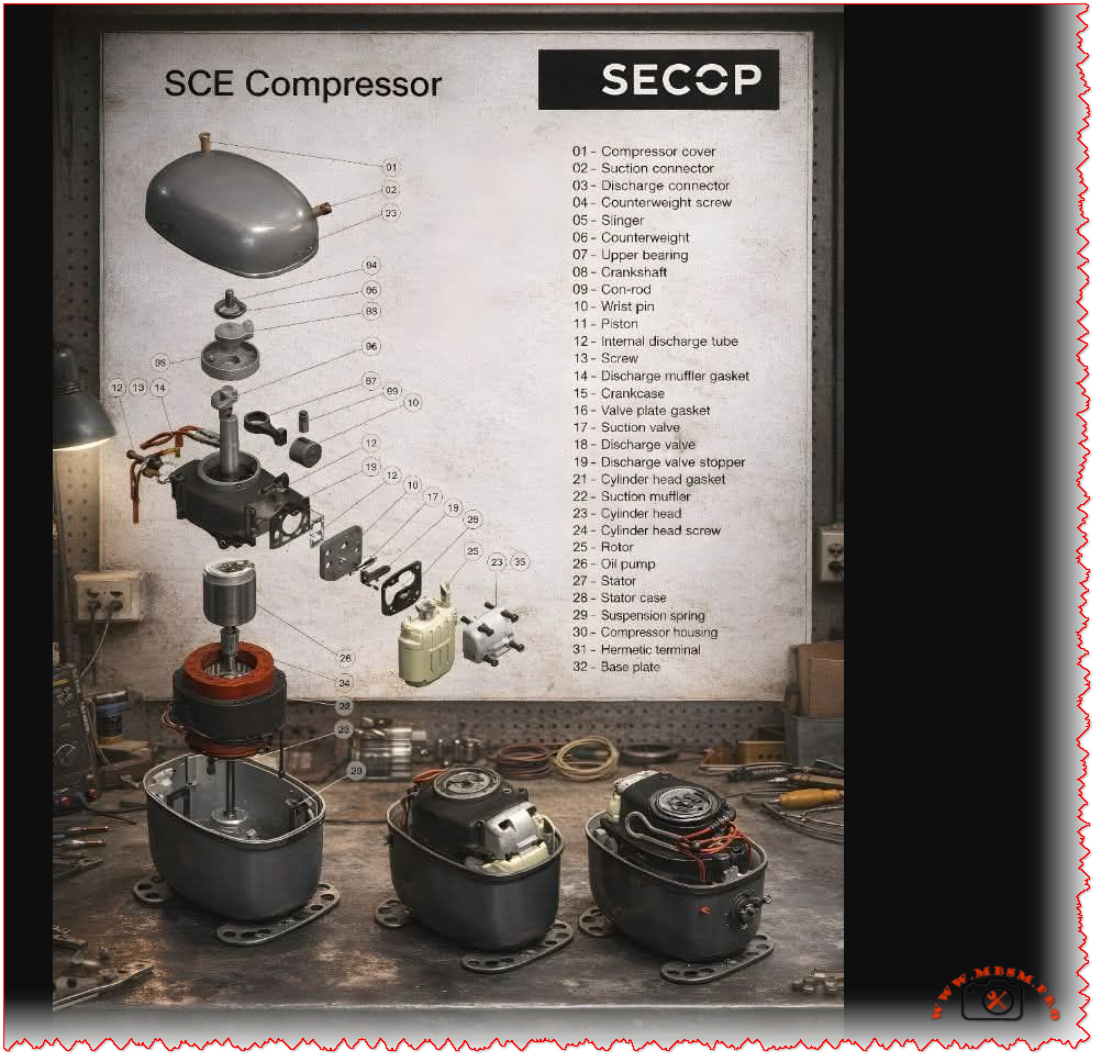
Inside the SECOP SCE Hermetic Compressor: A Complete Exploded View and Parts Identification Guide
For technicians, engineers, and procurement specialists in the commercial refrigeration industry, understanding the internal anatomy of a compressor is not just academic—it’s essential for efficient maintenance, accurate troubleshooting, and reliable sourcing of spare parts. The SECOP SCE series hermetic compressor is a cornerstone in many refrigeration systems, known for its durability and performance. This article provides a comprehensive, journalistic breakdown of its internal components using a detailed exploded view, serving as your definitive visual and technical guide.
Decoding the Exploded View: A Systematic Walkthrough
An exploded view diagram is more than just a parts list; it’s a roadmap to the machine’s soul. It shows how individual components interact within the sealed “hermetic” shell, where the motor and compressor are welded shut to protect against refrigerant and moisture. Let’s navigate the key assemblies revealed in the SCE compressor diagram.
1. The Core Compression Assembly
This is the heart of the compressor, where mechanical motion translates into refrigerant compression.
- Piston (11) & Cylinder (Part of Crankcase 15): The piston moves within the cylinder bore, creating the vacuum and pressure cycles.
- Crankshaft (8): Driven by the motor, its rotational motion is converted into the piston’s reciprocating motion via the connecting rod (9) and wrist pin (10).
- Valve System: This critical assembly manages refrigerant flow. The suction valve (17) opens to draw in low-pressure gas. The discharge valve (18), held by its stopper (19), opens to release high-pressure gas into the discharge muffler.
2. The Electrical & Drive Assembly
Nestled beneath the compressor, this assembly powers the entire system.
- Stator (27): The stationary part of the electric motor, containing copper windings, housed inside the stator case (28).
- Rotor (25): Pressed onto the crankshaft (8), it rotates within the stator’s magnetic field.
- Hermetic Terminal (31): The vital electrical pass-through that allows power cables to enter the sealed compressor housing without leaking refrigerant.
3. Structural & Ancillary Components
These parts provide support, balance, and necessary functionalities.
- Compressor Housing (30): The iconic welded steel shell that contains all components.
- Suspension Springs (29): Isolate vibrations, preventing noise and wear from transmitting to the refrigeration cabinet.
- Oil Pump (26): Often a centrifugal type on the crankshaft, it ensures critical lubrication reaches the upper bearing (7) and other moving parts.
- Counterweight (6): Balances the rotating assembly to minimize vibration, secured by a screw (4) and sometimes accompanied by a slinger (5).
Complete SECOP SCE Compressor Parts Reference Table
For quick reference and cross-referencing with part numbers, here is a complete table of the components identified in the exploded view:
| Item No. | Part Name | Primary Function |
|---|---|---|
| 01 | Compressor Cover | Protects internal parts, forms suction chamber |
| 02 | Suction Connector | Inlet for low-pressure refrigerant gas |
| 03 | Discharge Connector | Outlet for high-pressure refrigerant gas |
| 04 | Counterweight Screw | Secures the counterweight to the crankshaft |
| 05 | Slinger | Assists in oil distribution |
| 06 | Counterweight | Balances rotating assembly to reduce vibration |
| 07 | Upper Bearing | Supports the top of the rotating crankshaft |
| 08 | Crankshaft | Converts motor rotation into piston movement |
| 09 | Connecting Rod | Links the crankshaft to the piston |
| 10 | Wrist Pin | Pivot point connecting piston and connecting rod |
| 11 | Piston | Compresses refrigerant within the cylinder |
| 12 | Internal Discharge Tube | Channels compressed gas to the muffler |
| 13 | Screw | Fastens various components (e.g., muffler) |
| 14 | Discharge Muffler Gasket | Seals the discharge muffler connection |
| 15 | Crankcase | Main body housing cylinders and crankshaft |
| 16 | Valve Plate Gasket | Seals between crankcase and valve plate |
| 17 | Suction Valve | One-way valve for refrigerant intake |
| 18 | Discharge Valve | One-way valve for refrigerant outlet |
| 19 | Discharge Valve Stopper | Limits discharge valve movement |
| 21 | Cylinder Head Gasket | Seals the cylinder head |
| 22 | Suction Muffler | Reduces noise from suction gas pulsation |
| 23 | Cylinder Head | Covers the cylinder, part of compression chamber |
| 24 | Cylinder Head Screw | Secures the cylinder head |
| 25 | Rotor | Rotating part of the electric motor |
| 26 | Oil Pump | Circulates oil for lubrication |
| 27 | Stator | Stationary electromagnetic part of the motor |
| 28 | Stator Case | Holds and positions the stator |
| 29 | Suspension Spring | Vibration isolation mounting |
| 30 | Compressor Housing | Main hermetic (sealed) outer shell |
| 31 | Hermetic Terminal | Electrical connection into sealed housing |
| 32 | Base Plate | Foundation for internal assembly mounts |
Why This Knowledge Matters for Your Business
Whether you’re a technician diagnosing a faulty discharge valve or a sourcing manager looking for a genuine SECOP crankshaft, this visual guide empowers you with precision. Correct part identification:
- Reduces Downtime: Enables faster, accurate diagnosis.
- Ensures Compatibility: Guarantees replacement parts match the exact SCE model specifications.
- Promotes Effective Communication: Allows clear reference between teams, suppliers, and clients.