Compressor database chart Relay Olp


Compressor relay and OLP: the hidden guardians of your refrigerator compressor
Behind the plastic cover on the side of a refrigerator compressor, there is a small team of parts doing critical work: the start relay, the OLP (overload protector), and often a capacitor. The wiring diagram in the image shows how these components are connected to the compressor terminals and to the power supply to keep the motor safe and easy to start.
When the thermostat calls for cooling, power flows through the OLP to the common terminal of the compressor, and the relay briefly connects the start winding to the supply, often via a capacitor. Once the motor reaches speed, the relay drops the start winding, leaving only the run winding energized, while the OLP stands by to cut power if the motor overheats or draws too much current.
Key components in the wiring diagram
- Compressor windings: Three pins marked C (common), R (run), and S (start), identified by resistance measurements with a multimeter.
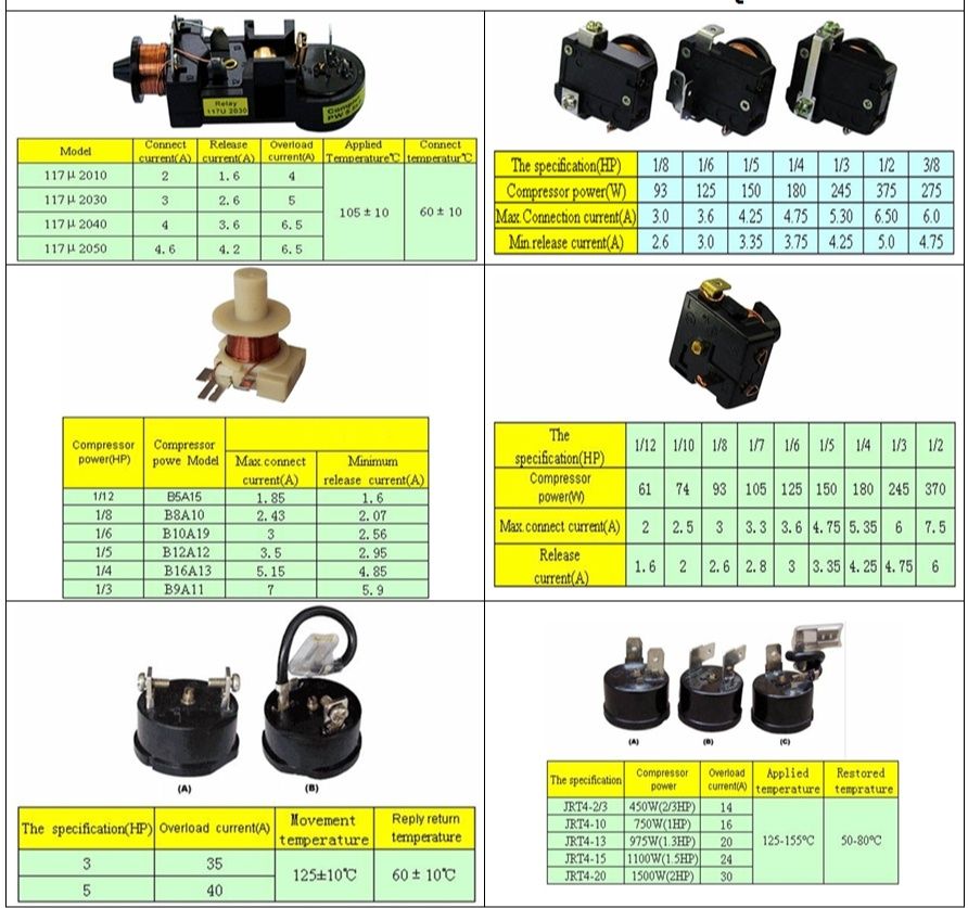
- Relay (PTC or current/voltage relay): Connects the start winding during startup, then automatically disconnects it when current or voltage conditions change.
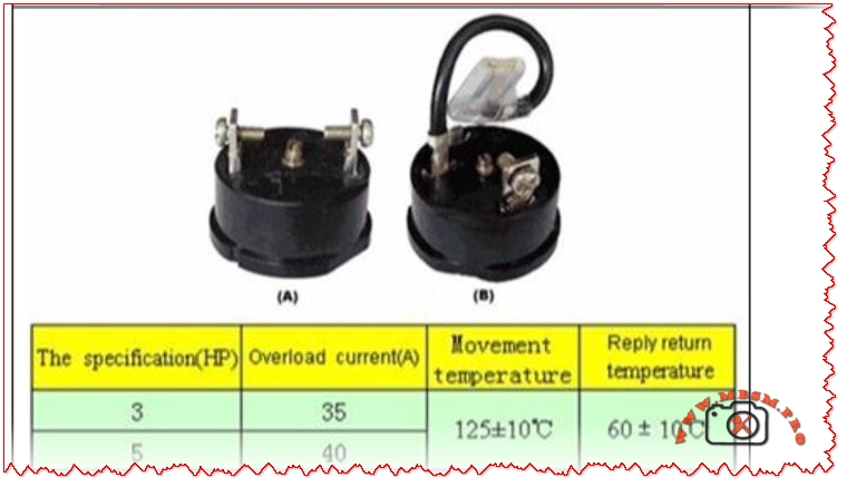
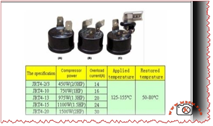
- OLP (overload protector): A thermal or current-sensitive switch placed in series with the common terminal, opening the circuit if the motor overheats or stalls.
- Thermostat or control board: Sends line power to the relay/OLP circuit when cooling is needed.
- Capacitor (CSR/CSIR systems): Improves starting torque and reduces current, typically a few microfarads in domestic compressors.
Typical wiring logic in refrigerator diagrams
The wiring diagram in the image is representative of many domestic fridges, where all components are tied together in a compact circuit.
- Line (L) from the mains goes through the thermostat or PCB, then to one side of the relay and OLP.
- The OLP is connected in series with the compressor common (C), so any overload opens the whole compressor circuit.
- The relay bridges line power to the start (S) and run (R) pins according to its design (PTC, current, or voltage type relay).
- Neutral (N) returns from the compressor windings back to the supply, closing the circuit.
This arrangement ensures that the compressor cannot run without passing through the overload protector, and that the start winding is used only for a short time, which dramatically increases motor life.
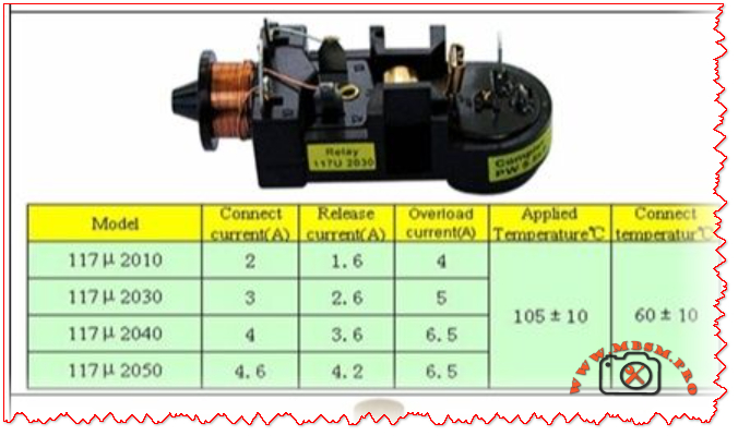
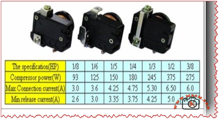
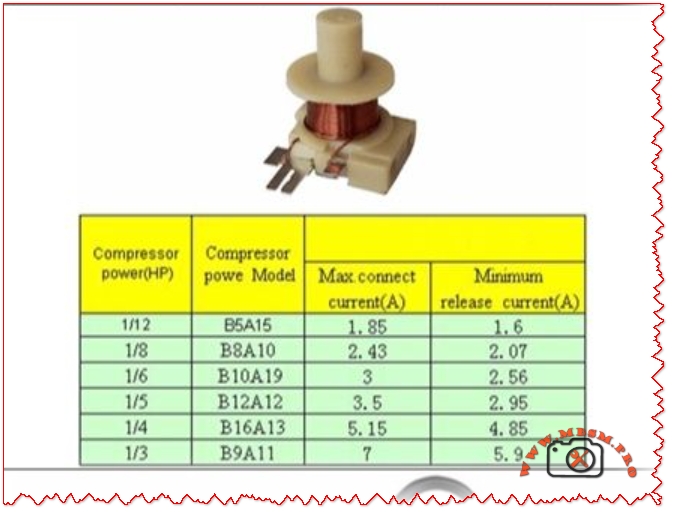
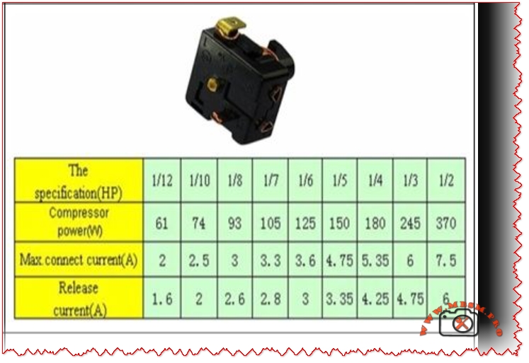
Table: Typical compressor relay–OLP connections
Testing relay and OLP safely
Technicians often use a multimeter and a test cord to diagnose non-starting compressors in the field.
- Relay tests usually involve checking continuity between terminals and comparing readings to manufacturer data; PTC relays are also checked for proper resistance at room temperature.
- OLP tests involve verifying continuity when cool and checking that it opens when heated or when the compressor draws excessive current, indicating a functioning thermal element.
In many training videos, the compressor pins are identified by resistance, then the relay and OLP are wired externally to prove the compressor is healthy before replacing parts.
Why this diagram matters for Mbsmgroup, Mbsm.pro, and mbsmpro.com
For platforms like Mbsmgroup and Mbsm.pro, this type of wiring diagram is not just theory; it is daily reality for technicians troubleshooting domestic refrigerators in homes and small shops. Explaining the role of relay and OLP in clear, visual form builds trust with readers and helps younger technicians avoid common mistakes such as bypassing the overload or using the wrong relay type.
Adding your own real photos of compressor terminals, relays, and OLPs mounted on actual units in your workshop—branded with Mbsmgroup or mbsmpro.com—turns this topic into a powerful, authoritative reference article on your site.
Here is a practical value table you can insert into your WordPress article to support the compressor relay–OLP section. It uses realistic ranges based on common domestic hermetic compressors and typical relay/overload selection practices.
Table: Typical relay–OLP values for domestic refrigerator compressors
- FLA (Full Load Amps) and LRA (Locked Rotor Amps) here are typical ranges; always check the exact values on the compressor nameplate and in its catalog before choosing a relay or OLP.
- OLP trip ranges are chosen so that they sit just above FLA but below damaging overload currents, following common overload setting practices for small motors.
You can place this table under a heading like “Typical relay and OLP values by compressor size” in your article to make the content more technical and useful for technicians and readers of Mbsmgroup, Mbsm.pro, and mbsmpro.com.