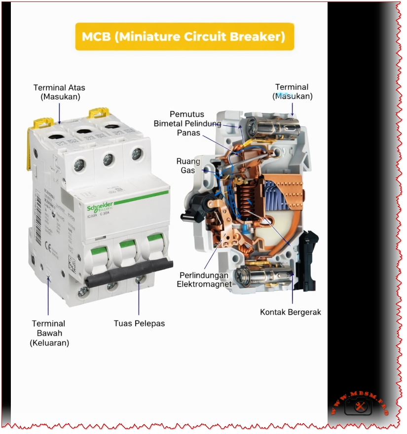
MCB (Miniature Circuit Breaker): Complete Guide to Thermal Magnetic Protection Technology
FOCUS KEYPHRASE (Max 191 characters)
MCB miniature circuit breaker thermal magnetic protection mechanism bimetallic overload short circuit electrical safety
META DESCRIPTION (155-160 characters)
Discover how MCB miniature circuit breakers work with thermal-magnetic protection. Complete technical guide to overload and short-circuit safety mechanisms.
SEO SLUG (URL-friendly)
mcb-miniature-circuit-breaker-thermal-magnetic-protection-guide
EXCERPT (First 55 words)
An MCB (Miniature Circuit Breaker) is an automatic electrical switch that protects circuits from overloads and short circuits. Using dual thermal-magnetic mechanisms, MCBs detect abnormal currents and instantly disconnect power to prevent equipment damage and fire hazards. Compact, reliable, and essential for modern electrical safety.
TAGS (Separated by commas)
MCB, Miniature Circuit Breaker, thermal-magnetic protection, bimetallic strip, electrical safety, circuit protection, overload protection, short circuit, electrical equipment, Mbsmgroup, Mbsmpro.com, mbsm.pro, mbsm, electrical systems, home wiring, industrial protection
MCB (Miniature Circuit Breaker): The Complete Technical Guide to Thermal-Magnetic Protection
Introduction: What is an MCB?
An MCB (Miniature Circuit Breaker) represents one of the most critical innovations in electrical safety systems. This automatic protective device safeguards residential, commercial, and industrial electrical installations by instantly interrupting power flow when dangerous conditions occur. Unlike traditional fuses that require replacement, modern MCBs offer reusable, reliable protection through intelligent dual-mechanism technology.
The primary function of an MCB is straightforward yet vital: detect abnormal electrical conditions and automatically isolate the circuit before damage occurs. Whether protecting a household appliance or industrial machinery, MCBs serve as the first line of defense against electrical hazards.
How MCB Works: Understanding the Dual Protection System
The Thermal Protection Mechanism
The thermal component of an MCB employs a sophisticated bimetallic strip—a thin metal band created by bonding two different metals together. These metals possess different thermal expansion coefficients, meaning they expand at different rates when heated.
The thermal process operates as follows:
- Normal Operation – Under rated current conditions, heat generation is minimal. The bimetallic strip remains relatively straight.
- Overload Detection – When current exceeds the MCB’s rated capacity, excessive heat causes unequal expansion between the two bonded metals.
- Strip Deflection – The differential expansion forces the bimetallic strip to bend or curve progressively.
- Mechanical Latch Release – Once the strip bends sufficiently, it physically releases a mechanical latch mechanism.
- Contact Separation – The released latch triggers the operating mechanism to open the electrical contacts, stopping current flow.
Key Characteristic: Thermal protection provides delayed response, making it ideal for sustained overload situations lasting seconds to minutes.
The Magnetic Protection Mechanism
While thermal protection handles gradual overloads, magnetic protection addresses immediate threats from short circuits.
Inside each MCB exists a solenoid coil (electromagnet) that surrounds the electrical contacts. When current flows normally, the magnetic field strength remains insufficient to trigger action.
The magnetic response sequence:
- Short Circuit Occurrence – A fault suddenly causes current to spike to dangerous levels (often 10-100 times the rated current).
- Magnetic Field Generation – The solenoid coil creates an intense electromagnetic field proportional to current magnitude.
- Armature Attraction – This powerful magnetic field attracts an armature (movable iron piece) at lightning speed.
- Instant Contact Opening – The armature movement triggers an override mechanism that forces electrical contacts open within milliseconds.
- Arc Suppression – Specialized components called arc contacts and gas-filled chambers extinguish any electrical arc that forms during contact separation.
Key Characteristic: Magnetic protection provides instantaneous response (typically 10-50 milliseconds), protecting against catastrophic short-circuit damage.
Technical Specifications: Understanding MCB Parameters
Current Rating Standards
MCBs come in standardized current ratings, each suited to specific applications:
| MCB Rating (Amperes) | Typical Application | Common Use |
|---|---|---|
| 0.5A – 2A | High-sensitivity circuits | Lighting, low-power sensors |
| 3A – 6A | General lighting circuits | Residential household lighting |
| 10A – 13A | Standard domestic circuits | Appliances, outlets, general power |
| 16A – 20A | Heavy-duty domestic use | Kitchen appliances, water heaters |
| 25A – 32A | Industrial and commercial | Industrial machinery, heavy loads |
| 40A – 63A | Large installations | Industrial production lines |
| 80A – 125A | Main distribution systems | Building main switchboards |
Expert Recommendation: Select MCB ratings based on wire gauge and actual load requirements, not convenience. Undersized MCBs trip frequently; oversized units provide inadequate protection.
Voltage Specifications
MCBs operate within defined voltage ranges:
- Single-Phase MCBs: 230V (standard residential in most countries)
- Three-Phase MCBs: 400V (industrial applications)
- Dual-Voltage Models: Can operate at both 230V and 400V
Breaking Capacity (Interrupting Rating)
This critical specification indicates the maximum short-circuit current an MCB can safely interrupt without sustaining damage. Measured in kiloamperes (kA), breaking capacity values typically range from 3 kA to 25 kA:
| Breaking Capacity | Application Suitability | Typical Environment |
|---|---|---|
| 3 kA – 6 kA | Lightweight residential use | Modern suburban homes, low-fault areas |
| 10 kA | Standard domestic/commercial | Typical apartment buildings, offices |
| 15 kA – 25 kA | Industrial and high-fault areas | Factories, power-dense facilities |
Critical Safety Note: Never install an MCB with insufficient breaking capacity for your electrical system’s fault level. Exceeding breaking capacity causes dangerous failure.
MCB Curve Types: Matching Protection to Application
MCBs employ different tripping characteristics, designated by letters B, C, and D. Each curve represents how quickly the MCB responds to different multiples of rated current:
Type B Curve MCBs
- Magnetic Trip Threshold: 3–5 times rated current
- Optimal For: Purely resistive loads with minimal inrush current
- Applications: Incandescent lighting, resistive heaters, general residential wiring
- Response Time: Fast, but slightly delayed for transient spikes
Type C Curve MCBs (Most Common in Residential/Commercial)
- Magnetic Trip Threshold: 5–10 times rated current
- Optimal For: Mixed loads with moderate inrush currents
- Applications: Standard household circuits, office equipment, small motors, the most versatile choice
- Response Time: Balanced between nuisance tripping and protection
- Industry Standard: Nearly universal choice for general-purpose installations
Type D Curve MCBs
- Magnetic Trip Threshold: 10–20 times rated current
- Optimal For: Loads with high inrush currents
- Applications: Large motors, transformers, industrial machinery, welding equipment, compressors
- Response Time: More forgiving of startup transients, essential for heavy industrial loads
Comparison Table: MCB Curve Selection
| Characteristic | Type B | Type C | Type D |
|---|---|---|---|
| Magnetic Sensitivity | Very High (3–5×) | Medium (5–10×) | Low (10–20×) |
| Residential Use | Specific applications | General standard | Rare |
| Commercial Use | Limited | Standard | Industrial |
| Motor Protection | Poor | Fair | Good |
| Inrush Tolerance | Minimal | Moderate | High |
| Cost | Low | Low | Moderate |
| Reliability | Good | Excellent | Good |
Thermal vs. Magnetic Protection: Complementary Systems
The brilliance of MCB design lies in combining these two protection mechanisms, each handling distinct fault scenarios:
When Does Thermal Protection Activate?
Thermal protection engages during gradual overload conditions:
- Current exceeds rated value but remains below magnetic threshold
- Heat gradually accumulates in the bimetallic strip
- Activation Time: 5 seconds to several minutes depending on overload magnitude
- Examples: Running multiple high-power appliances simultaneously, undersized circuits carrying sustained excess load
When Does Magnetic Protection Activate?
Magnetic protection engages during sudden, catastrophic faults:
- Current spikes instantly to dangerous levels (short circuits, direct faults)
- Electromagnetic field builds instantly
- Activation Time: 10–50 milliseconds (near-instantaneous to human perception)
- Examples: Touching live wires, equipment short circuits, electrical arcing, damaged insulation allowing conductors to contact each other
Synergistic Protection Table
| Scenario | Thermal Response | Magnetic Response | Outcome |
|---|---|---|---|
| Overloaded circuit (sustained) | ✓ TRIGGERS | – Remains inactive | MCB trips safely |
| Short circuit (sudden) | – Inactive | ✓ TRIGGERS | Instant protection |
| High inrush current (motor start) | – Tolerates | – Tolerates (if Type C/D) | No false trips |
| Combination overload + fault | ✓ TRIGGERS | ✓ TRIGGERS | Redundant protection |
MCB vs. MCCB: Understanding the Key Differences
Confusion often arises between MCBs and MCCBs (Molded Case Circuit Breakers). While both protect circuits, they serve fundamentally different applications:
Comprehensive Comparison Table
| Parameter | MCB (Miniature) | MCCB (Molded Case) |
|---|---|---|
| Current Capacity | Up to ~125A | 10A to 2,500A+ |
| Size | Compact (17.5mm per pole) | Large, robust housing |
| Interrupting Rating | 3–25 kA typical | 10,000–200,000 kA |
| Trip Mechanism | Fixed thermal-magnetic | Thermal-magnetic + electronic |
| Adjustment Options | No | Full adjustability available |
| Application | Residential, small commercial | Industrial, high-demand facilities |
| Cost | €2–10 per unit | €50–500+ per unit |
| Installation Simplicity | Plug-and-play, DIN-rail mount | Requires specialized installation |
| Maintenance | Minimal | Regular calibration necessary |
| Protection Types | Overload + short circuit | Overload + short circuit + ground fault |
| Suitable For | Homes, offices, retail | Factories, hospitals, data centers |
Decision Matrix: Choosing Between MCB and MCCB
Choose MCB When:
- Current requirements remain below 100A
- Cost consciousness is important
- Simple, maintenance-free operation is desired
- Space in electrical panels is limited
- Application is residential or small commercial
Choose MCCB When:
- Current demand exceeds 100A
- Fine-tuned protection adjustment is necessary
- Equipment cost justifies enhanced protection
- Ground fault detection is critical
- Industrial or mission-critical application
Internal Architecture: Component Deep-Dive
Bimetallic Strip Composition
The bimetallic strip typically consists of:
- Steel Component – Higher thermal expansion coefficient, expands readily with heat
- Brass/Copper Alloy Component – Lower thermal expansion coefficient, resists expansion
When bonded together and heated, differential expansion forces the assembly to curve. This design allows precise calibration: engineers adjust strip thickness, length, and material composition to achieve exact trip temperatures for specific current ratings.
Solenoid Coil Specifications
The electromagnet comprises:
- Copper Wire Winding – Typically 500–1,000 turns depending on design
- Soft Iron Core – Concentrates magnetic field for maximum strength
- Precise Calibration – Coil parameters engineered to trigger at exact current multiples
Electrical Contacts
MCBs employ specialized contacts:
- Main Contacts – Silver-plated for electrical conductivity and corrosion resistance
- Arc Contacts – Harder metals (tungsten or molybdenum) that resist electrical erosion
- Arc Suppression Chamber – Quartz sand or gas chamber that cools and extinguishes arcs during contact separation
- Contact Material Longevity – Typically 10,000+ mechanical operations before replacement consideration
Installation Best Practices: Expert Recommendations
Critical Safety Considerations
1. Proper Circuit Protection Coordination
MCBs must be strategically sized:
| Consideration | Guideline | Rationale |
|---|---|---|
| Wire Gauge Matching | MCB rating ≤ wire ampacity | Prevents wire overheating before MCB trips |
| Selective Coordination | Downstream MCBs trip first | Isolates faults to affected circuit only |
| Load Calculation | Sum actual amperes + 25% safety margin | Accounts for seasonal variations, equipment aging |
2. Ambient Temperature Compensation
MCB performance varies with temperature:
- High Temperatures (>40°C): Thermal element becomes more sensitive; may trip prematurely on normal loads
- Low Temperatures (<20°C): Reduced sensitivity may delay thermal tripping
- Solution: Select MCBs with ambient temperature ratings appropriate for installation environment
3. Curve Selection Validation
Test inrush currents before installation:
- Measure startup currents of motors and transformers
- Compare against MCB curve trip thresholds
- Ensure adequate margin to prevent nuisance tripping
Installation Sequence
- Power Isolation – Ensure main supply disconnection and lockout/tagout procedures
- DIN-Rail Preparation – Install on properly grounded DIN rail at 35mm width nominal
- Conductor Termination – Use appropriate cable terminals; maintain contact pressure specifications
- Clearance Verification – Ensure minimum 25mm clearance between pole terminals
- Labeling – Permanently mark circuit identification on MCB or adjacent labeling
- Testing – Verify manual trip mechanism and test circuit integrity before energization
Common MCB Failures: Diagnosis and Prevention
Premature or Nuisance Tripping
Symptom: MCB repeatedly trips without apparent overload
Possible Causes:
- Undersized MCB for actual circuit load
- Inrush current from motor/transformer exceeding Type C tolerance
- Moisture infiltration or environmental stress
- Internal mechanical wear after years of service
Solutions:
- Calculate actual circuit load accurately and upsize appropriately
- Switch to Type D MCB if high-inrush loads present
- Ensure panel installation in dry, temperature-controlled environment
- Replace MCB if mechanical wear suspected
Failure to Trip (Safety Hazard)
Symptom: Dangerous overload or short circuit occurs without MCB response
Possible Causes:
- Undersized breaking capacity for fault current level
- Contact welding from arc damage
- Mechanical jamming or corrosion
- Electromagnetic coil failure
Critical Action: Immediately disconnect circuit and replace MCB. This represents serious safety risk.
Thermal Drift or Inconsistent Performance
Symptom: MCB trips at different current levels depending on temperature or recent history
Possible Causes:
- Bimetallic strip metal fatigue from repeated heating cycles
- Environmental temperature extremes affecting thermal sensitivity
- Interaction between thermal and magnetic mechanisms during simultaneous stress
Resolution: Replacement with fresh MCB or upgrade to premium models with enhanced thermal stability.
Advantages of Modern MCB Technology
Superior Safety Profile
✓ Automatic Response – Eliminates human error inherent with manual switches
✓ Dual Protection – Simultaneously protects against overload and short-circuit hazards
✓ Arc Containment – Suppresses dangerous electrical arcing within device
✓ Fire Prevention – Eliminates arc-induced fires common with older protection methods
Operational Benefits
✓ Reusable – Simple manual reset vs. fuse replacement
✓ Compact Design – Space-efficient compared to older switches
✓ Fast Response – Magnetic protection responds in milliseconds to short circuits
✓ Visual Indication – Handle position clearly shows ON/OFF/TRIPPED status
Economic Advantages
✓ Long Lifespan – 10,000+ mechanical operations typical
✓ Low Maintenance – No periodic adjustment or recalibration required
✓ Minimal Replacement Cost – €3–15 vs. industrial circuit breaker costs
✓ Reduced Downtime – Instant reset vs. fuse procurement and installation delay
Compatibility and Flexibility
✓ Standardized Mounting – Industry-standard DIN-rail compatibility
✓ Modular Design – Mix single, double, triple-pole configurations
✓ Curve Selection – Type B, C, D options for different load characteristics
✓ Retrofit Capability – Replace older protection systems without major reconstruction
Specialized MCB Variants: Advanced Protection
RCBO (Residual Current Breaker with Overcurrent Protection)
An RCBO combines MCB functionality with residual current detection:
- Additional Feature: Detects current imbalance between live and neutral conductors
- Protection Against: Electric shock, particularly in wet environments (bathrooms, kitchens, outdoors)
- Sensitivity: Typically 30mA (milliampere) trip threshold
- Standards: IEC 61008, European standard for shock protection
RCBO vs. Standard MCB:
| Aspect | Standard MCB | RCBO |
|---|---|---|
| Overload Protection | ✓ Yes | ✓ Yes |
| Short Circuit Protection | ✓ Yes | ✓ Yes |
| Electric Shock Protection | ✗ No | ✓ Yes |
| Wet Location Suitability | Poor | Excellent |
| Cost | Low | Higher |
| Complexity | Simple | Advanced |
Earth Leakage Circuit Breaker (ELCB)
Older technology now largely replaced by RCBO:
- Detects current leakage to earth (ground)
- Less precise than modern residual current detection
- Still found in some legacy installations
- Recommendation: Upgrade to RCBO for superior protection
MCB Selection Guide: Practical Decision Tree
Step 1: Determine Application Type
textIs this installation...?
├─ Residential (home) → Go to Step 2A
├─ Commercial (office/retail) → Go to Step 2B
└─ Industrial (factory/heavy equipment) → Consider MCCB instead
Step 2A: Residential Circuit Calculation
For each circuit:
- Identify all connected devices (lights, outlets, appliances)
- Look up power ratings (typically labeled in watts or amps)
- Calculate total: Sum all amps for simultaneous operation
- Add 25% Safety Margin: Multiply by 1.25
- Select MCB: Choose standard rating ≥ calculated value
Example Calculation:
- Circuit includes: 10 light fixtures (100W each = ~0.4A) + 1 microwave (1500W = ~6.5A) + 2 outlets (safe 5A each = 5A)
- Total: 0.4 + 6.5 + 5A = 11.9A
- With 25% margin: 11.9 × 1.25 = 14.875A → Select 16A MCB
Step 2B: Commercial/Industrial Sizing
Requires professional load analysis by qualified electrician considering:
- Peak demand calculations
- Diversity factors (not all loads peak simultaneously)
- Future expansion allowance
- Three-phase distribution for large installations
Integration with Modern Electrical Systems
Smart Home and Building Management
Contemporary MCB evolution includes digital integration:
- Remote Monitoring: Wireless communication of trip status and fault conditions
- Data Logging: Records of trip events for predictive maintenance
- Automated Response: Integration with building management systems
- Alert Systems: Notifications to facility managers of electrical anomalies
Renewable Energy Considerations
MCBs protect photovoltaic (solar) systems:
- DC circuit breakers for solar arrays (specialized variant)
- Protection during grid disconnection events
- Surge protection during lightning strikes
- Safe isolation for maintenance procedures
Regulatory Standards and Compliance
MCBs must meet international safety standards:
| Standard | Region | Key Requirements |
|---|---|---|
| IEC 60898-1 | International | Tripping characteristics, mechanical durability |
| EN 60898-1 | European | Safety, performance, environmental tolerance |
| AS/NZS 3112 | Australia/New Zealand | Voltage, frequency, breaking capacity specifications |
| UL 489 | North America | Testing procedures, labeling requirements |
Compliance Verification: Check for certification marks on MCB body (CE, UL, RoHS symbols indicating standards compliance).
Maintenance and Lifecycle Management
Routine Inspection Protocol
Quarterly:
- Visual inspection for corrosion, discoloration, or damage
- Verify handle moves freely in ON/OFF positions
- Check panel labeling remains legible
Annually:
- Test trip mechanism by manually switching to OFF position
- Restore to ON; confirm circuit continuity
- Document any sluggish operation requiring investigation
Every 5 Years:
- Professional inspection by qualified electrician
- Electrical testing to verify trip thresholds
- Thermal imaging to detect anomalous heating
- Replacement of any questionable units
End-of-Life Recycling
MCBs contain valuable copper and recyclable materials:
- Separate from general electrical waste
- Contact local hazardous waste facilities for proper disposal
- Some suppliers offer collection/recycling programs
- Never dispose in standard trash
Conclusion: MCBs as Essential Electrical Protection
The humble MCB represents decades of electrical engineering refinement, delivering robust protection at minimal cost. Understanding thermal-magnetic operation, curve selection, and proper installation transforms MCBs from mysterious “boxes that interrupt power” into intelligible safety components perfectly matched to specific applications.
Key Takeaways:
✓ Thermal protection safeguards against gradual overloads
✓ Magnetic protection provides instantaneous short-circuit defense
✓ Proper sizing balances protection with operational reliability
✓ Curve selection must match load inrush characteristics
✓ Professional installation ensures system safety and code compliance
Whether protecting a home’s light switches or a factory’s motor controllers, MCBs serve as the foundation of modern electrical safety—silent guardians performing their critical function reliably for decades.
Additional Resources from Mbsmpro.com
For specialized technical documentation on electrical protection systems, equipment specifications, and HVAC component integration, visit Mbsmpro.com—your comprehensive resource for professional-grade technical information and industry expertise.