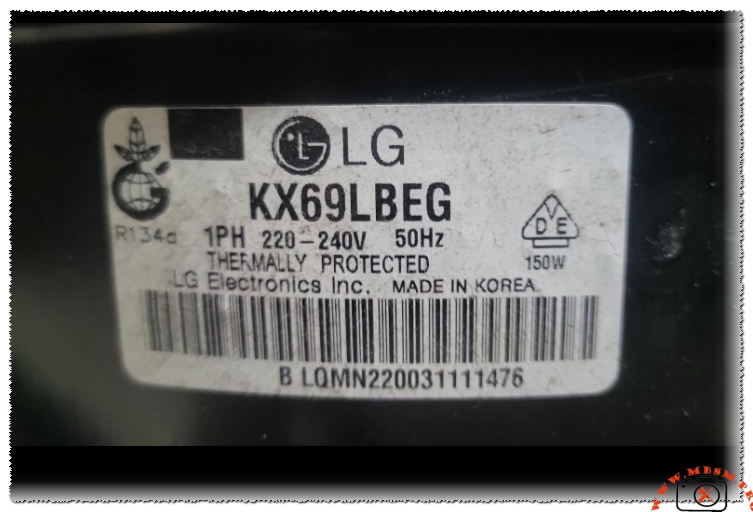
Mastering the LG KX69LBEG: The Heart of Modern Domestic Refrigeration

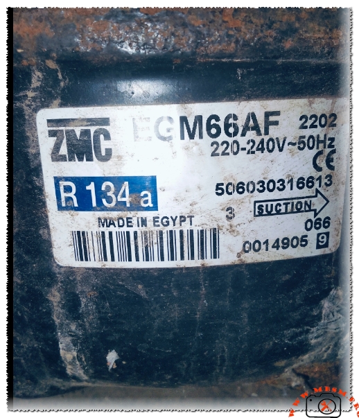
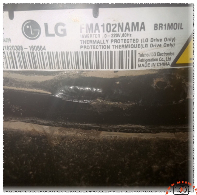
Mbsm.pro, Compressor, KX69LBEG, 1/5 hp, LG Electronics, R134a, 150 W, 1Ph, 220-240V 50Hz, LBP, Reciprocating, -35°C to -10°C, Refrigerator
Technical Specifications Table
| Feature | Details |
| Model | KX69LBEG |
| Utilisation | LBP (Low Back Pressure) |
| Domaine | Freezing / Deep Cooling |
| Oil Type and Quantity | POE or Mineral (R134a compatible) / approx. 180-220ml |
| Horsepower (HP) | 1/5 HP |
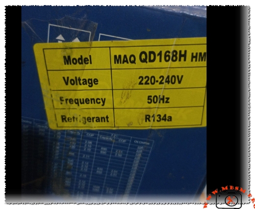
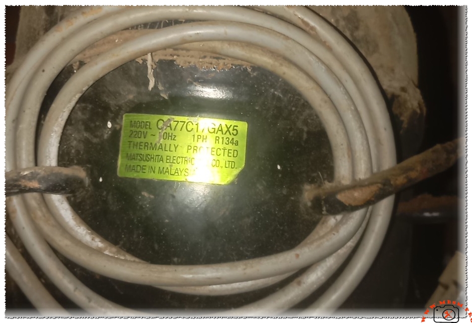
| Refrigerant Type | R134a |
| Power Supply | 220-240V / 50Hz / 1PH |
| Cooling Capacity BTU | Approx. 580 – 620 BTU/h |
| Motor Type | RSIR (Resistance Start – Induction Run) |
| Displacement | 6.9 cm³ |
| Winding Material | Copper |
| Pressure Charge (Suction) | 0.5 to 1.2 Bar (Depending on application) |
| Capillary Recommendation | 0.031″ or 0.036″ (Length varies by cabinet) |
| Refrigerator Models | LG GR-Series, Domestic Single/Double Door units |
| Temperature Function | -35°C to -10°C |
| Fan Requirement | Static Cooling (No fan required for compressor) |
| Commercial Use | No (Domestic / Light Residential) |
| Amperage (RLA) | 0.9A – 1.1A |
| LRA (Locked Rotor Amps) | 5.5A – 6.0A |
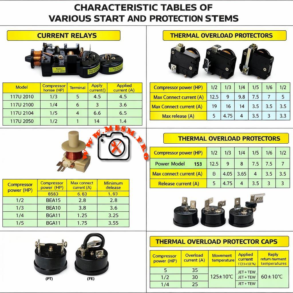
| Type of Relay | PTC Relay |
| Capacitor | Not required (RSIR), optional Start Cap for high torque |
Compressor Cross-Reference (Same Gas – R134a)
- Danfoss/Secop: TLS7F
- Embraco: EMI60HER / NEK1116Z
- Tecumseh: THG1365YS
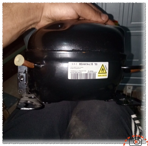
- Samsung: SD162
- ACC/Sikor: GVY66AA
Compressor Cross-Reference (Alternative Gas – R600a)
- LG: MSA69LBEG (R600a version)
- Embraco: EMX55CLC
- Danfoss: TLES5.7KK.3
- Secop: NLE6.0KK
- Jiaxipera: T1112GY
Mastering the LG KX69LBEG: The Heart of Modern Domestic Refrigeration
When a refrigerator fails, the culprit is often the compressor—the mechanical heart that pumps life into the cooling cycle. Among the most reliable workhorses found in household units is the LG KX69LBEG. This 1/5 HP reciprocating compressor is engineered specifically for Low Back Pressure (LBP) applications, making it the ideal candidate for freezers and standard kitchen refrigerators that need to maintain consistent sub-zero temperatures.
Performance Dynamics
The KX69LBEG operates on a displacement of 6.9cc. Unlike larger commercial units that rely on high-torque start capacitors, this model utilizes an RSIR motor configuration. This means it is highly efficient for domestic settings where power stability is standard, drawing approximately 150 Watts during its peak cooling phase. Its thermally protected design ensures that even during high-ambient summer temperatures, the internal windings remain shielded from catastrophic failure.
Comparative Analysis: LG vs. The Competition
In the world of 1/5 HP compressors, the KX69LBEG stands out for its low vibration and silent operation. Compared to the Danfoss TLS7F, the LG model often provides a more compact footprint, which is essential for modern “slim-back” refrigerator designs. While the Embraco NEK1116Z might offer a slightly higher BTU output, the LG KX69LBEG is prized for its longevity and “copper-heavy” winding durability.
Engineering Insights and Installation Tips
- System Cleansing: When replacing a burnt-out KX69LBEG, always flush the condenser and evaporator. Residual acidity from a motor burnout will destroy the new unit.
- Filter Drier: Never reuse a filter drier. Always install a new 15g or 20g XH-9 molecular sieve drier to handle the R134a refrigerant.
- Vacuuming: Ensure a vacuum level of at least 500 microns. R134a is highly sensitive to moisture, which can lead to capillary tube waxing and blockage.
Engineer’s Note: If you are substituting this model with an R600a alternative, you MUST change the expansion device (capillary) and the lubricant. Mixing R134a and R600a systems without proper modification is a recipe for system failure.
Focus Keyphrase: LG KX69LBEG Compressor 1/5 HP R134a Technical Specs
SEO Title: Mbsm.pro – LG KX69LBEG Compressor: 1/5 HP, R134a, LBP Technical Guide
Meta Description: Discover the complete technical specifications for the LG KX69LBEG compressor. This 1/5 HP R134a unit is perfect for domestic refrigerators. Learn about its cooling capacity, amperage, and the best 5 replacements for easy repairs.
Slug: lg-kx69lbeg-compressor-1-5hp-r134a-specifications
Tags: Mbsmgroup, Mbsm.pro, mbsmpro.com, mbsm, LG, KX69LBEG, 1/5 HP, R134a, LBP, Compressor Replacement, TLS7F, EMI60HER, THG1365YS, SD162, GVY66AA, EMX55CLC, TLES5.7KK, Refrigeration Repair.
Excerpt: The LG KX69LBEG is a high-performance 1/5 HP reciprocating compressor designed for Low Back Pressure (LBP) domestic refrigeration. Operating on R134a refrigerant at 220-240V/50Hz, this thermally protected unit is the standard for LG’s cooling reliability. In this guide, we break down its displacement, amperage, and provide a comprehensive list of equivalent replacement models.