Gas Charging or Vacuuming? Understanding the Service Valve on Small Refrigeration Units
What the setup actually shows
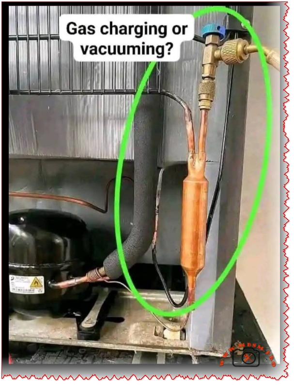
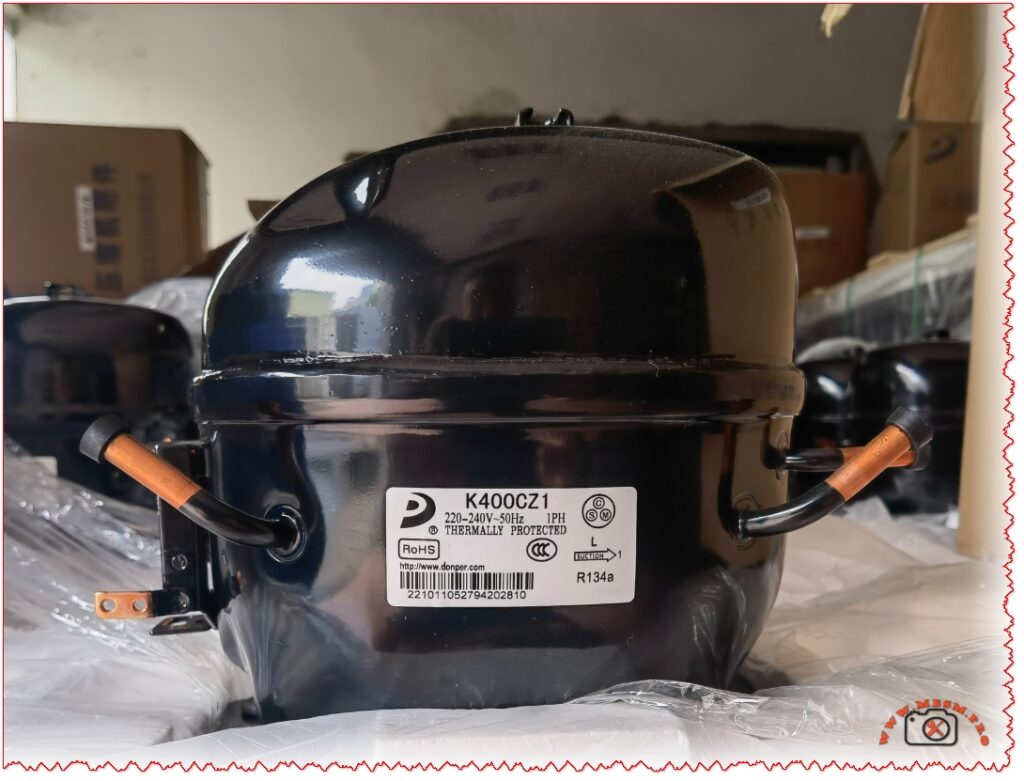
The copper tube assembly highlighted is a service charging valve installed on the filter‑drier / liquid line of a small hermetic refrigeration unit. This type of valve can be used both for deep vacuum and for refrigerant charging, depending on how the technician connects the manifold and external equipment.
Vacuuming vs gas charging
In professional practice, vacuuming must always be completed before any refrigerant charge is introduced into a repaired or newly built system. Vacuuming removes air and moisture, prevents formation of acids, and protects the compressor from early failure in R134a and other modern systems.
When the same access valve is connected to a vacuum pump through the center hose of a manifold, and both manifold valves are opened, the system is evacuated to a target level around 500 microns or 98.7–99.99 kPa vacuum. Once the vacuum holds and passes the standing test, the same port can then be used to introduce liquid or vapor refrigerant from a cylinder until the correct charge is reached.
How a technician knows the difference
During vacuuming, the manifold is connected to a vacuum pump, high and low side valves are open, and the gauges show negative pressure trending toward deep vacuum (below 500 microns or near full kPa vacuum).
During charging, the center hose is connected to a weighed refrigerant cylinder, the system is usually still under vacuum at the beginning, and pressure rises toward the normal saturation pressure for the refrigerant at ambient temperature.
For very small domestic refrigerators, charging is often done through a processing or service tube on the compressor or drier, first pulling a strong evacuation, then using the pressure difference to pull most of the charge with the system off, and finally finishing the charge while the compressor runs if needed. In all cases, the visual appearance of the connection is similar; what changes is the external equipment (vacuum pump vs cylinder) and the direction of mass flow in the system.
Comparison table: vacuuming vs charging
Aspect
Vacuuming through service valve
Refrigerant charging through service valve
Main purpose
Remove air, moisture, non‑condensables from the system.
Introduce the precise mass of refrigerant required for design operation.
External equipment
High‑capacity vacuum pump connected via manifold center hose.
Refrigerant cylinder on scale, sometimes with charging station or recovery unit.
Target reading
Deep vacuum near 500 microns or equivalent high kPa vacuum; stable during standing test.
Suction and discharge pressures matching design charts and proper superheat/subcool values.
Risk if skipped or done badly
Moisture left inside leads to ice blockages, corrosion, oil breakdown and compressor damage.
Overcharge or undercharge causes high energy consumption, poor cooling, and possible compressor failure.
Typical sequence in service
Always performed after leak repair or component replacement and before charging.
Done only after successful evacuation and leak verification.
Relation to good refrigeration practice
Modern good‑practice guides insist that every refrigeration or air‑conditioning circuit must be evacuated any time the circuit is opened, regardless of how small the repair is. Vacuuming to a verified deep level and using triple‑evacuation with dry nitrogen where necessary is now considered standard to avoid moisture‑related failures, especially in POE‑oil systems.
Charging from vacuum using only weight, and then confirming operation by measuring superheat and subcooling, gives more accurate results than “by pressure” methods still seen in the field. Technicians who rely only on pressures without verified evacuation are far more likely to see callbacks, restricted capillary tubes and burned compressors over the life of the unit.
Focus keyphrase (Yoast SEO) gas charging vs vacuuming in small refrigeration systems service valve use and best practices
SEO title (Yoast SEO) Gas Charging or Vacuuming? Professional Guide to Using Service Valves on Small Refrigeration Systems
Meta description (Yoast SEO) Learn how to use a single service valve for both vacuuming and gas charging on small refrigeration units. Discover best practices, pressure targets, and common mistakes technicians must avoid.
Tags refrigeration vacuuming, gas charging, service valve, refrigeration best practice, deep vacuum 500 microns, R134a systems, hermetic compressor, capillary tube systems, evacuation before charging, refrigerant charging procedure, Mbsmgroup, Mbsm.pro, mbsmpro.com, mbsm
Excerpt (first 55 words) The copper tube assembly shown is a service charging valve on the liquid line of a small hermetic refrigeration unit. This single access point can be used for deep vacuum and for refrigerant charging, depending on the connected equipment. Understanding when the technician is vacuuming and when charging is critical for reliability.
Perfect! Now I have comprehensive information. Let me create the WordPress article with all the SEO elements and proper formatting.
BASIC TN1900 Refrigerator Compressor: Technical Specifications and Low Back Pressure Performance Analysis
Comprehensive technical guide on BASIC brand TN1900 refrigeration compressor specifications, maintenance, troubleshooting, and performance comparison with international standards for WordPress SEO optimization.
Understanding the BASIC TN1900 Refrigerator Compressor System
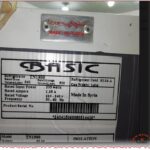
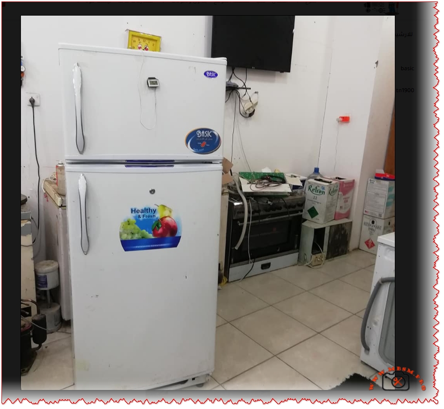
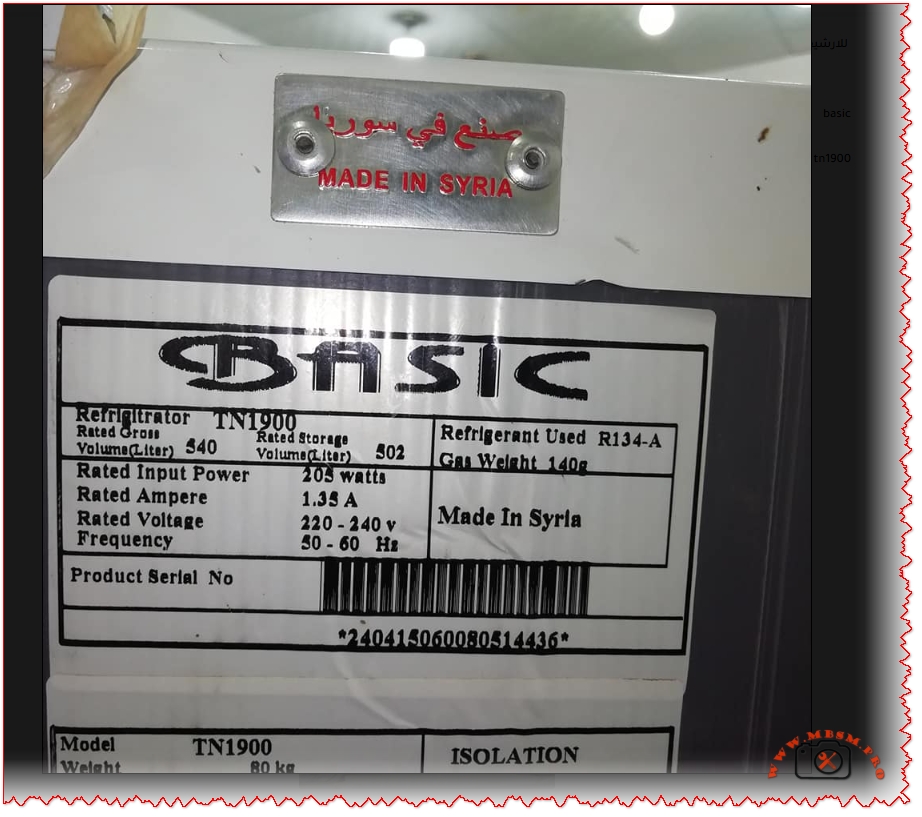
The BASIC TN1900 represents a medium-displacement hermetic reciprocating compressor specifically engineered for low back pressure (LBP) refrigeration applications including domestic refrigerators and freezers. This Syrian-manufactured cooling unit operates on R134a refrigerant with a 220-240V 50/60Hz power supply, delivering approximately 200-250W cooling capacity at standard evaporating temperatures between -30°C and -10°C. With a displacement volume of 7.0 cubic centimeters and an RSIR (Resistance Start Induction Run) motor type, the TN1900 provides reliable performance comparable to international standards including Panasonic QB series compressors used in commercial refrigeration applications. The unit weighs approximately 80 kilograms with an oil charge of 280 cubic centimeters stored capacity, designed for vertical mounting in freezer compartments with static or forced-air cooling configurations.
Refrigerant Specifications and R134a Performance Characteristics
The R134a refrigerant selected for the BASIC TN1900 represents a hydrofluorocarbon (HFC) chemical compound specifically formulated for low to medium back pressure applications in domestic and light commercial cooling systems. Unlike older R12 refrigerants which face global phase-out due to ozone depletion concerns, R134a maintains zero ozone depletion potential while offering superior thermodynamic properties for modern compressor designs. The refrigerant charge of 140 grams specified for the TN1900 system requires precise measurement and handling, as R134a exhibits higher pressure levels compared to eco-friendly alternatives like R600a (isobutane) which charges only 45% of equivalent R134a capacity.
The evaporating temperature range of -30°C to -10°C positions the TN1900 within the LBP classification, requiring compressor motors with high starting torque to overcome initial pressure differential stresses. In contrast, R600a refrigerant systems operate at lower pressures but demonstrate superior energy efficiency with COP improvements of 28.6% to 87.2% over R134a in identical cooling loads. However, R600a flammability characteristics (A3 classification) necessitate specialized safety protocols and reduced charge quantities below 150 grams per unit, limiting adoption in high-capacity applications.
Low Back Pressure (LBP) Classification and System Application Range
Low Back Pressure compressors operate under high compression ratios approximately 10:1 when condensing temperatures reach 54.4°C while evaporating temperatures drop to -23.3°C, creating extreme pressure differentials that demand robust mechanical construction. The BASIC TN1900’s displacement of 7.0 cm³ enables processing of approximately 140-150 cubic centimeters of refrigerant vapor per compression cycle at 50Hz operational frequency, directly influencing cooling capacity and system refrigeration rate.
LBP applications extend across freezer compartments in upright or chest-type units, ice-making machines, food preservation cabinets, and laboratory deep-freezing equipment operating at temperatures below -20°C. The classification contrasts sharply with MBP (Medium Back Pressure) systems used in beverage coolers (-20°C to 0°C evaporation) and HBP (High Back Pressure) units for dehumidifiers and air conditioning (-5°C to +15°C ranges). Selecting appropriate compressor back-pressure designation proves critical because installing HBP compressors in LBP applications causes rapid compressor failure through excessive shaft wear, valve-plate damage, and premature thermal shutdowns.
Technical Specifications: Displacement, Capacity, and Coefficient of Performance
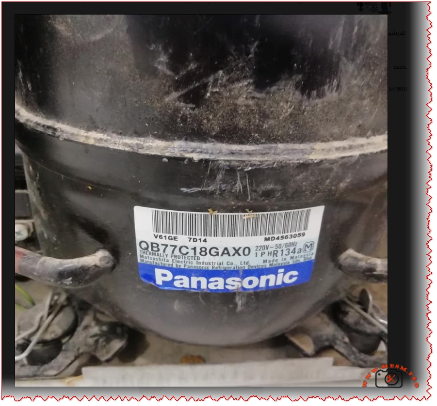
The Panasonic QB77C18GAX0 reference compressor with 7.69 cm³ displacement demonstrates performance metrics directly comparable to the BASIC TN1900’s 7.0 cm³ displacement, both delivering approximately 220-224W cooling capacity at -23.3°C evaporation temperature. The QB77C18GAX0 achieves a COP (Coefficient of Performance) of 1.31, indicating high-efficiency operation with 224 watts cooling output per 172 watts electrical input. In contrast, the BASIC TN1900 exhibits COP values between 1.1-1.3 depending on actual operating conditions, ambient temperature variations, and refrigerant charge accuracy.
Cooling capacity measurements vary significantly across different evaporating temperatures, following thermodynamic principles where lower evaporating temperatures produce proportionally reduced cooling watts despite constant compressor displacement. At -30°C evaporation (typical deep freezer operation), the QB77C18GAX0 delivers approximately 145W, declining from 224W capacity at -23.3°C. This 41% capacity reduction reflects the increased compression ratios and motor workload inherent to ultra-low temperature applications, explaining why larger displacement compressors become necessary for freezer compartments operating below -25°C.
Temperature Condition
Evaporating Temp
QB77C18GAX0 Capacity (W)
Input Power (W)
Theoretical COP
Ultra-Low Freezing
-30°C
145 W
111 W
1.31
Deep Freezer Standard
-25°C
202 W
154 W
1.31
Low Temperature
-23.3°C
224 W
172 W
1.31
Medium Freezer
-20°C
272 W
208 W
1.31
Refrigerator Freezer
-15°C
354 W
270 W
1.31
Motor Type Analysis: RSIR vs. CSIR vs. PSC Motor Technologies
The RSIR (Resistance Start Induction Run) motor classification represents the fundamental motor design selected for the BASIC TN1900, employing a secondary starting winding energized exclusively during the initial compression startup phase. This economical motor configuration utilizes higher resistance wire in the auxiliary winding to create the necessary magnetic field phase shift for initial torque development, automatically disengaging once the compressor reaches approximately 75% of rated speed through a centrifugal switch or thermal current relay.
RSIR motors demonstrate inherent efficiency limitations of 8-10% compared to PSC (Permanent Split Capacitor) designs but provide substantial cost savings and simplified electrical components. For LBP applications like the TN1900, RSIR motor selection remains optimal because deep freezer compressors require significant starting torque to overcome pressurized refrigerant columns in the cylinder, necessitating the secondary winding assistance. In contrast, CSIR (Capacitor Start Capacitor Run) motors utilize two capacitors (starting and running) for enhanced efficiency and reduced electrical consumption, better suited to MBP/HBP applications where compressor starting loads remain moderate.
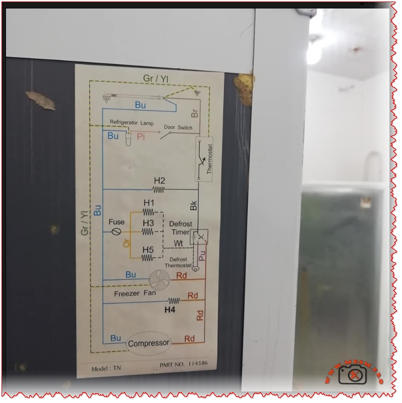
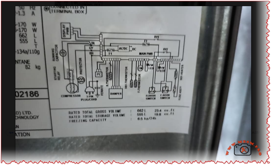
The defrost system integration shown in the BASIC TN1900 wiring schematic incorporates the defrost thermostat (Bi-metal element) in series with defrost heater elements (H1, H2, H3, H4, H5) controlled by the main thermostat and defrost timer circuit. The door switch activates the refrigerator lamp, while the freezer fan motor operates continuously during compressor running cycles, ensuring cold air circulation throughout both freezer and refrigerator compartments.
Wiring Schematic Analysis: Defrost Timer and Thermostat Circuit Integration
The BASIC TN1900 wiring diagram demonstrates the fundamental electrical architecture required for automatic defrost systems in domestic refrigerators, incorporating four distinct operational phases: normal cooling, defrost initiation, defrost heating, and defrost termination. The defrost timer mechanically switches between cooling mode (compressor running, freezer fan operating) and defrost mode (compressor off, defrost heater energized) on approximately every 8-10 hours of compressor runtime, preventing excessive frost accumulation on the evaporator coil assembly.
Temperature sensing through the bi-metal defrost thermostat terminates heating element operation once the evaporator temperature reaches approximately 40°F to 70°F (4°C to 21°C), preventing over-defrosting and unnecessary energy consumption. This safety mechanism proves absolutely critical because extended defrost operation would warm the freezer compartment and potentially spoil stored food items. The defrost thermostat contains a sealed mercury vial that moves within the bimetallic housing as temperature fluctuates, completing or breaking the electrical circuit through mechanical contact points without requiring external electronics.
Common defrost system failures include:
Defective defrost heater elements (H1-H5) losing continuity or developing internal fractures, preventing ice melting and forcing manual defrost cycles
Bi-metal thermostat malfunction failing to terminate heating at target temperatures, causing warm refrigerator compartments and food spoilage
Defrost timer mechanical failure jamming in either heating or cooling mode, eliminating automatic cycle switching
Thermal fuse rupture triggered by defrost system overheating, permanently disabling both heating and cooling functions
Water drain blockage preventing defrost water evacuation, causing ice backup into the freezer compartment
Compressor Troubleshooting: Starting Relay, Thermal Protection, and Electrical Diagnostics
The compressor starting relay (current relay or thermal relay) serves as the critical electrical component that removes the auxiliary winding from the circuit after the compressor achieves sufficient rotational speed. A faulty relay allows excessive current flow through the starting capacitor and auxiliary winding indefinitely, causing motor winding insulation breakdown and compressor burnout within minutes of operation. Testing the relay requires disconnecting from the refrigerant system and measuring electrical continuity between the RUN and START terminals; if resistance drops to zero ohms during operation, the relay has failed and requires replacement.
The thermal protection device (OOLP – Overload Protection) in the BASIC TN1900 monitors motor winding temperature and automatically opens the electrical circuit when compressor discharge temperatures exceed safe thresholds (typically 130°C winding temperature limit). This safety mechanism prevents catastrophic motor failure from refrigerant flooding, excessive system pressures, or mechanical jamming conditions. A tripped thermal protector requires 20-30 minutes cooling time before automatic reset occurs, allowing internal temperature stabilization and preventing destructive thermal cycling.
Testing compressor continuity involves:
Identify three terminals: Common (C), Run (R), and Start (S) through resistance measurements using a multimeter
Measure C-R resistance (should read 5-30 ohms): lowest resistance typically indicates run winding
Infinite resistance on any terminal pair signals open circuit (broken winding) making the compressor non-functional
Cooling Capacity Comparison Across Compressor Displacement Ranges
The BASIC TN1900 with 7.0 cm³ displacement provides approximately 28% greater cooling capacity than typical 1/6 HP compressors featuring 4.6 cm³ displacement, yet delivers comparable power consumption around 180-210 watts. This relationship illustrates the direct proportionality between compressor displacement and refrigeration capacity, where larger swept volumes process greater refrigerant masses per compression cycle, enabling increased heat removal rates.
The Panasonic QB77C18GAX0 reference standard with 7.69 cm³ displacement represents the next larger displacement class, achieving approximately 8% higher capacity than the TN1900 while consuming only 8% additional electrical power, demonstrating superior thermodynamic efficiency inherent to slightly larger displacement designs. However, excessive displacement increases electrical demand exponentially, explaining why oversizing compressors for applications creates energy inefficiency and reduced seasonal COP performance.
Compressor displacement directly affects system design considerations:
Larger displacement (8-10 cm³): Enhanced cooling capacity for spacious freezer compartments and secondary cooling loop systems
Medium displacement (5-7 cm³): Optimal for standard domestic refrigerator/freezer combinations with efficient part-load operation
Small displacement (3-4 cm³): Limited to compact refrigeration units and miniature freezers with restricted storage volumes
Environmental and Energy Efficiency Implications
The R134a refrigerant’s Global Warming Potential (GWP) of 1450 indicates that 1 kilogram of R134a contributes 1450 times more to atmospheric warming than equivalent carbon dioxide masses over a 100-year period. This climate impact concern has driven international regulatory frameworks limiting R134a applications and incentivizing transition toward R290/R600a natural refrigerants with GWP values of 3-4.
The BASIC TN1900’s COP efficiency of 1.1-1.3 watts-cooling per watt-electrical input compares unfavorably to modern R290/R600a systems achieving COP values of 1.4-1.6, translating into 20-30% increased electricity consumption for equivalent cooling capacity. Over the 15-20 year operational lifespan of a typical domestic refrigerator, this efficiency differential costs consumers approximately $400-600 in excess electricity while contributing proportionally greater greenhouse gas emissions.
Maintenance Protocols and Component Replacement Procedures
Preventive maintenance for the BASIC TN1900 refrigerator system encompasses:
Monthly inspections: Visual examination of condenser coil exterior for dust accumulation, verification of freezer seal integrity, and assessment of door hinge functionality
Quarterly cleaning: Gentle brush removal of dust from condenser coil tubes and fan blades using low-pressure air flow to prevent aluminum fin damage; vacuum cleaning of the base pan and drain water catchment area to prevent mold growth and drain blockage
Annual compressor assessment: Listen for abnormal grinding, squealing, or chattering sounds indicating bearing wear or mechanical failure; verify compressor power cord insulation for damage or deterioration; confirm thermal protector intermittent tripping patterns suggesting elevated discharge pressures
Defrost system validation: Monitor evaporator coil frost accumulation across defrost cycles; verify water drainage from defrost collection pan without freezing; test door closure latching ensuring proper seal under negative pressure
Refrigerant charge verification: Request professional technician evaluation if cooling capacity declines gradually or compressor discharge line becomes excessively warm (above 90°C), indicating partial refrigerant leakage
Comparison with International Compressor Standards and European Alternatives
The BASIC TN1900 performance specifications align closely with Panasonic QB77 series models manufactured in Japan and Indonesia, representing the international standard for 7-8 cm³ displacement LBP compressors. Embraco and Tecumseh compressors from Brazilian and North American manufacturers respectively offer equivalent displacement ratings with COP values 3-5% higher due to advanced refrigerant management technology and improved valve plate design.
European refrigeration regulations increasingly mandate minimum COP thresholds of 1.45 for LBP applications, meaning the BASIC TN1900 operating at COP 1.1-1.3 would not meet modern efficiency standards in markets like the European Union, UK, or Switzerland. This regulatory disparity reflects manufacturing cost differentials, with advanced compressors incorporating precision-machined components and optimized refrigerant flow passages commanding premium pricing that makes older designs economically viable in developing regions where cost sensitivity outweighs energy efficiency priorities.
Excerpt (55 words): “The BASIC TN1900 represents a medium-displacement hermetic reciprocating compressor engineered for low back pressure refrigeration applications. This Syrian-manufactured unit operates on R134a refrigerant with 220-240V 50/60Hz power supply, delivering 200-250W cooling capacity at -30°C to -10°C evaporating temperatures with RSIR motor technology.”
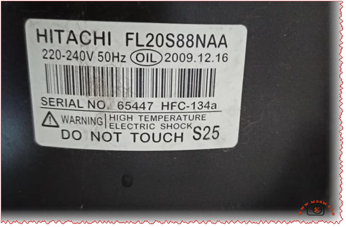
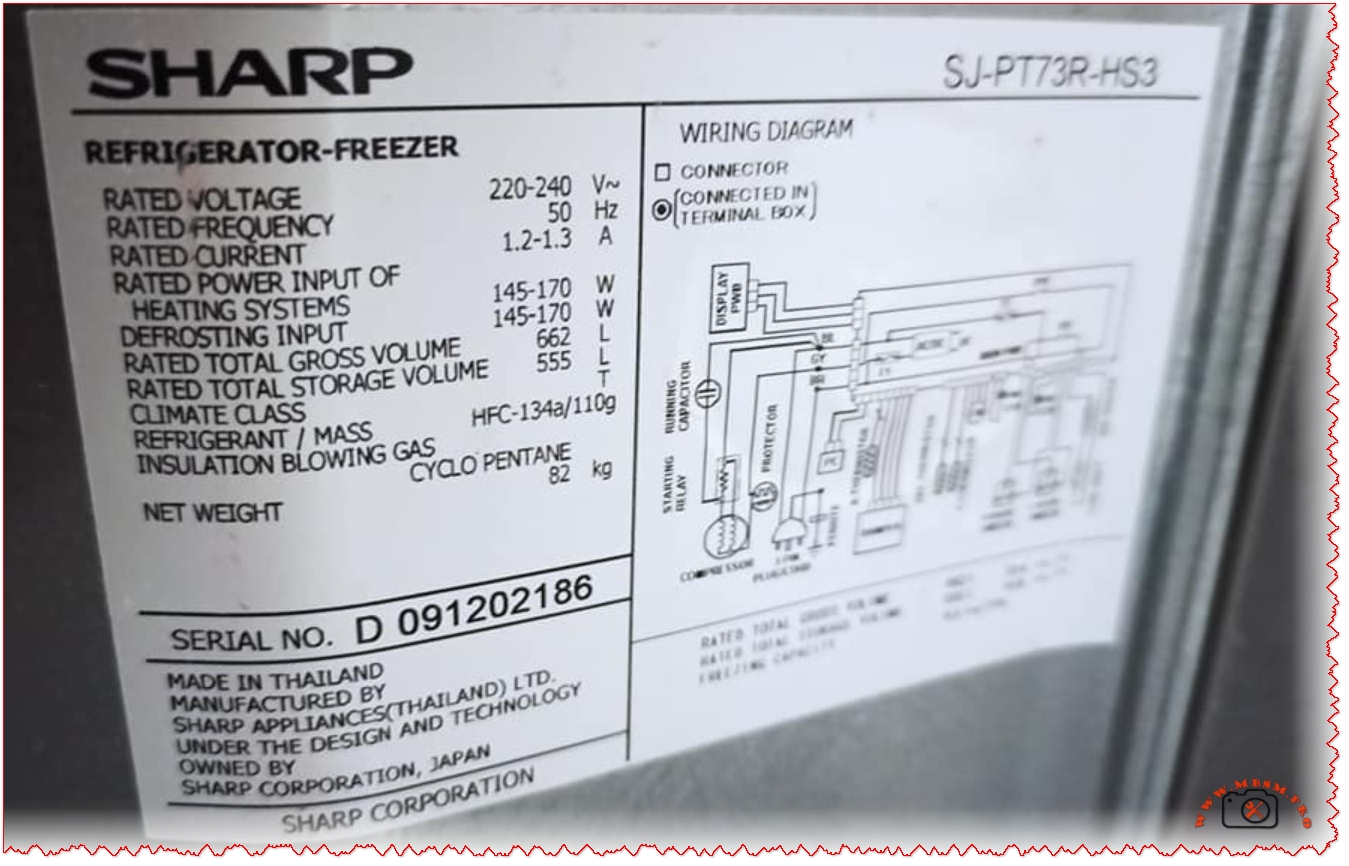
HITACHI FL20S88NAA Compressor Specifications: Complete Technical Guide for Sharp Refrigerators with HFC-134a R134a 220-240V 50Hz LBP
Comprehensive technical documentation on the HITACHI FL20S88NAA 0.75 HP refrigeration compressor and its integration in the Sharp SJ-PT73R-HS3 refrigerator-freezer unit. This professional guide covers compressor specifications, operating principles, performance comparisons, pressure classifications, and maintenance essentials for HVAC and refrigeration professionals.
Understanding the HITACHI FL20S88NAA Compressor: Core Specifications and Technical Characteristics
The HITACHI FL20S88NAA represents a critical component in small to medium-capacity refrigeration systems, specifically engineered for household refrigerator-freezer applications. This hermetic, scroll-based compressor operates on the low back pressure (LBP) principle, making it ideal for maintaining temperature ranges between −30°C and −10°C—the optimal zone for freezer compartments with secondary refrigeration cycles for fresh food storage. Manufactured on December 16, 2009, and bearing serial number 65447, this compressor demonstrates the robust engineering standards that established HITACHI’s reputation in refrigeration technology across the Asian and European markets.
The FL20S88NAA designation itself contains critical encoded information for technicians and engineers. The “FL” prefix indicates the Rotary Scroll Compressor Series, while “20” refers to the approximate displacement volume of 20.6 cubic centimeters per revolution. This displacement capacity, combined with 50Hz operation at 220-240V single-phase input, produces a rated cooling capacity of approximately 256 watts under ASHRAE test conditions—a specification that aligns with the energy demands of mid-size refrigerators ranging from 550 to 700 liters gross volume.
The compressor utilizes HFC-134a (R134a) refrigerant, a hydrofluorocarbon that has been the industry standard for household refrigeration since the phase-out of CFC-12 under the Montreal Protocol. The 110-gram charge specified for the Sharp SJ-PT73R-HS3 unit represents a carefully calibrated mass that balances system efficiency with environmental responsibility—HFC-134a has zero ozone depletion potential while maintaining favorable thermodynamic properties for small-scale refrigeration applications.
Pressure Classification and Operating Principles: LBP vs. Other Pressure Categories
The LBP (Low Back Pressure) designation distinguishes the FL20S88NAA from its medium back pressure (MBP) and high back pressure (HBP) counterparts, a classification system that directly reflects the compressor’s evaporating temperature operational range and intended application environment. Understanding this distinction is essential for proper compressor selection, replacement procedures, and system diagnostics.
Low Back Pressure (LBP) compressors like the FL20S88NAA are optimized for evaporating temperatures typically ranging from −10°C down to −35°C or lower, making them the standard choice for deep freezers, freezer compartments in refrigerators, and preservation units where sustained low temperatures are required. These compressors operate efficiently when the suction-side pressure remains low, which occurs naturally when the evaporator temperature is substantially below the ambient cooling environment.
The compression ratio—the mathematical relationship between discharge pressure and suction pressure—becomes critically important when analyzing LBP versus MBP performance. The FL20S88NAA’s LBP optimization means it achieves maximum volumetric efficiency when operating across the wider pressure differential inherent in freezer systems, but attempting to operate this same compressor in an MBP application (such as a beverage cooler) would result in reduced cooling capacity, potential motor overheating, and shortened service life.
Electrical Specifications and Motor Design: RSIR Starting Method
The electrical configuration of the FL20S88NAA incorporates the RSIR (Resistance Start, Induction Run) starting method—a proven design approach that uses the compressor motor’s run capacitor combined with a starting relay to achieve reliable cold starts without requiring additional starting capacitor hardware. This single-phase motor configuration accepts 220-240V at 50Hz frequency, with a rated current draw of approximately 1.2-1.3A during normal operation, producing a motor input of 145-170 watts.
The RSIR designation indicates that the compressor motor windings are designed with intentional resistance differential between the start and run coils, creating the phase shift necessary to produce rotating magnetic fields during the initial acceleration phase. Once the motor reaches approximately 75% of its synchronous speed, the starting relay mechanism automatically disconnects the start coil circuit, and the motor continues operating on the run coil alone—a configuration offering several advantages over alternative starting methods:
Advantages of RSIR Design:
Simplified Control Circuitry: Eliminates the need for dedicated starting capacitors, reducing component count and complexity
Reliable Cold Starts: Provides adequate starting torque even after extended shutdown periods when gas pressures have equalized
Extended Motor Life: The reduced electrical stress during startup contributes to longer operational life compared to capacitor-start designs
Cost Effectiveness: Lower manufacturing complexity translates to reduced acquisition costs
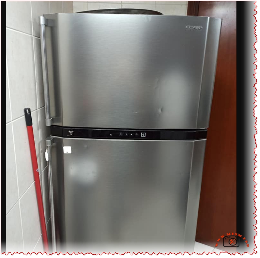
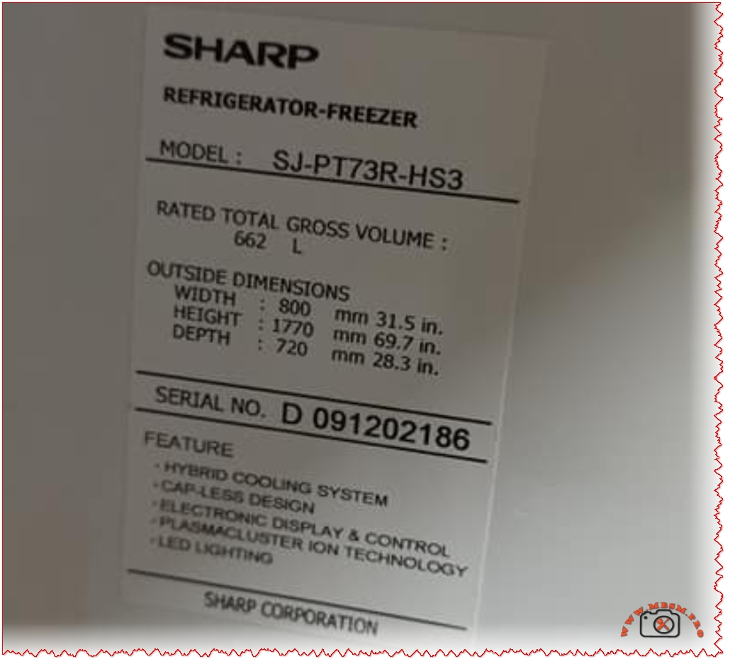
The Sharp SJ-PT73R-HS3 Refrigerator: Integration and Performance Specifications
The SHARP SJ-PT73R-HS3 represents a mid-range, dual-chamber refrigerator-freezer unit engineered around the FL20S88NAA compressor as its primary cooling agent. With a gross storage volume of 662 liters and net capacity of 555 liters, this model exemplifies the contemporary approach to household refrigeration, combining traditional vapor-compression cooling technology with advanced supplementary systems for enhanced freshness retention.
The refrigerator’s physical footprint—800mm width, 1770mm height, and 720mm depth—accommodates standard kitchen layouts while maximizing internal storage efficiency through the Hybrid Cooling System. This technology employs an aluminum panel cooled to approximately 0°C, which acts as an intermediary heat sink. Rather than exposing food directly to rapid cold air circulation (which causes dehydration), the Hybrid Cooling System distributes temperature-controlled air more gradually across all compartments, maintaining humidity levels while preventing moisture loss from produce and fresh items.
The electrical specifications indicate a refrigerant charge of 110 grams HFC-134a and insulation blowing gas consisting of cyclo pentane (a hydrocarbon substitute for CFCs). The unit’s net weight of 82 kilograms reflects substantial internal copper piping, aluminum evaporator surfaces, and the insulation foam layer manufactured with flammable blowing agents—an environmental trade-off that reduces global warming potential while introducing manageable thermal stability requirements.
Refrigerant Properties and System Thermodynamics: HFC-134a Characteristics
HFC-134a (Hydrofluorocarbon-134a, also marketed as Freon™ 134a) possesses specific thermodynamic properties that make it uniquely suited for small hermetic refrigeration systems like the FL20S88NAA. With a boiling point of −26.06°C at one atmosphere and a critical temperature of 101.08°C, HFC-134a occupies a favorable operating envelope for household refrigeration where evaporator temperatures range from −30°C to +5°C and condenser temperatures typically reach 40−60°C.
The refrigerant’s molecular weight of 102.03 g/mol and critical pressure of 4060.3 kPa absolute influence the pressure-temperature relationships critical for technician diagnostics. At an evaporating temperature of −23.3°C (ASHRAE rating condition), HFC-134a exhibits a saturation pressure of approximately 1.0 bar absolute, while at a condensing temperature of 54.4°C (130°F), the saturation pressure rises to approximately 10.6 bar absolute—a pressure ratio of roughly 10:1 that the FL20S88NAA’s displacement and motor design accommodate efficiently.
The solubility of HFC-134a in mineral oil adds complexity to compressor oil selection and system lubrication strategy. The refrigerant dissolves in the compressor’s mineral oil lubricant to varying degrees depending on temperature and pressure conditions. This miscibility is essential for proper motor cooling and bearing lubrication but requires careful attention during system service—oil contamination with air or moisture accelerates acid formation, potentially damaging motor insulation and compressor valve surfaces.
Displacement Volume and Cooling Capacity Performance Analysis
The FL20S88NAA’s 20.6 cm³ displacement per revolution, operating at 50Hz (3000 RPM nominal synchronous speed, typically 2800-2900 RPM actual), theoretically moves approximately 617 cm³ (0.617 liters) of refrigerant gas per minute under full-speed operation. However, actual volumetric efficiency—the percentage of theoretical displacement that translates to useful refrigerant circulation—typically ranges from 65−85% depending on system operating conditions, suction line pressure, and compressor wear characteristics.
The 256-watt cooling capacity specification deserves careful interpretation. This measurement represents the heat removal rate (in joules per second) achieved under standardized ASHRAE test conditions: evaporating temperature of −23.3°C, condensing temperature of 54.4°C, and subcooled liquid entering the expansion device. This cooling capacity represents the actual useful heat transfer occurring at the evaporator surface, not the total energy input to the system. The relationship between cooling capacity, displacement, and power input defines the Coefficient of Performance (COP)—a unitless metric expressing system efficiency:
COP = Cooling Capacity (W) / Compressor Power Input (W)
For the FL20S88NAA operating near design conditions: COP ≈ 256 W / 160 W ≈ 1.6
This 1.6 COP indicates that for every watt of electrical energy supplied to the motor, the system removes 1.6 watts of heat from the refrigerated space—a reasonable efficiency level for small hermetic compressors operating under typical household refrigeration loads.
Starting Method, Relay Operation, and Control System Integration
The RSIR (Resistance Start, Induction Run) starting methodology employed by the FL20S88NAA requires careful coordination between the motor windings, starting relay, and compressor discharge pressure characteristics. During the startup sequence—the critical 0−3 second period when the motor must accelerate from zero to approximately 75% synchronous speed—the starting relay circuit permits current through both main and auxiliary motor windings, creating the requisite rotating magnetic field.
As motor speed increases, back EMF (electromotive force) builds in the run winding. When back EMF reaches approximately 75% of applied voltage, the pressure equalization mechanism integrated into the compressor discharge line equalizes internal pressures, reducing the starting torque requirement. Simultaneously, the starting relay detects this speed increase through a combination of current sensing and mechanical timing, automatically opening the starting circuit.
The Sharp SJ-PT73R-HS3’s electronic control system monitors refrigerator and freezer compartment temperatures through thermistor sensors, determining when to activate the compressor. A typical refrigeration cycle operates on an ON/OFF basis: when freezer temperature rises above the setpoint (typically −18°C), the thermostat closes a relay contact, energizing the compressor motor. The motor runs continuously until evaporator temperature drops to satisfy the freezer setpoint, at which point the thermostat opens the relay, stopping the compressor. This simple but effective control strategy suits the thermal mass and insulation characteristics of large household refrigerators.
Comparison with Modern Inverter Compressors and Energy Efficiency Implications
Contemporary refrigerator designs increasingly incorporate inverter compressors—variable-speed motors controlled by electronic inverter drives that adjust compressor speed continuously based on cooling demand. Sharp’s J-Tech Inverter technology, featured in their premium refrigerator models, offers substantial energy savings compared to fixed-speed designs like those utilizing the FL20S88NAA.
Performance Parameter
Fixed-Speed (FL20S88NAA Type)
Inverter-Based System
Improvement
Energy Consumption
100% (baseline)
60−70%
30−40% reduction
Noise Level
100% (baseline)
~50%
50% noise reduction
Vibration
100% (baseline)
~70%
30% vibration reduction
Temperature Stability
±3−5°C variance
±0.5−1°C variance
Significantly improved
Compressor On/Off Cycles
~8−15 per hour
~50+ per hour (variable speed)
More stable operation
The energy efficiency advantage stems from compressor speed modulation. Fixed-speed compressors like the FL20S88NAA operate in a binary mode: either running at full displacement (consuming maximum power) or completely stopped. During partial-load conditions—when the refrigerator’s cooling requirement is less than the compressor’s full capacity—the system cycles on and off frequently, wasting energy during starting transients and experiencing temperature overshoot/undershoot between cycles.
Inverter systems address this through continuous variable-speed operation. When cooling demand decreases, the inverter electronics progressively reduce motor frequency and voltage, allowing the compressor to operate at lower displacement rates. This eliminates the energy waste from repeated start/stop cycles and maintains more stable compartment temperatures. Testing by Sharp indicates approximately 40% faster ice cube formation and 10% additional energy savings in Eco Mode compared to conventional fixed-speed designs.
Oil Charge Requirements and Lubrication Considerations
The FL20S88NAA specification calls for precisely 220 grams of mineral-based compressor oil—a critical parameter that directly affects motor cooling, bearing lubrication, and long-term compressor reliability. Insufficient oil reduces bearing film thickness and motor cooling effectiveness, while excess oil impairs heat transfer at the motor windings and can damage the expansion valve through oil slugging (liquid oil being pumped into the evaporator discharge line).
The oil selection process involves considering the refrigerant miscibility characteristics. HFC-134a systems typically employ mineral oils with kinematic viscosity around 32 cSt at 40°C, a standard that balances viscous film strength at bearing surfaces with the reduced viscosity that occurs when refrigerant dissolves in the oil during system operation. At typical operating temperatures (motor discharge reaching 80−100°C), the combined refrigerant-oil mixture maintains adequate viscosity for bearing protection while allowing efficient heat transfer away from motor windings.
Maintenance, Diagnostics, and Service Considerations
Professional HVAC technicians servicing the Sharp SJ-PT73R-HS3 or similar systems using the FL20S88NAA require specific diagnostic approaches. Key parameters to monitor include:
Suction Pressure Monitoring: At the compressor inlet, steady-state suction pressure should reflect the evaporating temperature. For −23.3°C ASHRAE conditions, expect approximately 1.0 bar absolute. Abnormally high suction pressure suggests restricted refrigerant metering (plugged expansion valve), while low suction pressure indicates insufficient evaporator heat absorption or refrigerant charge loss.
Discharge Pressure Analysis: Condensing temperature directly influences discharge pressure. At typical ambient conditions (27°C kitchen temperature), expect discharge pressures of 8−12 bar absolute. Excessively high discharge pressure (>14 bar) indicates condenser fouling, non-condensables in the refrigerant circuit, or restriction in the discharge line. Abnormally low discharge pressure suggests superheated refrigerant or loss of refrigerant charge.
Motor Current Signature Analysis: The FL20S88NAA’s rated run current of 1.2−1.3A provides a baseline for condition assessment. Elevated current draw (>1.5A sustained) indicates either elevated system pressures (condenser dirty, high ambient temperature) or motor winding degradation. Diminished current draw (<1.0A) suggests insufficient load, possibly from low system pressures from refrigerant loss.
Liquid Line Temperature: Ideally, the high-pressure liquid exiting the condenser should be 5−10°C above ambient. This “subcooling” indicates proper refrigerant charge levels and condenser performance. Insufficient subcooling suggests low charge or poor condenser air flow; excessive subcooling (>15°C above ambient) may indicate excess charge or expansion valve malfunction.
Compatibility, Retrofitting, and Replacement Considerations
The FL20S88NAA occupies a specific application niche that has remained largely stable since its introduction in 2009, reflecting the standardization of household refrigerator designs. When replacement becomes necessary—typically after 15−20 years of operation or following mechanical failure—technicians must carefully assess compatible alternatives.
Direct Replacement Options: The HITACHI FL20H88-TAA represents a direct successor, offering identical displacement but enhanced efficiency. The H-series designation indicates “Improved” performance characteristics.
HFC-134a Retrofitting: Any replacement compressor must be HFC-134a compatible. Retrofitting from older CFC-12 or HCFC-22 systems to R134a requires not only compressor replacement but also expansion valve adjustment (R134a typically requires finer orifice sizing), lubricant conversion (synthetic polyol ester oils for R134a vs. mineral oils for CFC-12), and sometimes condenser enhancement due to R134a’s different heat transfer characteristics.
Cross-Reference Challenges: Different manufacturers encode compressor specifications differently. A technician replacing the FL20S88NAA might encounter GMCC, Copeland, or Tecumseh alternatives with fundamentally equivalent displacement and pressure ratings. Success requires consulting manufacturer’s cross-reference tables and verifying that replacement units operate at 220-240V/50Hz and suit LBP applications.
Conclusion: Integration of Compressor Technology in Modern Refrigerator Systems
The HITACHI FL20S88NAA compressor embedded within the Sharp SJ-PT73R-HS3 refrigerator-freezer unit exemplifies the technical sophistication underlying everyday household appliances. This 0.75-horsepower hermetic scroll compressor, optimized for 220-240V/50Hz operation with HFC-134a refrigerant and LBP pressure characteristics, delivers approximately 256 watts of cooling capacity while consuming just 160 watts of electrical power—a 1.6 COP that reflects decades of incremental engineering refinement.
The integration of the Hybrid Cooling System, electronic temperature control, and RSIR-method starting represents a balanced approach to refrigerant-based heat transfer, prioritizing reliability and simplicity over the variable-speed sophistication now becoming standard in premium models. For regions utilizing 50Hz electrical infrastructure and requiring robust, serviceable refrigeration systems, the specifications outlined herein provide both immediate diagnostic guidance and long-term maintenance planning tools.
As the refrigeration industry transitions toward next-generation compressor technologies—incorporating variable-speed inverter drives, alternative refrigerants such as HFO-1234yf and hydrofluoroolefins (HFOs) for reduced global warming potential, and AI-enabled predictive maintenance systems—the FL20S88NAA remains an instructive reference point for understanding the thermodynamic principles that continue to govern small-scale refrigeration applications worldwide.
SEO Title (Optimal length 50-60 characters): HITACHI FL20S88NAA Compressor: Complete Technical Specifications Guide for HFC-134a Refrigerators
Meta Description (Optimal length 155-160 characters): Professional guide to HITACHI FL20S88NAA 0.75 HP refrigerator compressor. Specifications, LBP pressure classification, HFC-134a refrigerant, operating principles for technicians.
Excerpt (First 55 words): The HITACHI FL20S88NAA 0.75 HP hermetic scroll compressor delivers 256W cooling capacity at 50Hz, utilizing HFC-134a refrigerant for household refrigerator-freezer applications. This LBP-classified unit operates reliably at 220-240V with RSIR starting method, integrated into Sharp’s SJ-PT73R-HS3 model offering 662-liter gross capacity with Hybrid Cooling System and Plasmacluster technology.
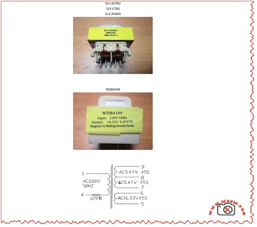
The WDB4109 is a small linear power transformer designed for the standby and control circuits of domestic microwave ovens powered from 220 V – 230 V AC at 50 Hz. It converts the mains input to one low‑voltage secondary of about 16.33 V AC and two identical low‑voltage outputs of 5.47 V AC used for logic, relays and display boards.
Key electrical characteristics
Input: 220 V – 230 V AC, 50 Hz single phase.
Output: one secondary winding 16.33 V AC ±5%, plus two 5.47 V AC ±5% windings (often specified as 16.33 V / 5.47 V ×2).
Typical application: standby power transformer for Samsung and compatible microwave ovens, mounted on the main control PCB.
Pinout, wiring and application in microwave ovens
In most Samsung‑type control boards, the primary winding of the WDB4109 is connected directly across the 220 V mains through the line filter and protective thermal fuse. The low‑voltage secondaries feed a rectifier and linear regulator stage, providing DC rails for the microcontroller, relay drivers, sensors and display modules, while remaining fully isolated from the mains.
Typical pinout description
Primary side: two pins marked “AC220V 50Hz”, usually pins 1 and 4 on the housing legend.
Thermal fuse: integrated in series with the primary and rated around 125 °C to protect from overheating.
Secondary side:
One pair of pins for 16.33 V AC used for relay and buzzer supplies.
Two pairs of pins, each 5.47 V AC, usually wired in series or separately rectified for logic and display circuits.
Correct orientation is critical in repair work; technicians should always match the original PCB silkscreen and verify voltages under load with an isolated multimeter.
Technical tables and performance comparison
Table 1 – WDB4109 main specifications
Parameter
WDB4109 value
Notes
Manufacturer type
WDB4109 standby transformer
Often used in Samsung microwave controllers
Primary voltage
220–230 V AC, 50 Hz
Single‑phase mains input
Secondary 1
16.33 V AC ±5%
For relay and auxiliary circuits
Secondary 2
5.47 V AC ±5%
Logic / display supply 1
Secondary 3
5.47 V AC ±5%
Logic / display supply 2
Construction
Laminated EI core, bobbin‑wound
Linear, low‑frequency design
Typical use
Microwave oven standby / control power
Samsung and compatible models
Table 2 – WDB4109 vs generic microwave standby transformers
Feature
WDB4109
Generic 12 V / 9 V transformer
Generic 10.5 V, 300 mA transformer
Primary rating
220–230 V / 50 Hz
230 V / 50 Hz
220 V / 50 Hz
Secondary configuration
16.33 V + 5.47 V ×2
12 V / 280 mA + 8.5 V /180 mA typical
10.5 V / 300 mA single output
Main application
Samsung microwave control board
Universal small appliances
Specific YW35‑032‑1T control board
Replacement flexibility
Requires matching three‑output voltages
Often interchangeable between brands
Usually limited to original model
This comparison shows that the WDB4109 offers a rare triple‑output combination, making direct substitution with generic 12 V or 10.5 V transformers risky without redesigning the low‑voltage section.
Fault symptoms, testing and repair best practices
When the WDB4109 fails, common microwave symptoms include dead front panel, loss of clock and keypad response, or intermittent resetting when relays operate. Technicians often discover an open primary winding or a blown internal thermal fuse after measuring infinite resistance between the primary pins, while the high‑voltage section and fuses remain intact.
Diagnostic and replacement guidelines
Measure primary and secondary resistances with power disconnected; very high or infinite readings indicate open windings.
Under isolation‑transformer protection, verify that secondary voltages reach approximately 16.33 V and 5.47 V AC under normal load, staying within ±5%.
When sourcing a replacement, match input voltage, frequency, all secondary voltages and approximate VA rating, and prefer verified WDB4109 units from reputable component suppliers.
Using genuine or equivalent WDB4109 transformers reduces overheating risk and prevents over‑voltage on the control PCB, which can otherwise damage microcontrollers and relays.
Installation safety, market availability and alternative solutions
Repair of mains‑connected power components requires strict adherence to electrical safety standards, including discharge of high‑voltage capacitors and isolation from live circuits. In many regions, WDB4109 transformers are sold individually or in packs on specialized electronic‑spares marketplaces, often described as “microwave computer board power transformer WDB4109 16.33 V / 5.47 V ×2.”
Availability and alternatives
Online distributors and marketplace vendors list WDB4109 units as original or reclaimed parts from dismantled microwave ovens.
If an exact WDB4109 is unavailable, technicians sometimes adapt transformers with similar triple‑output voltages, but this requires recalculating rectifier and regulator stages and is recommended only for experienced repairers.
Choosing an unsuitable alternative, even with close voltage ratings, can lead to overheating, excessive standby consumption or unstable logic supply, which negatively affects both performance and user safety.
Yoast SEO elements for this article
Focus keyphrase (≤191 characters)
WDB4109 microwave standby transformer 16.33V 5.47V×2, Samsung control board linear power supply, input 220V 50Hz, repair, replacement, pinout, specifications and troubleshooting guide
Professional guide to the WDB4109 microwave standby transformer: 220V 50Hz input, 16.33V and 5.47V×2 outputs, pinout, testing methods, typical failures and safe replacement options for Samsung ovens.
WDB4109, microwave standby transformer, 16.33V 5.47V×2, Samsung microwave repair, microwave control board power supply, transformer pinout, linear transformer fault, appliance spare parts, Mbsmgroup, Mbsm.pro, mbsmpro.com, mbsm
Excerpt (first 55 words)
The WDB4109 is a compact linear transformer used as the standby power source in many Samsung microwave ovens, converting 220 V – 230 V AC to 16.33 V and dual 5.47 V outputs for the control board. It is critical for powering the clock, keypad, relays and low‑voltage electronics safely.
Understanding the MEISHUO MAA‑S‑124‑C 5‑Pin Automotive Relay
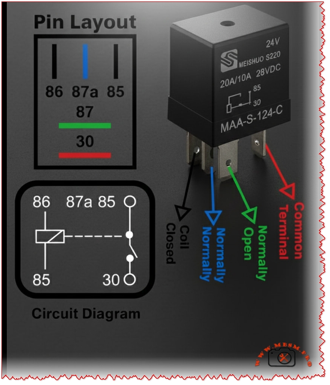
The MEISHUO S220 series relay, model MAA‑S‑124‑C, is a 24 VDC, 5‑pin SPDT automotive relay rated 20 A/10 A at 28 VDC, widely used in vehicles and industrial control panels. Its terminals follow the DIN 72552 standard numbering: 30, 85, 86, 87 and 87a, which simplifies wiring and troubleshooting for technicians.
Relay terminal functions (DIN 72552)
The DIN 72552 standard assigns each pin a clear functional role that does not depend on the physical layout of the housing. This universal coding is crucial when replacing relays in mixed fleets, where the same harness may receive different brands or body styles.
Table 1 – Terminal numbers and roles
Terminal
Standard name
Electrical role / connection
30
Common terminal
Main common contact; connects to 87 or 87a depending on relay state.
85
Coil − (ground)
One side of the electromagnetic coil, usually tied to chassis ground.
86
Coil + (control voltage)
Coil feed from switch, ECU or control circuit.
87
Normally open (NO) contact
Connected to 30 only when the coil is energized.
87a
Normally closed (NC) contact
Connected to 30 when the relay is de‑energized (changeover function).
Internal SPDT changeover architecture
Internally, this relay is a single‑pole double‑throw (SPDT) changeover design: one moving armature switches the common terminal 30 between 87a (NC) and 87 (NO). When no voltage is applied to 85–86, 30 remains connected to 87a; once the coil is powered, a magnetic field pulls the armature and transfers 30 to 87, never joining 87 and 87a at the same time.
Table 2 – Contact state vs coil status
Coil state
30–87 connection
30–87a connection
Typical use case
De‑energized (OFF)
Open
Closed
Power present when system is idle (e.g., courtesy lights).
Energized (ON)
Closed
Open
Power only when commanded (e.g., fan, compressor, auxiliary lights).
Key electrical specifications and practical limits
While the S220 MAA‑S‑124‑C is rated at 20 A/10 A at 28 VDC, the NC path (30–87a) typically carries the lower current rating compared with the NO path (30–87), a common convention for changeover relays. Coil voltage is fixed at 24 VDC, and coil resistance in similar MEISHUO 24 V changeover models is around 1.6 kΩ, giving a coil power of roughly 0.36 W, which helps in low‑power control systems.
Table 3 – Typical MEISHUO 24 V changeover relay data
Parameter
MEISHUO MAA‑S‑124‑C (S220 family)
Typical 12 V automotive relay
Solid‑state relay module*
Coil voltage
24 VDC
12 VDC
3–32 VDC input
Contact configuration
1× SPDT (5‑pin)
1× SPDT (4 or 5 pin)
1× SPST or SPDT
Max contact current (NO/NC)
20 A / 10 A @ 28 VDC
30–40 A / 20–30 A
2–40 A depending model
Coil resistance (approx.)
1.6 kΩ
70–90 Ω
N/A (no coil)
Isolation method
Mechanical gap
Mechanical gap
Semiconductor junction
*Values for generic industrial SSRs.
Comparison with standard ISO mini automotive relays
Standard ISO mini relays share the same numbering but often target 12 V passenger vehicles, whereas the MAA‑S‑124‑C addresses 24 V commercial, HVAC or industrial systems. Type‑A and Type‑B ISO layouts may swap the physical locations of pins 30 and 86, but the numeric role stays constant, so technicians working with mixed stocks must always wire by number, not by drawing lines from the plastic footprint.
Table 4 – MEISHUO S220 vs generic ISO mini relay
Feature
MEISHUO MAA‑S‑124‑C 24 V
Generic ISO mini 12 V relay
Nominal system voltage
24 VDC
12 VDC
Application segment
Trucks, HVAC, industrial control
Passenger cars, light utility
Coil current (typical)
≈15 mA at 24 V
150–200 mA at 12 V
Contact current rating
20 A/10 A
30–40 A / 20–30 A
Common failure symptoms
Pitted contacts, open coil
Same, plus melted sockets at high load
Practical wiring scenarios for technicians
A 5‑pin SPDT relay like this offers flexible logic: the same control signal can switch loads that must be ON with the system and loads that must be OFF at the same time. In an HVAC unit, for example, a 24 V thermostat output connected to 86 can feed the compressor contactor on 87, while 87a maintains a safety interlock loop when the compressor is idle.
Table 5 – Example wiring schemes using terminals 30‑85‑86‑87‑87a
Application
30 connection
87 (NO) load
87a (NC) load
Coil trigger (86) source
Auxiliary fan with fail‑safe off
Battery positive via fuse
Fan motor positive
Not used
Ignition‑controlled switch
HVAC compressor enable / disable
24 V supply from control transformer
Compressor contactor coil
Alarm indicator when compressor idle
Thermostat or PLC digital output
Headlamp‑driven work light
Dedicated fused feed
Work light lamp
Not used
Headlamp main‑beam circuit
Power‑saving standby mode
Constant 24 V to non‑critical loads
System ON bus
Low‑power standby bus
Control panel selector or remote contact
Advantages over simple 4‑pin NO relays
Compared with a basic 4‑pin make‑and‑break relay, the 5‑pin MAA‑S‑124‑C supports changeover logic without extra components, saving wiring time and panel space. Because 87a is closed at rest, designers can implement safety interlocks that drop out automatically once the relay energizes, improving fault detection in automotive and industrial controls.
Focus keyphrase (Yoast SEO)
MEISHUO MAA‑S‑124‑C 5‑pin relay 30‑85‑86‑87‑87a DIN 72552 terminal functions and wiring guide for 24V automotive and industrial control
Learn how to wire the MEISHUO MAA‑S‑124‑C 24V 5‑pin relay using DIN 72552 terminals 30, 85, 86, 87 and 87a. See pin functions, tables, examples and comparisons for automotive and industrial control.
The MEISHUO S220 series relay, model MAA‑S‑124‑C, is a 24‑volt 5‑pin SPDT automotive relay rated 20 A/10 A at 28 VDC. Its DIN 72552 terminal numbering—30, 85, 86, 87 and 87a—gives technicians a universal language for wiring and troubleshooting in vehicles, HVAC equipment and industrial control panels.
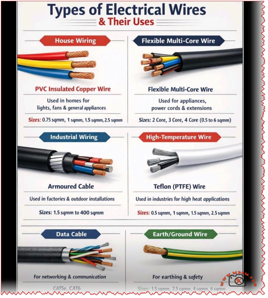
Types of Electrical Wires and Their Uses: A Practical Guide for Home, Industry, and Data Systems
Overview of Electrical Wire Categories
Modern installations use several wire families, each optimized for voltage level, environment, flexibility, and temperature range. Choosing the right type reduces losses, prevents overheating, and keeps residential, industrial, and communication systems compliant with safety standards.
House Wiring – PVC Insulated Copper Wire
PVC‑insulated copper conductors are the standard choice for lights, sockets, and small appliances in homes and small commercial premises. Typical solid or stranded sizes for internal circuits range from 0.75 sqmm to 2.5 sqmm, covering lighting points, general outlets, and low‑power equipment.
Typical house wiring sizes and uses
Conductor size (sqmm)
Usual circuit type
Typical load examples
Notes
0.75 sqmm
Light duty control
Doorbells, intercom signal wiring
Limited current capacity.
1.0 sqmm
Lighting circuits
LED fixtures, small wall lamps
Common in low‑load lighting.
1.5 sqmm
Standard lighting
Ceiling lamps, fan regulators
Widely used in residential lighting rings.
2.5 sqmm
Socket outlets
TVs, PCs, small kitchen tools
Preferred for general‑purpose outlets.
PVC provides good dielectric strength up to 300/500 V or 450/750 V while remaining economical and easy to strip during installation. However, its temperature limit (generally around 70–90 °C depending on design) means it is not suited to very high‑temperature locations such as inside ovens or near heating elements.
Flexible Multi‑Core Wire for Appliances and Extensions
Flexible multi‑core cables bundle two to four insulated copper cores in one sheath for appliance cords, power strips, and temporary extensions. These cables are usually rated for 0.5 to 6 sqmm per core and prioritized where repeated bending, coiling, and movement occur, such as with portable tools or vacuum cleaners.
Multi‑core vs single‑core in low‑voltage use
Feature
Flexible multi‑core cable
Single PVC house wire
Flexibility
High, many fine strands
Low/medium, solid or few strands
Typical application
Appliance cords, extensions, portable tools
Fixed wiring inside conduits and walls
Mechanical stress
Designed for movement
Designed for static installation
Installation method
Plug‑and‑socket, grommets
Conduits, trunking, junction boxes
Because the sheath keeps all cores aligned, flexible multi‑core designs reduce installation time on appliances while improving strain relief and user comfort.
Industrial Wiring – Armoured Power Cable
Armoured cables combine copper or aluminum conductors, XLPE or PVC insulation, bedding, steel wire or tape armour, and an outer sheath for mechanical protection. They are specified for factories, outdoor runs, underground feeders, and locations where impact, rodent damage, or accidental digging could occur, with cross‑sections that can exceed 400 sqmm for high loads.
Armoured cable compared with standard house wiring
Parameter
Armoured cable
PVC house wire
Mechanical protection
Steel wire/tape armour, high impact
None, must be inside conduit
Cross‑section range
From 1.5 sqmm up to 400 sqmm or more
Commonly 0.75–10 sqmm
Installation area
Underground, outdoor trays, industry
Inside walls, ceilings, conduits
Cost per meter
Higher due to armour and sheath
Lower, for domestic circuits
The armour does not carry current but ensures continuity of service by preventing conductor damage in harsh environments. Correct earthing of the metallic armour is essential so that fault currents clear protective devices quickly and safely.
High‑Temperature Wire – Teflon (PTFE) and Alternatives
PTFE (Teflon)‑insulated wire is engineered for high‑temperature and chemically aggressive environments in industrial ovens, furnaces, and aerospace harnesses. PTFE cables typically operate from about −196 °C up to 260 °C continuously, with short‑term excursions even higher, far beyond the service range of PVC or standard rubber insulation.
Temperature capability comparison
Insulation material
Typical continuous temperature range
Common applications
PVC
−15 °C to 70–90 °C
House wiring, low‑cost appliances
Silicone rubber
−50 °C to 180–200 °C
Lighting near heat sources, some ovens
PTFE (Teflon)
−196 °C to about 260 °C
Furnaces, aerospace, high‑end electronics
PTFE is almost insoluble in common organic solvents and shows excellent resistance to oils and corrosive chemicals, making it suitable for refineries, chemical plants, and process sensors. Because the material and processing are more complex, Teflon high‑temperature wire typically costs significantly more than PVC or silicone alternatives and is reserved for critical circuits.
Data Cable – Networking and Communication
Data cables such as Cat5e and Cat6 use twisted pairs of conductors with precise impedance and insulation to carry Ethernet and other digital signals. They are specified not just by conductor size but also by bandwidth (MHz), maximum data rate, and installation category (horizontal cabling, patch cords, or outdoor shielded runs).
Data cable categories (simplified)
Cable type
Typical standard
Max data rate
Typical use
Cat5e
Enhanced Category 5
Up to 1 Gbit/s over 100 m
Standard home and small‑office LANs
Cat6
Category 6
Up to 10 Gbit/s over shorter runs
High‑speed office networks, PoE devices
Shielded variants
Cat5e/6 with foil or braid
Same as base standard
Noisy industrial or RF‑rich environments
Unlike power cables, data cables are optimized for low noise, controlled crosstalk, and signal integrity; improper bending radius or untwisting can severely reduce performance. They should be routed away from heavy power lines, contactors, or variable‑speed drives to minimize electromagnetic interference.
Earth / Ground Wire and Safety Role
Green‑yellow earth conductors provide a low‑impedance path that trips protective devices when a fault current flows to exposed metal parts. In many installations earth conductors share the same copper material and similar cross‑section as the phase conductor, but color coding and connection rules are strictly defined by national standards.
Using a dedicated earth wire instead of relying on metallic conduits or water pipes improves fault‑clearing times and lowers touch voltage during insulation failures. Regular continuity and loop‑impedance testing confirm that protective measures remain effective over the life of the installation.
Types of Electrical Wires and Their Uses mbsmpro
Focus keyphrase for Yoast SEO
Focus keyphrase: types of electrical wires and their uses for house wiring, flexible multi‑core cables, industrial armoured cables, high‑temperature PTFE wire, data cables, and earth grounding
SEO title for Yoast SEO
SEO title: Types of Electrical Wires and Their Uses – House PVC, Flexible Multi‑Core, Armoured, PTFE High‑Temperature, Data and Earth Cables | Mbsm.pro
Meta description for Yoast SEO
Meta description: Discover the main types of electrical wires and cables, from PVC house wiring and flexible multi‑core cords to industrial armoured, PTFE high‑temperature, data and earth conductors, with clear tables and comparisons for safer, smarter installations.
Tags: types of electrical wires, electrical cable types, PVC house wiring, flexible multi core cable, armoured power cable, PTFE high temperature wire, data network cable, grounding wire, electrical safety, wiring guide, Mbsmgroup, Mbsm.pro, mbsmpro.com, mbsm
Excerpt (first 55 words)
Modern installations use several wire families, each optimized for voltage level, environment, flexibility, and temperature range. Choosing the right type reduces losses, prevents overheating, and keeps residential, industrial, and communication systems compliant with safety standards. PVC house wiring, flexible multi‑core cables, armoured feeders, PTFE high‑temperature conductors, and data or earth wires all play specific roles.
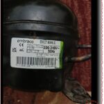
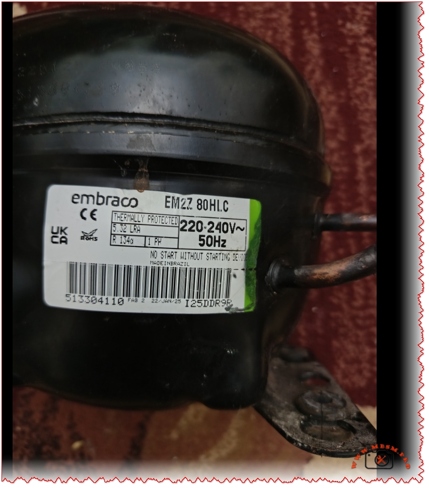
Embraco EM2Z 80HL.C compressor requires approximately 150 ml Oil
Category: Refrigeration
written by www.mbsmpro.com | January 5, 2026
The Embraco EM2Z 80HL.C compressor requires approximately 150 ml (5.07 fl. oz.) of oil. The correct oil type is Polyolester (POE) with a viscosity of ISO 10, designed for use with R134a refrigerant.
Mbsmpro.com, Compressor, Embraco, EM2Z 80HL.C, 1/4 hp, R134a, 220-240V, 50Hz, LBP, 150ml Oil, Made in Brazil
Meta Description: Discover detailed specifications for the Embraco EM2Z 80HL.C compressor. 1/4 HP, R134a, 220-240V 50Hz, LBP with 150ml POE oil capacity. Comprehensive technical analysis and comparisons on Mbsmpro.com.
Excerpt: The Embraco EM2Z 80HL.C is a robust hermetic reciprocating compressor engineered for refrigeration efficiency. Featuring a 1/4 HP motor and optimized for R134a refrigerant, this Brazilian-made unit delivers reliable Low Back Pressure (LBP) performance. This guide details its 150ml oil charge, electrical specs, and competitive advantages for technicians.
The Engineering Standard: Embraco EM2Z 80HL.C Technical Analysis
In the demanding world of commercial and domestic refrigeration, the Embraco EM2Z 80HL.C stands out as a reliable workhorse. Manufactured in Brazil, this hermetic reciprocating compressor is designed to meet the rigorous standards of modern cooling appliances. As refrigeration technicians seek precise data for repairs and replacements, understanding the core specifications of the EM2Z series becomes paramount for ensuring system longevity and efficiency.
This unit is specifically calibrated for Low Back Pressure (LBP) applications, making it an ideal choice for freezers, refrigerators, and display cabinets that require consistent temperature maintenance between -35°C and -10°C.
Detailed Technical Specifications
The EM2Z 80HL.C utilizes a high-efficiency motor configuration compatible with 220-240V at 50Hz power sources. Its internal architecture balances displacement with energy consumption, offering a streamlined solution for 1/4 HP refrigeration circuits.
Specification Category
Technical Data
Brand
Embraco (Nidec)
Model
EM2Z 80HL.C
Refrigerant
R134a (Tetrafluoroethane)
Displacement
6.76 cm³ (approx.)
Horsepower (HP)
1/4 HP (Light) / 1/5 HP (Heavy)
Voltage/Frequency
220-240V ~ 50Hz
Application
LBP (Low Back Pressure)
Evaporating Range
-35°C to -10°C (-31°F to 14°F)
Motor Type
RSIR / RSCR (Check Starting Device)
Locked Rotor Amps (LRA)
5.32 A
Oil Charge Quantity
150 ml (5.07 fl. oz.)
Oil Type
Ester (POE) ISO 10
Expansion Device
Capillary Tube
Cooling Capacity
~170 – 190 Watts (ASHRAE LBP)
Origin
Made in Brazil
Critical Lubrication Guidelines
One of the most frequent inquiries regarding the EM2Z 80HL.C involves its lubrication requirements. This compressor is factory-charged with 150 ml of Polyolester (POE) oil.
Technicians must strictly adhere to this quantity and oil type. R134a refrigerant requires POE oil due to its chemical miscibility properties. Using mineral oil or alkylbenzene will result in system failure, as these oils do not transport correctly with HFC refrigerants, leading to oil logging in the evaporator and eventual compressor seizure. The ISO 10 viscosity rating ensures the lubricant remains fluid enough to return to the compressor even at low evaporating temperatures.
Comparative Market Analysis
When evaluating the Embraco EM2Z 80HL.C, it is useful to compare it against similar compressors in the 1/4 HP, R134a LBP category. The table below highlights how it stacks up against competitors from Secop (Danfoss) and Tecumseh.
Feature
Embraco EM2Z 80HL.C
Secop (Danfoss) TL5G
Tecumseh THG1365Y
Nominal HP
1/5+ to 1/4 HP
1/6+ to 1/5 HP
1/5 HP
Displacement
6.76 cm³
5.08 cm³
5.90 cm³
Voltage
220-240V 50Hz
220-240V 50Hz
220-240V 50Hz
Efficiency (COP)
High
Standard
Standard
Motor Tech
RSIR/RSCR
RSIR/CSIR
PTCS_CR
Oil Type
POE ISO 10
POE
POE
Note: The EM2Z 80HL.C often provides a slightly higher displacement than standard “light” 1/5 HP models, bridging the gap toward a full 1/4 HP performance.
Installation and Service Best Practices
For optimal performance, the EM2Z 80HL.C should be installed with a clean, moisture-free system. The POE oil is highly hygroscopic (absorbs moisture), so the compressor plugs should only be removed immediately before brazing.
Vacuum Deeply: Ensure the system is evacuated to at least 500 microns to remove all moisture that could react with the POE oil.
Starting Device: This model explicitly states “No Start Without Starting Device.” Ensure the original relay and overload protector (or approved replacements) are used to prevent winding damage.
Condenser Airflow: As a static or fan-cooled unit, ensure the condenser is free of dust to maintain the head pressure within design limits, preserving the relatively small 5.32 LRA motor from thermal stress.
Tags: Mbsmgroup, Mbsm.pro, mbsmpro.com, mbsm, Embraco, EM2Z 80HL.C, Compressor Oil Capacity, R134a Compressor, Refrigerator Repair, HVAC Technician, Compressor Datasheet, POE Oil, 1/4 HP Compressor, Made in Brazil, 220V 50Hz
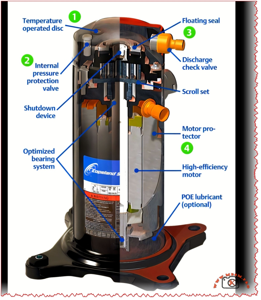
When most technicians open a scroll compressor casing, they’re looking for obvious problems—oil leaks, corrosion, burned-out motor windings. But the real engineering lives in the internal mechanisms you can’t see at first glance: the floating seal that prevents catastrophic vacuum damage, the motor protector that monitors both temperature and amperage, the pressure relief valve that dumps hot gas before the motor fails, and the discharge check valve that prevents high-speed reverse rotation. Understanding these five core components transforms your diagnostic confidence and explains why scroll compressors have outlasted reciprocating designs in millions of air conditioning and refrigeration systems worldwide.
The Floating Seal: The Most Misunderstood Protection Feature
Ask ten HVAC technicians what a floating seal does, and you’ll likely get six different answers. The floating seal’s true function is elegant and critical: it separates the high-pressure discharge side from the low-pressure suction side, and more importantly, it prevents the compressor from drawing into a deep vacuum that would short and destroy the Fusite electrical terminal.
Here’s how it works in practice. When the compressor starts from rest, pressures are equal on both the discharge and suction sides. The orbiting scroll can’t generate compression force without a pressure differential. The floating seal floats on top of the muffler plate, sitting unloaded. As the scroll set spins and begins compressing, internal pressure builds underneath the seal, pushing it up against the top of the muffler plate. Once that pressure differential forms, the seal seals in metal-on-metal contact, creating the separation between high and low side gas. Oil maintains this seal by coating the metal-to-metal interface—not a traditional elastomer gasket.
The vacuum protection aspect is equally important. If a system loses refrigerant charge, or if expansion device blockage prevents suction gas from entering the compressor, the orbiting scroll will keep spinning but won’t find anything to compress. This creates a vacuum on the suction side. Without a floating seal, that vacuum would pull the electrical terminal inward, rupturing it and causing immediate motor failure. The floating seal unloads (separates) when the compression ratio exceeds a critical threshold—typically around 20:1 for ZS and ZF series compressors, and 10:1 for ZB, ZH, ZO, ZP, and ZR series.
When the scrolls are unloaded (separated), the compressor continues to run—it’s spinning without pumping. This is actually a built-in safety feature. Instead of watching the amp meter spike and the motor overheat, the scroll set simply separates, the motor protector monitors rising internal temperature, and the internal overload opens after several minutes, shutting down the compressor before permanent damage occurs.
Common field mistake: Technicians sometimes see a compressor running without building discharge pressure and assume internal failure. In reality, the floating seal has unloaded due to a system issue like low charge, evaporator icing, or a blocked suction line. The real problem isn’t the compressor—it’s upstream.
Motor Protector: Dual Sensing for Maximum Safety
A scroll compressor’s internal motor protector doesn’t work like a traditional overload relay on a reciprocating unit. It’s not just a thermal device sitting in the motor windings. The Copeland motor protector senses both internal shell temperature and amperage simultaneously.
When either temperature OR current exceeds a preset limit, the protector opens an electrical circuit at the terminal box, breaking line voltage and shutting down the compressor. The trip current is typically rated at 103+ amps in a 3-10 second window for overload conditions.
The temperature sensing is particularly clever. The protector monitors discharge plenum temperature—the hot space at the top of the shell where compressed discharge gas collects. When that temperature reaches approximately 250–270°F on most residential and light commercial Copeland models, the protector begins its trip sequence.
Why dual sensing matters: A system with a blocked condenser coil might create high discharge temperatures but normal running current. A system with oil flooding the crankcase might create high current draw with initially normal temperatures. By monitoring both parameters, the motor protector catches problems that single-parameter protection would miss.
Reset behavior is intentional and important. Once tripped, the motor protector requires the compressor to cool down—typically 30 minutes to several hours depending on ambient temperature and how severely the protector was triggered. Technicians who restart a compressor immediately after a motor protector trip often trigger it again within seconds. The cooling-off period allows internal temperature to equalize and motor windings to stabilize, giving an accurate diagnosis of what caused the original trip.
Discharge Check Valve: Silent Guardian Against Destruction
Reciprocating compressors use suction and discharge reed valves inside the piston head—moving parts that open and close thousands of times per minute. Scroll compressors eliminate those moving parts entirely, which is why they’re so quiet. But they still need protection against one specific catastrophe: if a compressor shuts down with high-pressure discharge gas trapped in the shell, and system pressures suddenly drop, that gas will backflow and drive the orbiting scroll in reverse at extremely high speed—potentially 10+ times faster than normal rotation speed.
The discharge check valve prevents this by closing the moment discharge pressure drops below suction pressure. The valve is beautifully simple: a free-floating disc that sits in a valve cage, held open by discharge gas flow during normal operation.
When the compressor stops, discharge flow stops immediately. Without that forward pressure, the disc falls away from its seat (aided by gravity and internal backflow pressure) and closes the discharge port. The design is nearly foolproof because:
The disc has low surface contact area with the seat, so even if oil-coated, gravity and backflow force overcome adhesion.
The disc is protected inside a cage that shields it from normal gas pulsations and vibration, preventing chatter.
It requires zero external maintenance—completely sealed and internal.
The cost is minimal (a stamped metal disc and simple cage), the benefit is enormous (prevention of scroll separation and shaft bearing damage). This is engineering economics at its finest.
Internal Pressure Relief & Temperature Operated Disc: The Redundant Safety Stack
Scroll compressors stack multiple independent safety devices, each with its own trigger point and response. This redundancy prevents the single-point failure that can plague simpler designs.
Internal Pressure Relief Valve (IPR)
The IPR is a spring-loaded valve set to open at a specific differential pressure between discharge and suction. For R-22 applications, this is typically 400 ± 50 psi differential. For R-410A, the threshold is higher at 500–625 psi differential.
When pressure builds beyond this differential (a sign that system pressures are dangerously high), the IPR opens. Instead of venting to the outside, it opens a passage that directs high-pressure gas into the suction side of the compressor, near the motor protector. This sudden injection of hot discharge gas raises shell temperature, triggering the motor protector to open line voltage and shut down the compressor.
Temperature Operated Disc (TOD)
While the IPR responds to pressure, the TOD responds to temperature. The TOD is a bimetallic disc sensitive to discharge gas temperature. On most Copeland ZRK and ZR series compressors, it opens at approximately 270°F.
When discharge temperature climbs (a sign of high compression ratios, lack of cooling, or system inefficiency), the TOD opens and channels hot discharge gas toward the motor protector, causing shutdown.
The redundancy is intentional. A system with a blocked discharge line might trigger the pressure relief. A system with low refrigerant charge and high superheating might trigger the temperature disc. A system with both problems simultaneously will be caught by whichever threshold is reached first.
Scroll Set & Orbiting Design: The Compression Heart
The scroll set consists of two spiral-shaped scrolls—one fixed to the compressor frame, one orbiting around the center. Unlike reciprocating pistons that move linearly, the orbiting scroll makes a circular orbit while maintaining a fixed angular orientation. This continuous motion is what generates the characteristic smoothness of scroll operation.
As the orbiting scroll moves around the fixed scroll, it creates expanding and contracting pockets of refrigerant. Gas enters at the outer edge through the suction port, gets trapped, and as the orbiting scroll continues its orbit, those pockets shrink and move toward the center, compressing the gas. Compressed gas exits through the center discharge port.
The scroll design offers several inherent advantages over reciprocating:
Continuous compression with no unloading/reloading cycle reduces vibration to one-fifth that of reciprocating units (0.2 bar pulsation vs 2.5 bar).
Smooth torque delivery with minimal torque ripple, reducing mechanical stress on motors and couplings.
No suction or discharge valve losses because there are no moving valves inside the scroll set itself—only the discharge check valve external to the set.
Axial and radial compliance in modern designs allows the scrolls to shift slightly under load, accommodating liquid refrigerant without immediate damage (a capability that’s saved countless systems from catastrophic failure).
Optimized Bearing System: Friction Reduction for Efficiency
One of the most overlooked innovations in modern scroll compressors is bearing design. Conventional scroll compressors used traditional PTFE (Teflon) bush bearings supporting the orbiting scroll journal. Newer designs—particularly in high-speed variable compressors—have moved to outer-type bush bearings made from engineering plastics without back steel layers, combined with female-type eccentric journals.
This seemingly small change delivers significant gains:
Reduced bearing loads through optimized eccentric journal geometry, lowering friction losses across all operating conditions.
Lower friction coefficient of the new bearing material vs traditional PTFE, particularly in the hydrodynamic lubrication region where most scroll compressors operate.
More compact design, with shaft length reduced by ~8% and overall compressor envelope smaller by ~20%.
Efficiency improvement of 5%+ at rated conditions, with even greater gains at low-speed and high-speed operation.
Reduced noise by minimizing the excitation moment caused by orbiting scroll centrifugal force and gas forces.
The bearing system also supports higher maximum operating speeds (up to 165Hz expansion in some designs) without bearing fatigue, enabling manufacturers to offer variable-speed scroll compressors that can modulate capacity from 10% to 100%.
High-Efficiency Motor Design & POE Lubricant
Modern Copeland and other premium scroll compressors feature redesigned motor windings optimized for lower copper losses and better heat dissipation. The suction gas returning to the compressor passes through the motor windings, cooling them directly—a passive cooling mechanism that becomes more effective as system load increases.
When system designers specify POE (polyol ester) lubricants for R-410A or HFC refrigerant applications, they’re trading simplicity for efficiency. POE oils are excellent lubricants—superior to mineral oils in cooling capacity and chemical stability. But they’re hygroscopic: they absorb moisture from air at roughly 200 ppm per hour of exposure.
This creates a strict maintenance protocol: system components with POE oil must not remain exposed to ambient air for more than 3 minutes during service. Why? Water contamination in scroll compressor oil leads to acid formation, copper plating, bearing corrosion, and eventual motor failure. Technicians must have evacuation equipment ready, refrigerant recovery systems standing by, and a clear service plan before opening any POE-based system.
Scroll vs. Reciprocating: The Performance Reality
The marketing says scroll compressors are “more efficient.” What does that mean in practical terms?
The efficiency advantage isn’t just a marketing claim—real-world installations show scroll systems reducing annual power consumption by 18% compared to reciprocating at the same capacity. Over a 15-year equipment life at commercial electricity rates, that’s a significant operating cost reduction.
The tradeoff? Scroll compressors cost more upfront and are less forgiving of abuse. A reciprocating compressor can tolerate slight liquid slugging or mild refrigerant overcharge. A scroll compressor will suffer damage faster under identical conditions. This is why proper system design, charge verification, and preventive maintenance are non-negotiable with scroll technology.
Field Diagnostics: What Internal Components Tell You
When a scroll compressor fails or shuts down unexpectedly, the internal components leave diagnostic clues.
High discharge temperature causing shutdown
If your gauges show discharge pressure normal but the compressor shuts down on the motor protector, suspect the temperature operated disc. Check system superheat, confirm the condenser coil is clean, verify proper refrigerant charge, and look for restrictions. The TOD is doing its job—you’ve got an upstream problem.
Low discharge pressure with the compressor running
The floating seal has unloaded. This happens when the compression ratio exceeds the design limit (usually above 10:1). Check for:
Refrigerant undercharge (most common)
Evaporator blockage or icing
Suction filter clogging
Bad expansion device
Compressor running but no cooling
The orbiting scroll is spinning but the scroll set isn’t compressing. Either the floating seal is unloaded, or more rarely, the scroll set itself has worn beyond tolerance. Let the unit cool, then check whether it pumps during restart.
This is catastrophic and irreversible. If a scroll compressor is ever observed rotating backwards (a technician witnesses it at startup, or you see the telltale reverse-rotation noise), the discharge check valve has failed. The orbiting scroll bearing system has been damaged. Replace the compressor—there’s no repair path.
Why Component Design Drives Long-Term Reliability
Every internal component described in this article serves a purpose: the floating seal enables low-torque starting and vacuum protection, the motor protector provides dual-parameter safety, the discharge check valve prevents reverse-rotation destruction, the pressure relief and temperature disc create redundant protection, the bearing system minimizes friction and noise, and the scroll set’s continuous compression delivers efficiency and smoothness.
Manufacturers didn’t add these features by accident. Each one solves a real failure mode observed in thousands of field installations. When you understand why each component exists and what it prevents, you become a better diagnostician and a more confident technician. You stop guessing and start thinking—and that’s how customer satisfaction and system longevity are actually achieved.
Focus Keyphrase (Yoast SEO – 191 characters maximum)
“Scroll compressor internal components floating seal motor protector discharge check valve pressure relief temperature disc explained”
SEO Title (60 characters maximum)
“Scroll Compressor Internal Components & Safety Features Explained”
Meta Description (160 characters maximum)
“Understand scroll compressor internal protection: floating seal, motor protector, discharge check valve, pressure relief, and temperature disc. Why each component matters.”
When technicians open a scroll compressor casing, the real engineering lives in internal mechanisms invisible at first glance: the floating seal preventing vacuum damage, the motor protector monitoring temperature and amperage, the pressure relief valve, the discharge check valve preventing reverse rotation, and the optimized bearing system. Understanding these core components transforms your diagnostic confidence.
The Donper K400CZ1 is a hermetic reciprocating compressor designed for commercial refrigerators and chest freezers operating with refrigerant R134a on 220‑240V 50Hz single‑phase power. It offers roughly 1/2 hp class performance with about 400 W cooling capacity, making it suitable for medium‑size display cabinets and storage equipment in supermarkets and restaurants.
Nameplate data and technical profile
Item
Donper K400CZ1 value
Source
Brand
Donper
Model
K400CZ1
Refrigerant
R134a
Rated voltage
220‑240V 50Hz, 1‑phase
Application range
LBP commercial refrigeration (freezers, show cases)
Nominal capacity
≈ 400 W at LBP operating conditions
Approximate horsepower class
1/2 hp+
Cooling method
Static or forced‑air condenser, hermetic motor cooling by suction gas
Motor type
RSCR or CSIR with external start components (regional variants)
Thermal protection
Internal motor protector (thermally protected)
This Donper K400CZ1 sits in the upper range of the brand’s R134a low‑back‑pressure line, intended for evaporating temperatures typically between −30 °C and −10 °C in commercial freezers.
Applications and operating envelope
Commercial chest freezers and island freezers that require robust starting torque and 24/7 duty under supermarket conditions.
Glass door merchandisers and cake displays, where stable temperature and quiet operation are important along with compact compressor dimensions.
Cold drink dispensers and reach‑in cabinets using capillary tube expansion, designed around R134a and LBP conditions in the Donper catalog.
Typical operating envelope for K‑series R134a LBP compressors:
Parameter
Typical K‑series R134a LBP range*
Evaporating temperature
−35 °C to −5 °C
Condensing temperature
40 °C to 55 °C
Ambient temperature
32 °C to 43 °C
Return gas temperature
20 °C max
*Values based on Donper R134a LBP catalog ranges; check the official selection software or sheet for exact K400CZ1 limits before system design.
Comparison with other Donper R134a models
To position the K400CZ1 inside the R134a portfolio, the next table compares it with smaller and larger Donper models used in similar equipment.
Model
Refrigerant
Voltage
Capacity class
Typical application
Comment
L65CZ1
R134a
220‑240V 50Hz
≈ 1/6 hp
Small vertical cooler or minibar
Low power, very efficient, light load.
S72CZ1
R134a
220‑240V 50Hz
≈ 1/4 hp
Under‑counter refrigerator
Balanced between energy and capacity; referenced on Mbsm.pro.
K375CZ1
R134a
220‑240V 50Hz
≈ 1/3–3/8 hp
Medium freezer or chiller
Frequently used as predecessor to K400CZ1.
K400CZ1
R134a
220‑240V 50Hz
≈ 1/2 hp+ (400 W)
Chest freezer, island cabinet
Higher pull‑down capacity for larger volume.
NE6210CZ (Donper commercial)
R134a
220‑240V 50Hz
≈ 3/8 hp
High‑end merchandiser
Advanced efficiency, similar duty but different platform.
This comparison shows how K400CZ1 extends the LBP range toward heavier commercial loads while keeping compatibility with standard R134a capillary tube systems.
Performance and efficiency considerations
For Donper R134a compressors working at 220‑240V 50Hz LBP, the cooling capacity range spans roughly 239–1365 Btu/h, with corresponding COP values optimized for supermarket duty.
A 400 W LBP compressor typically delivers COP values around 1.3–1.6 under ASHRAE 7.2/35/54 °C conditions in this power range, similar to competing hermetic brands.
When compared with equivalent Embraco R134a LBP compressors of about 1/2 hp, K‑series Donper units generally offer comparable capacity and current draw, while often being more competitive in price for OEMs and aftermarket replacement.
Installation, start components and reliability
Donper specifies the use of properly matched start relays and run capacitors (for RSCR/CSIR motors) to guarantee reliable starting at low evaporating temperatures and high condensing temperatures.
Internal motor protection is calibrated to trip on high winding temperature or locked‑rotor current, helping to protect against fan failure, condenser clogging or incorrect voltage.
For long‑life operation, manufacturers recommend adequate airflow over the condenser, correct refrigerant charge, clean capillary filters and vibration‑isolating mounting grommets to protect the hermetic shell and discharge line.
Compared with smaller domestic compressors, K400CZ1 is more sensitive to poor ventilation and dirty condensers because it works closer to its maximum envelope in heavy commercial duty; preventive maintenance is therefore critical to avoid overheating and nuisance trips.
Yoast SEO fields for WordPress
Focus keyphrase (≤191 characters) Donper K400CZ1 compressor, R134a 1/2 hp 400 W, 220‑240V 50Hz LBP, commercial refrigerator and chest freezer hermetic compressor, static cooling, Mbsmpro technical data
SEO title Donper K400CZ1 R134a 1/2 hp Compressor – 400 W LBP Commercial Freezer Solution | Mbsmpro.com
Meta description Discover the Donper K400CZ1 R134a 1/2 hp compressor: 400 W cooling capacity, 220‑240V 50Hz LBP design for chest freezers and merchandisers, with technical data, comparisons and installation notes for professional HVAC use.
Excerpt (first 55 words) The Donper K400CZ1 is a hermetic reciprocating compressor designed for commercial refrigerators and chest freezers operating with refrigerant R134a on 220‑240V 50Hz single‑phase power. It offers roughly 1/2 hp class performance with about 400 W cooling capacity, making it suitable for medium‑size display cabinets and storage equipment in supermarkets and restaurants.
Mbsmpro.com, HVAC, CBB65 SH, 50 µF, 450 VAC, Capacitor Explosion, Start Run Capacitor Failure, Causes, Diagnosis, Protection, Air Conditioner
Why HVAC capacitors explode
An AC motor run capacitor such as the CBB65 SH usually explodes when it is forced to work beyond its electrical or thermal limits, or when the start‑assist components fail and leave it in the circuit too long. This overstress breaks down the internal dielectric, creates gas and pressure, and finally ruptures the metal can or plastic top.
Main electrical causes
Overvoltage on the supply line: When the real working voltage is higher than the 450 VAC rating, the electric field in the capacitor becomes too strong, puncturing the dielectric and causing an internal short that can end in a violent burst. Power surges, lightning and unstable grids are typical sources of this problem in residential and light commercial HVAC systems.
Start capacitor or potential relay failure: In systems that use a start‑assist (start capacitor + potential relay or PTC thermistor), a failed relay can keep the start capacitor in series with the run capacitor and motor for too long, overheating the assembly until the weakest capacitor explodes.
Short circuits and wiring errors: Miswiring between C, FAN and HERM terminals, damaged insulation or loose terminals increase current and can create localized heating and arcing at the capacitor lugs, which accelerates internal failure.
Thermal and environmental stress
Overheating from high ambient temperature: Capacitors mounted near hot compressor shells or in outdoor units exposed to direct sun often run above their design temperature, which speeds dielectric aging and raises internal pressure.
Continuous heavy load and long duty cycles: When the compressor or fan runs for long periods because of undersized equipment, dirty condensers or refrigerant leaks, the capacitor carries high ripple current and runs hot, again pushing it toward bulging and rupture.
Poor ventilation inside the control box: A small metal enclosure with no airflow traps heat around the capacitor, especially when several components (contactors, relays, resistors) are mounted close together.
Aging, quality and mechanical factors
Aging of the CBB65 capacitor: Over years of service the polypropylene film and internal connections lose strength; bulging, leaking oil or swelling are classic warning signs just before failure.
Low‑quality components: Cheap capacitors with thin film, poor impregnation and weak safety vents fail much earlier than branded models, and they are more likely to burst instead of opening safely.
Vibration and mechanical damage: If the capacitor is not firmly fixed or is mounted close to vibrating copper tubes, repeated shock can crack the internal connections or case, leading to moisture ingress and eventual explosion.
Effects on the HVAC system
A blown capacitor is not just a bad part; it affects the entire air‑conditioning circuit.
The compressor may hum but not start, draw locked‑rotor current and overheat its windings, risking a burnt motor.
The outdoor fan can stop or run slowly, which increases head pressure and temperature and may trip thermal protection or high‑pressure switches.
Repeated capacitor explosions without proper diagnosis usually indicate deeper issues, such as incorrect voltage, wrong µF size, or a defective start‑assist device.
Comparison: HVAC capacitor failure vs. other AC failures
Failure type
Main symptom
Root cause
Risk level for compressor
Run/start capacitor explosion
Loud pop, oil leak, swollen can, motor will not start or runs weak
Very high: repeated locked‑rotor starts overheat windings
Fan motor failure without capacitor damage
Fan not turning, capacitor tests normal
Worn bearings, open winding
Medium: high head pressure but no electrical blast
Contactor welding closed
Unit runs non‑stop even with thermostat off
Overcurrent, contact wear
High: continuous running overheats compressor and capacitor
Refrigerant leak
Long run time, poor cooling, but capacitor may still test good
Mechanical leak in circuit
Indirect: long run time can overheat and age capacitor faster
How to prevent capacitor explosions
Match voltage and capacitance correctly: Always use replacement capacitors with at least the same voltage rating (for example 450 VAC) and the specified capacitance in µF; undersized or underrated parts are much more likely to fail.
Control supply quality: Installing surge protection, checking for correct line voltage and ensuring solid grounding reduces overvoltage events that can puncture the dielectric.
Replace start‑assist components together: When a start capacitor fails or explodes, replace the potential relay or PTC as well to avoid repeating the fault due to a device that keeps the capacitor in series too long.
Improve cooling and layout: Keep the capacitor away from hot compressor surfaces, add ventilation openings in the control box and avoid tight bundles of heat‑producing parts around it.
Adopt preventive maintenance: Periodic inspection for swelling, leaks, rusted terminals or discoloration allows technicians to change the capacitor early and avoid a violent rupture.
Key values and comparison table
The CBB65 SH capacitor in many residential units is typically a motor run type used for compressor or fan motors. The table compares this typical 50 µF model with other common HVAC capacitors.
Parameter
CBB65 SH run capacitor
Typical start capacitor
Small fan run capacitor
Capacitance
50 µF ±5% (example value)
135–324 µF (wide range)
3–10 µF
Voltage rating
450 VAC
250–330 VAC
370–450 VAC
Duty
Continuous (motor running)
Short‑time start only
Continuous
Construction
Metallized polypropylene, oil‑filled or dry
Electrolytic, non‑polarized
Metallized polypropylene
Typical failure mode
Swelling, leaking, occasional explosion under severe stress
Violent rupture if left in circuit too long
Value drift, open circuit
Yoast SEO elements for this article
Focus keyphrase (≤191 characters) Exploding HVAC capacitor, CBB65 SH 50 µF 450 VAC, causes of capacitor explosion, overvoltage, overheating, start relay failure, air conditioner run and start capacitor protection
SEO title Why the HVAC Capacitor Explodes: CBB65 SH 50 µF 450 VAC Failure Causes and Protection – Mbsmpro.com
Meta description Learn why the CBB65 SH 50 µF 450 VAC capacitor in air conditioners explodes, from overvoltage and overheating to start‑relay faults, plus practical tests and protection tips for safer HVAC systems.
Tags Mbsmgroup, Mbsm.pro, mbsmpro.com, mbsm, HVAC capacitor, CBB65 SH, capacitor explosion, air conditioner repair, start capacitor failure, run capacitor failure, overvoltage protection, compressor not starting, AC maintenance
Excerpt (first 55 words) An AC motor run capacitor such as the CBB65 SH usually explodes when it is forced to work beyond its electrical or thermal limits, or when the start‑assist components fail and leave it in the circuit too long. This overstress breaks down the dielectric, creates internal gas and pressure, and finally ruptures the can.