Understanding Active and Passive Electronic Components
Electronic circuits are built from two main families of components: active components that can amplify or control signals, and passive components that only store, dissipate, or filter energy. Recognizing which parts are active or passive is essential for troubleshooting PCBs, designing power supplies, and analyzing why a control board fails in HVAC or refrigeration equipment.
What makes a component active or passive?
Active components require an external power source and can introduce energy into the circuit, typically by amplifying, switching, or processing signals. Passive components do not generate power; instead, they resist, store, or transfer energy, which makes them simpler and generally more reliable over long operating hours.
Key criteria
Criterion
Active components
Passive components
Power requirement
Need external bias or supply to operate correctly
Operate without dedicated supply; work from the circuit itself
Signal behavior
Can amplify, modulate, or switch signals
Cannot amplify; only attenuate, store, or filter
Typical role
Processing, logic, regulation, high‑level control
Biasing, timing, filtering, matching, energy storage
Active devices are the “intelligent” part of a board: they decide when current flows, how much gain is applied, and how digital data is processed. In low‑voltage control boards for compressors or fan motors, these parts are usually the first suspects when there is no response or unstable regulation.
Common active components
Active component
Function in a circuit
Typical HVAC / industrial example
Transistor (BJT, MOSFET)
Amplifies or switches current; acts as electronic valve
Driving a relay coil, controlling DC fan speed
Diode
Allows current in one direction only; used for rectification and protection
Bridge rectifier in SMPS, free‑wheel diode on solenoid
LED (light emitting diode)
Indicates status by emitting light when forward‑biased
Power, alarm, or compressor‑run indicators
Photodiode
Converts light into current; used in sensors and receivers
Infrared receiver in remote control boards
Integrated circuit (IC)
Combines many transistors/diodes into one package for logic, control, or power conversion
Microcontroller, driver IC, or op‑amp in control module
Seven‑segment display (LED)
Numeric indicator built from multiple LEDs driven by an IC
Temperature or error‑code display on controllers
Rechargeable/non‑rechargeable battery
Provides DC supply for memory backup or standalone devices; considered active in many classifications because it delivers energy into the circuit
RTC backup battery or wireless sensor power source
Compared with simple mechanical switches, active devices react faster, allow precise analog control, and integrate protection features such as soft‑start or current limiting.
List of passive components and their behavior
Passive components shape voltage and current waveforms, store energy, and protect sensitive active devices from surges and noise. Without properly sized passive parts, even the best microcontroller will fail due to ripple, spikes, or thermal stress.
DC bus smoothing, EMI filtering, start/run capacitors
Inductor
Stores energy in magnetic field; filters current or forms resonant circuits
Output choke in DC‑DC converter, EMI filter
Switch (mechanical)
Opens or closes circuit path manually or by actuator
On/off pushbuttons, limit switches
Variable resistor / potentiometer
Adjustable resistance for calibration or user settings
Set‑point knob on thermostat or speed control
Transformer
Transfers energy between windings; adapts voltage and provides isolation
Mains step‑down transformer, control transformer
Passive parts rarely fail catastrophically; instead, their values drift with heat, age, or overload, which can slowly push a regulation loop out of tolerance.
Active vs passive: practical comparisons
A good way to understand the difference is to compare how active and passive components behave in typical low‑voltage control circuits. This is especially relevant when diagnosing PCB faults in refrigeration controllers or inverter drives.
Energy and control capabilities
Aspect
Active component example
Passive component example
Signal amplification
Transistor boosting sensor signal before ADC
No amplification; resistor network only scales sensor voltage
Switching function
MOSFET turning compressor relay on/off using low‑power logic signal
Toggle switch manually interrupts line but cannot be gated electronically
Power gain
Audio or gate driver IC increases output power vs. input
Transformer changes voltage and current but does not create power gain
Dependence on supply
Stops functioning without bias or Vcc
Still presents resistance, capacitance, or inductance characteristics without dedicated supply
In digital control boards, active devices act as the brain, while passive parts form the skeleton and blood vessels that route and condition energy so the brain can work reliably.
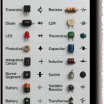
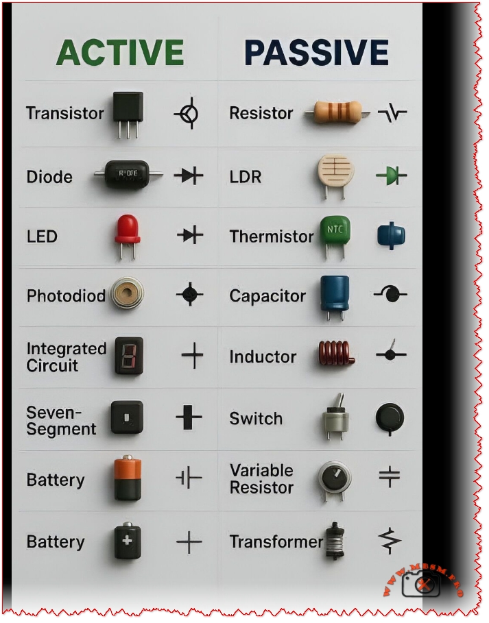
Component symbols and schematic reading
Every component is represented by a standardized symbol on schematics, which allows engineers and technicians to understand complex boards quickly. Learning these symbols is critical for decoding service manuals, drawing custom circuits, or reverse‑engineering a defective PCB.
Representative symbols
Component
Typical symbol characteristics
Transistor
Three‑terminal symbol (emitter, base, collector or source, gate, drain) with arrow indicating current direction
Diode / LED / photodiode
Triangle‑to‑bar symbol; LED adds outward arrows; photodiode adds inward arrows
Resistor / variable resistor
Zig‑zag or rectangular symbol; arrow or extra terminal for variable types
Capacitor
Two parallel lines (or one curved for polarized electrolytic)
Inductor
Series of loops or rectangles; transformer shows two inductors with coupling bars or core symbol
LDR / thermistor
Resistor symbol with diagonal arrows or small temperature mark to indicate dependency
Knowing the symbol set reduces troubleshooting time because it becomes easy to identify where signals are amplified, rectified, filtered, or limited on any board.
Why both active and passive parts are essential in modern electronics
Real‑world products, from inverter air conditioners to smart thermostats, rely on the interplay between active controllers and passive networks. Active components process information and drive loads, while passive components ensure clean power, stable references, and EMC compliance.
In a typical microcontroller‑based board:
The microcontroller, transistors, and driver ICs handle logic, timing, and switching.
Resistors, capacitors, and inductors form power filters, RC timing networks, and snubbers to protect the active silicon.
Sensors such as thermistors and LDRs translate physical variables into electrical signals that the active devices can interpret.
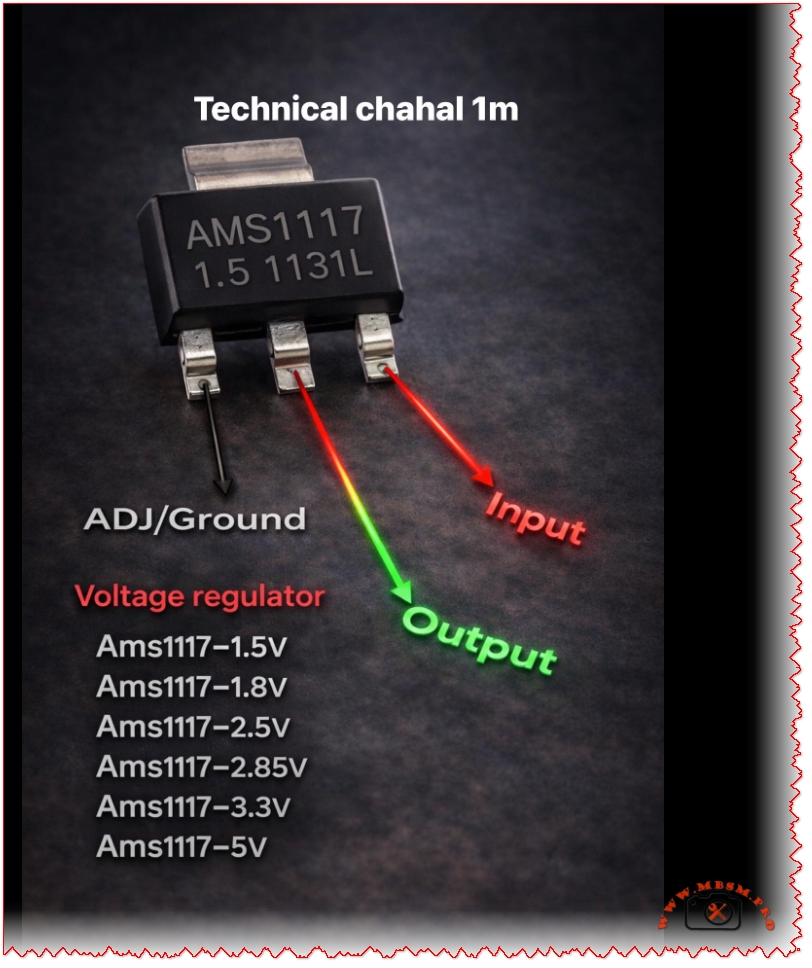
AMS1117 Voltage Regulator Pinout and Versions: Complete Guide for Electronics Projects
The AMS1117 family is one of the most widely used linear regulators for stepping down DC voltages in embedded and DIY electronics projects. Its simple three‑pin layout and multiple fixed output versions make it an excellent choice for powering microcontrollers, sensors, and communication modules.
AMS1117 overview
The AMS1117 is a low‑dropout (LDO) linear voltage regulator capable of delivering up to 1 A of continuous current, depending on heat dissipation and PCB design.
It is available as fixed‑output regulators (1.5 V, 1.8 V, 2.5 V, 2.85 V, 3.3 V, 5 V and others) and as an adjustable version that can be set from about 1.25 V to 12 V using external resistors.
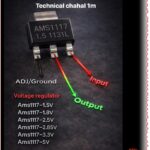
Pinout: input, output, and ground/ADJ
In the common SOT‑223 package, the pins from left to right (front view, text facing you) are ADJ/GND, OUTPUT, and INPUT.
For fixed versions (such as AMS1117‑3.3 or AMS1117‑5.0), the first pin is tied to ground, while for the adjustable version it is used as the ADJ pin to set the output voltage with a resistor divider.
Fixed output AMS1117 variants
The table below summarizes popular fixed‑voltage versions and typical use cases.
AMS1117 version
Nominal output
Typical application example
AMS1117‑1.5
1.5 V
Low‑voltage ASICs, reference rails
AMS1117‑1.8
1.8 V
ARM cores, SDRAM, logic ICs
AMS1117‑2.5
2.5 V
Older logic families, ADC/DAC rails
AMS1117‑2.85
2.85 V
Mobile RF, modem chipsets
AMS1117‑3.3
3.3 V
MCUs, sensors, 3.3 V logic from 5 V sources
AMS1117‑5.0
5.0 V
Regulating from 7–12 V to 5 V logic or USB lines
Electrical characteristics and design tips
The typical input range for AMS1117 regulators is up to 12–15 V, with a dropout voltage around 1.1–1.3 V at 1 A, meaning the input must be at least about 1.3 V higher than the desired output.
For stable operation, manufacturers recommend small bypass capacitors at both input and output (for example 10 µF electrolytic or tantalum), which help reduce noise and improve transient response in digital circuits.
Typical applications in embedded systems
AMS1117 regulators are frequently used to derive 3.3 V from 5 V USB or 9–12 V adapter inputs in Arduino‑style development boards and sensor modules.
Thanks to built‑in thermal shutdown and short‑circuit protection in many implementations, these regulators offer a robust solution for compact PCBs, IoT nodes, and hobby electronics where space and simplicity are critical.
The Ultimate Guide to Zener Diode Series: From 1N746 to 1N5369
In the intricate world of electronic circuit design, few components are as simultaneously simple and vital as the Zener diode. Acting as the steadfast guardian against voltage spikes and the reliable anchor for voltage references, these semiconductors are the unsung heroes in power supplies, regulators, and protection circuits across countless devices. Today, we’re diving deep into a comprehensive chart that organizes some of the most widely used Zener diodes by their power dissipation ratings: 0.5 Watt, 1 Watt, and 5 Watt.
Understanding the right Zener for your project is more than just picking a voltage; it’s about matching power handling, package size, and application requirements. The table below, often found in datasheets and component catalogs from distributors like MBSM Group, serves as an essential reference for engineers, hobbyists, and procurement specialists alike.
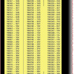
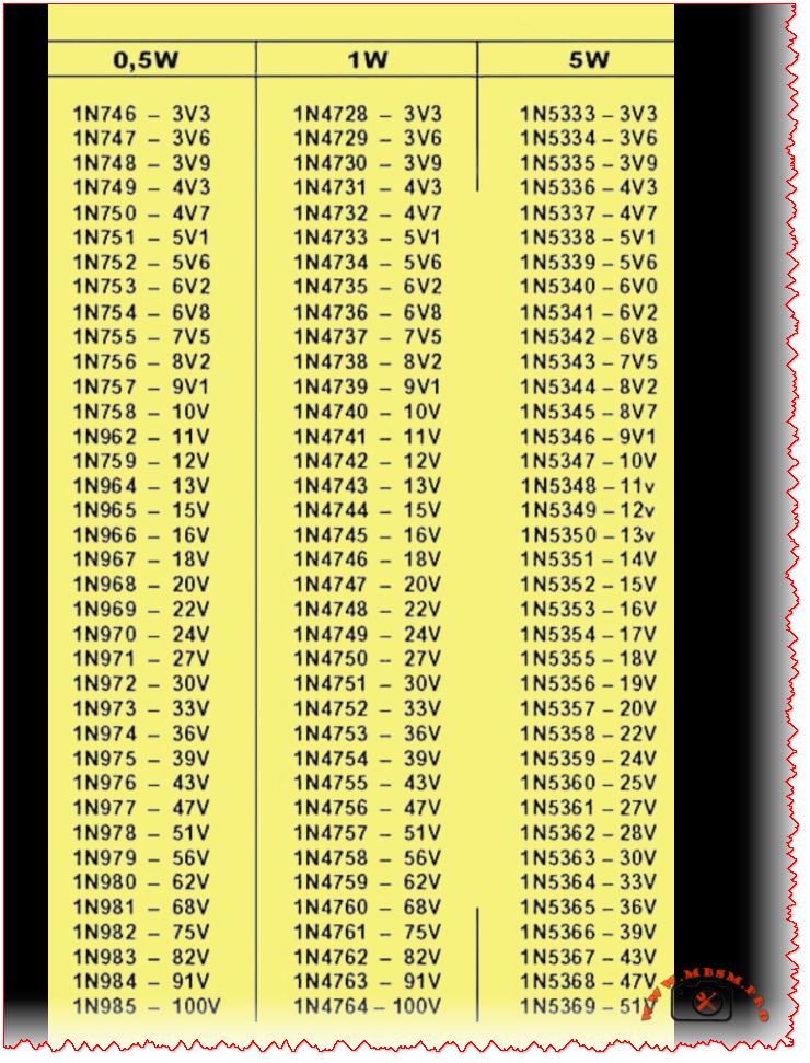
Zener Diode Voltage & Part Number Reference Chart
The following table cross-references three major Zener diode families, organized by their nominal Zener voltage. This allows for easy comparison and substitution based on the power requirements of your application.
0.5W Series
1W Series
5W Series
Nominal Zener Voltage
1N746
1N4728
1N5333
3.3V
1N747
1N4729
1N5334
3.6V
1N748
1N4730
1N5335
3.9V
1N749
1N4731
1N5336
4.3V
1N750
1N4732
1N5337
4.7V
1N751
1N4733
1N5338
5.1V
1N752
1N4734
1N5339
5.6V
1N753
1N4735
1N5340
6.0V / 6.2V*
1N754
1N4736
1N5341
6.8V
1N755
1N4737
1N5342
7.5V
… (and so on, up to 100V)
*Note: Minor discrepancies can occur between series; the 1N5340 is commonly listed as 6.0V, while the 0.5W/1W equivalents are 6.2V. Always consult the specific datasheet.*
Decoding the Ratings: 0.5W vs. 1W vs. 5W
So, what’s the real-world difference between these series? It boils down to power dissipation and physical size.
0.5W Series (e.g., 1N746-1N985): These are typically housed in small glass DO-35 packages. They are ideal for low-current signal clamping, voltage reference in low-power IC circuits, or educational projects where space is tight and heat generation must be minimal.
1W Series (e.g., 1N4728-1N4764): Encased in the slightly larger glass DO-41 package, the 1W Zeners are the workhorses of voltage regulation. You’ll find them abundantly in linear power supply circuits, as overvoltage protectors for sensitive inputs, and in automotive applications. They offer a robust balance of capability and size.
5W Series (e.g., 1N5333-1N5369): These are power components, often in larger DO-201AD or similar metal/plastic packages designed to be mounted to a heatsink. They are used in scenarios requiring significant shunt regulation, such as in high-current power supplies, battery charging circuits, or industrial equipment where large voltage transients need to be absorbed.
Choosing the correct series is critical. Using a 0.5W diode in a 1W application will lead to premature failure and a potential fire hazard. Conversely, using a 5W diode where a 0.5W would suffice is an inefficient use of board space and budget.
Practical Applications in Circuit Design
How are these components used? Let’s look at two classic examples:
Voltage Regulation: A 1N4733A (5.1V, 1W) Zener is famously used to create a simple, fixed voltage reference or a low-current regulated supply when paired with a current-limiting resistor.
Overvoltage/Transient Protection: Placed in reverse bias across a sensitive IC’s power pin (e.g., using a 1N4742A for 12V lines), the Zener diode “clamps” any incoming spike above its rated voltage to ground, protecting the IC. The higher-power 5W series excel in protecting entire power rails.
Sourcing and Reliable Information
For professionals and enthusiasts looking to source these components or dive into their detailed specifications, reputable distributors and manufacturers’ resources are key. Here are some valuable links:
Image Reference: For clear visual identification of the different packages (DO-35, DO-41, DO-201AD), you can refer to this diode package guide from a trusted educational electronics site: All About Circuits – Diode Packages(Link is safe and leads to a well-known, reputable domain in electronics education.)
Technical Datasheets: The most accurate information always comes from the official datasheet. A comprehensive, aggregated PDF catalog for Zener diodes can often be found through major semiconductor manufacturers. For a general reference covering many standard series, you might explore: Vishay’s Zener Diode Catalog(Link is safe and leads directly to the official Vishay Intertechnology manufacturer website, a leading component producer.) Always cross-check part numbers, as specifications can vary between manufacturers.
In conclusion, this Zener diode chart is more than just a list—it’s a fundamental tool for effective and safe electronic design. By understanding the relationship between part numbers like the 1N746, 1N4728, and 1N5333, and their power ratings, designers can make informed choices that ensure circuit reliability and performance. Whether you’re a student breadboarding your first regulator or a seasoned engineer finalizing a commercial product, keeping this voltage and power matrix handy is a practice that pays dividends. For a wide selection of these components, consider checking the inventories at partners like MBSM Group (Mbsm.pro).