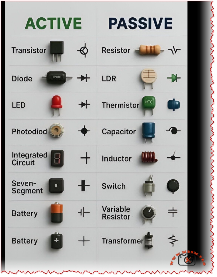
Understanding Active and Passive Electronic Components
Electronic circuits are built from two main families of components: active components that can amplify or control signals, and passive components that only store, dissipate, or filter energy. Recognizing which parts are active or passive is essential for troubleshooting PCBs, designing power supplies, and analyzing why a control board fails in HVAC or refrigeration equipment.
What makes a component active or passive?
Active components require an external power source and can introduce energy into the circuit, typically by amplifying, switching, or processing signals. Passive components do not generate power; instead, they resist, store, or transfer energy, which makes them simpler and generally more reliable over long operating hours.
Key criteria
Criterion
Active components
Passive components
Power requirement
Need external bias or supply to operate correctly
Operate without dedicated supply; work from the circuit itself
Signal behavior
Can amplify, modulate, or switch signals
Cannot amplify; only attenuate, store, or filter
Typical role
Processing, logic, regulation, high‑level control
Biasing, timing, filtering, matching, energy storage
Active devices are the “intelligent” part of a board: they decide when current flows, how much gain is applied, and how digital data is processed. In low‑voltage control boards for compressors or fan motors, these parts are usually the first suspects when there is no response or unstable regulation.
Common active components
Active component
Function in a circuit
Typical HVAC / industrial example
Transistor (BJT, MOSFET)
Amplifies or switches current; acts as electronic valve
Driving a relay coil, controlling DC fan speed
Diode
Allows current in one direction only; used for rectification and protection
Bridge rectifier in SMPS, free‑wheel diode on solenoid
LED (light emitting diode)
Indicates status by emitting light when forward‑biased
Power, alarm, or compressor‑run indicators
Photodiode
Converts light into current; used in sensors and receivers
Infrared receiver in remote control boards
Integrated circuit (IC)
Combines many transistors/diodes into one package for logic, control, or power conversion
Microcontroller, driver IC, or op‑amp in control module
Seven‑segment display (LED)
Numeric indicator built from multiple LEDs driven by an IC
Temperature or error‑code display on controllers
Rechargeable/non‑rechargeable battery
Provides DC supply for memory backup or standalone devices; considered active in many classifications because it delivers energy into the circuit
RTC backup battery or wireless sensor power source
Compared with simple mechanical switches, active devices react faster, allow precise analog control, and integrate protection features such as soft‑start or current limiting.
List of passive components and their behavior
Passive components shape voltage and current waveforms, store energy, and protect sensitive active devices from surges and noise. Without properly sized passive parts, even the best microcontroller will fail due to ripple, spikes, or thermal stress.
DC bus smoothing, EMI filtering, start/run capacitors
Inductor
Stores energy in magnetic field; filters current or forms resonant circuits
Output choke in DC‑DC converter, EMI filter
Switch (mechanical)
Opens or closes circuit path manually or by actuator
On/off pushbuttons, limit switches
Variable resistor / potentiometer
Adjustable resistance for calibration or user settings
Set‑point knob on thermostat or speed control
Transformer
Transfers energy between windings; adapts voltage and provides isolation
Mains step‑down transformer, control transformer
Passive parts rarely fail catastrophically; instead, their values drift with heat, age, or overload, which can slowly push a regulation loop out of tolerance.
Active vs passive: practical comparisons
A good way to understand the difference is to compare how active and passive components behave in typical low‑voltage control circuits. This is especially relevant when diagnosing PCB faults in refrigeration controllers or inverter drives.
Energy and control capabilities
Aspect
Active component example
Passive component example
Signal amplification
Transistor boosting sensor signal before ADC
No amplification; resistor network only scales sensor voltage
Switching function
MOSFET turning compressor relay on/off using low‑power logic signal
Toggle switch manually interrupts line but cannot be gated electronically
Power gain
Audio or gate driver IC increases output power vs. input
Transformer changes voltage and current but does not create power gain
Dependence on supply
Stops functioning without bias or Vcc
Still presents resistance, capacitance, or inductance characteristics without dedicated supply
In digital control boards, active devices act as the brain, while passive parts form the skeleton and blood vessels that route and condition energy so the brain can work reliably.
Component symbols and schematic reading
Every component is represented by a standardized symbol on schematics, which allows engineers and technicians to understand complex boards quickly. Learning these symbols is critical for decoding service manuals, drawing custom circuits, or reverse‑engineering a defective PCB.
Representative symbols
Component
Typical symbol characteristics
Transistor
Three‑terminal symbol (emitter, base, collector or source, gate, drain) with arrow indicating current direction
Diode / LED / photodiode
Triangle‑to‑bar symbol; LED adds outward arrows; photodiode adds inward arrows
Resistor / variable resistor
Zig‑zag or rectangular symbol; arrow or extra terminal for variable types
Capacitor
Two parallel lines (or one curved for polarized electrolytic)
Inductor
Series of loops or rectangles; transformer shows two inductors with coupling bars or core symbol
LDR / thermistor
Resistor symbol with diagonal arrows or small temperature mark to indicate dependency
Knowing the symbol set reduces troubleshooting time because it becomes easy to identify where signals are amplified, rectified, filtered, or limited on any board.
Why both active and passive parts are essential in modern electronics
Real‑world products, from inverter air conditioners to smart thermostats, rely on the interplay between active controllers and passive networks. Active components process information and drive loads, while passive components ensure clean power, stable references, and EMC compliance.
In a typical microcontroller‑based board:
The microcontroller, transistors, and driver ICs handle logic, timing, and switching.
Resistors, capacitors, and inductors form power filters, RC timing networks, and snubbers to protect the active silicon.
Sensors such as thermistors and LDRs translate physical variables into electrical signals that the active devices can interpret.
Ball valves in ½ inch, ¾ inch, and 1 inch sizes with 3‑way, union, and male–female configurations cover most residential and light industrial water and refrigeration installations. These compact shut‑off devices provide fast isolation, easy direction change, and reliable sealing in copper, PEX, and steel piping systems.
Main ball valve families
Ball valves in this range are typically manufactured from brass or nickel‑plated brass, with full‑bore or standard‑bore ports and red lever handles for quick visual identification. They are used for domestic water, HVAC, refrigeration circuits, compressed air, and light industrial fluids where pressures up to about 25–40 bar and moderate temperatures are expected.
Key product families in ½″, ¾″, and 1″:
3‑way ball valve (female thread)
3‑way ball valve (nickel plated)
Straight ball valve male × male
Straight ball valve female × male
3‑way ball valve (mixed thread)
Union ball valve (double union)
Thread types and connection options
Connection type determines how the valve integrates with the pipework and how fast it can be replaced or serviced. For ½″, ¾″, and 1″ sizes, typical threaded ends follow ISO 228‑1 or similar standards, compatible with BSP parallel threads commonly found in plumbing and refrigeration fittings.
Connection configurations
Valve type
Typical connection
Main advantage
Typical size range
3‑way ball valve (female thread)
F × F × F threaded
Easy integration between three fixed pipes
½″, ¾″, 1″
3‑way ball valve (nickel plated)
F × F × F nickel‑plated brass
Better corrosion resistance and clean appearance
½″, ¾″
Ball valve male × male
M × M threaded
Direct connection into fittings or manifolds
½″, ¾″, 1″
Ball valve female × male
F × M threaded
Ideal between fixed pipe and flexible hose or fitting
½″, ¾″, 1″
3‑way ball valve mixed thread
Combination F/M ports
Flexible retrofit when threads differ between branches
½″, ¾″, 1″
Union ball valve double union
F unions with captive nuts
Valve can be removed without cutting pipe
½″, ¾″, 1″
3‑way ball valves (T‑port and L‑port)
Three‑way valves in these small diameters are commonly used to mix, divert, or distribute flow in hydronic systems, solar loops, or refrigeration bypass lines. They generally come as T‑port or L‑port designs, and understanding the internal porting is essential for correct circuit design.
3‑way ball valve operating modes
Diverting: One inlet, two selectable outlets, used to send flow to line A or line B.
Mixing: Two inlets, one outlet, used to blend hot/cold or main/bypass streams.
Bypass/recirculation: Connects supply and return lines during certain handle positions for maintenance or freeze protection.
3‑way ball valves vs two standard valves
Function
One 3‑way valve
Two 2‑way valves
Space required
Compact body, single handle
Double space, two handles
Control
Single synchronized movement
Independent operation, risk of wrong sequence
Leakage paths
One stem, three ports
Two stems, four ports
Typical cost
Higher unit price, lower labor
Lower unit price, higher labor
Three‑way brass or stainless units with female threads in DN 15–25 (½″–1″) are standard for small installations and are easier to insulate and service than larger flanged models.
Nickel‑plated and plain brass ball valves
Brass ball valves for water and HVAC are often offered in raw brass or nickel‑plated brass bodies. Nickel plating protects the outer surface from dezincification, improves resistance to condensation, and delivers a cleaner appearance in exposed locations like plant rooms.
Material comparison for small ball valves
Feature
Plain brass body
Nickel‑plated brass body
Corrosion resistance (outer surface)
Good in dry rooms; sensitive to aggressive atmospheres
Better in humid and mildly aggressive environments
Drinking‑water suitability
Depends on alloy and certification
Often designed to meet EN 13828 and drinking‑water standards
Visual aspect
Yellow metallic finish
Silver‑grey clean finish
Cost
Generally lower
Slightly higher due to plating step
Male × male and female × male straight ball valves
Straight ball valves with male × male or female × male threads are widely used as service valves on domestic water heaters, pumps, and refrigeration service lines. Nickel‑plated models with full‑flow bores up to 2″ can work at pressures around 25–40 bar and temperatures up to 150 °C, depending on manufacturer rating.
Typical technical characteristics (½″–1″ range)
Parameter
Typical value range
Nominal pressure PN
25–40 bar, non‑shock cold working
Temperature range
0–120 °C for water, up to 150 °C on some models
Port type
Standard or full port according to DIN 3357
Thread standard
ISO 228‑1 BSPP female and male ends
Handle
Steel lever or butterfly with anti‑corrosion coating
Male × male valves screw directly into threaded tees, manifolds or flexible connectors, while female × male valves simplify installation between a rigid pipe and a threaded device such as a pump, filter, or pressure gauge.
Double‑union ball valves for quick maintenance
A double‑union ball valve carries unions with O‑ring seals on both sides of the body, allowing the installer to remove the valve without cutting the pipeline. In ½″, ¾″, and 1″ dimensions, PVC‑U and brass versions are popular in water treatment, pool systems, and chemical dosing skids where periodic maintenance is required.
Union ball valve vs fixed‑thread valve
Criterion
Double‑union ball valve
Fixed threaded ball valve
Removal for service
Loosen union nuts; no pipe cutting
Usually requires cutting or full disassembly
Seal type
O‑rings in union ends
Thread sealant or PTFE tape
Ideal applications
Filters, meters, dosing equipment, pumps
Simple shut‑off on terminal points
Initial investment
Higher hardware cost
Lower hardware cost
Schedule 40 PVC double‑union valves in these sizes are often rated around 150 psi and 32–140 °F, making them suitable for low‑temperature water and many chemicals.
Performance data: Cv values and pressure drops
For designers who size control and shut‑off valves, understanding flow coefficients is essential. Manufacturer data show that a ½″ full‑open plastic or brass ball valve may present a Cv around 14, a ¾″ around 29, and a 1″ around 47, though values vary with bore design.
Approximate full‑open Cv values for ball valves
Nominal size
Typical Cv (full open)
½″ (DN 15)
≈ 14
¾″ (DN 20)
≈ 29
1″ (DN 25)
≈ 47
These high Cv values confirm that full‑port ball valves behave almost like straight pipe sections, an important advantage compared with globe valves or small‑bore gate valves in the same diameter range.
Ball valves vs other isolation valves
Using ½″–1″ ball valves instead of traditional stopcocks or gate valves improves reliability and simplifies operation in modern HVAC and plumbing networks. Quarter‑turn action and positive stops reduce operator error and ensure clear indication of open/closed status.
Comparison of valve technologies
Feature
Ball valve
Gate valve
Globe/stop valve
Operation
Quarter turn
Multi‑turn
Multi‑turn
Flow restriction
Very low (full port)
Low to medium
Medium to high
Typical use in ½″–1″ lines
Shut‑off, diversion, bypass
Older installations, fire mains
Throttling or balancing
Maintenance
Low, simple seats
Prone to stem corrosion
Higher, more parts
For hydronic balancing, globe valves or purpose‑built balancing valves remain better choices, while ball valves excel as robust shut‑off and diverting devices.
Installation best practices for small ball valves
Correct installation extends service life and protects adjacent equipment such as compressors, heat pumps, or water meters. Installers should verify pressure and temperature ratings, respect flow direction arrows for 3‑way configurations, and ensure adequate access for handle movement and future maintenance.
Recommended practices:
Use PTFE tape or approved thread sealants on male threads only, taking care not to over‑tighten and crack fittings.
For double‑union valves, lubricate O‑rings with compatible grease and tighten union nuts by hand, then slightly with a wrench if specified by the manufacturer.
Support heavy valves with brackets to avoid mechanical stress on copper or PVC pipes.
The Maneurop MTZ160HW4VE is a heavy‑duty hermetic reciprocating compressor designed by Danfoss for medium‑back‑pressure commercial refrigeration with HFC refrigerants R134a, R404A, R407C, and R507A. It targets cold rooms, process chillers, milk tanks, and larger beverage installations where robust construction, multi‑refrigerant flexibility, and three‑phase power supply are required.
Technical specifications and operating data
The MTZ160HW4VE belongs to the MTZ160‑4VI family and combines a three‑phase motor with high‑efficiency pistons to reach double‑digit horsepower levels. Its nominal cooling capacity is about 20.3 kW at 50 Hz, with operation possible on 380‑415 V/3/50 Hz or 460 V/3/60 Hz networks.
Main technical data – MTZ160HW4VE
Parameter
Value
Notes
Compressor family
Maneurop MTZ160‑4VI
Medium‑temperature line.
Technology
Hermetic reciprocating
Piston design.
Nominal cooling capacity (50 Hz)
20.3 kW
At R404A MBP rating.
Motor power supply
380‑415 V 3~ 50 Hz, 460 V 3~ 60 Hz
Wide voltage range 340–440 V @ 50 Hz.
Motor protection
Internal overload protector
Thermally protected windings.
Max. operating current
Around 36 A at 460 V 60 Hz
Label LR (locked‑rotor) approx. 140 A.
Max. condensing temperature
50 °C
According to series guideline.
Minimum suction gas temp.
−35 °C
LP slide TS min.
PS design pressure
22.6 bar
PED data.
Oil type
Danfoss POE 160PZ
Factory charge of polyester oil.
Compatible refrigerants
R134a, R404A, R407C, R507A and new blends like R448A/R449A/R452A
Multi‑refrigerant platform.
This table shows why the MTZ160HW4VE is positioned as a 13 hp‑class compressor for large medium‑temperature duties rather than domestic or small commercial equipment. The internal overload, POE 160PZ oil, and 22.6‑bar shell rating give it the safety margin needed for high‑pressure HFC blends like R404A and R507A.
Field applications and exploitation potential
Because of its capacity and three‑phase motor, the MTZ160 series is frequently installed in:
Medium‑temperature cold rooms for food storage in supermarkets and restaurants.
Process chillers, milk tanks, and air‑dryer systems that need stable evaporating temperatures and long run times.
For installers, the multi‑refrigerant capability is a real advantage: the same MTZ160HW4VE shell can be used with traditional R404A/R507A or retrofitted to lower‑GWP blends like R448A or R449A, provided the system is re‑calculated using Danfoss performance software. The POE 160PZ oil ensures full miscibility with HFC and HFO blends, which is essential for good oil return in long piping runs and vertical risers in supermarket systems.
Value comparison with another Maneurop and Copeland models
To position this compressor on the market, it is useful to compare it with a smaller Maneurop MTZ80‑4VI and with a scroll alternative such as a Copeland ZR81KCE.
Capacity comparison
Model
Technology
Refrigerants
Nominal capacity at 50 Hz
Typical application
MTZ80‑4VI
Hermetic reciprocating
R404A/R507A/R407C/R134a
≈10 kW at MBP.
Small cold rooms, display cases.
MTZ160HW4VE (MTZ160‑4VI)
Hermetic reciprocating
R404A/R507A/R407C/R134a
20.3 kW at MBP.
Large cold rooms, process cooling.
Copeland ZR81KCE
Hermetic scroll
R404A/R407C etc.
≈18–19 kW at AHR MBP conditions.
Packaged condensing units, rooftop units.
The MTZ160HW4VE clearly delivers about double the cooling capacity of the MTZ80‑4VI, which justifies its use in bigger cold rooms or multi‑evaporator racks. Against a similar‑capacity Copeland scroll, the reciprocating design may be a bit noisier but offers higher displacement and strong performance at lower evaporating temperatures, making it attractive in heavy commercial refrigeration.
Medium‑temp, usually not as deep at low evaporating.
Similar condensing limits depending model.
Some models have narrower approved refrigerant lists.
From this table, the MTZ160HW4VE stands out by its very wide refrigerant portfolio, which is a strong value for installers looking for future‑proof solutions during HFC phase‑down. Scroll compressors remain strong competitors in efficiency and sound level, but they are not always as tolerant to liquid slugging or deep evaporating conditions as a rugged reciprocating Maneurop.
Installation, reliability and service notes
Danfoss guidelines for MT/MTZ compressors specify that these units must be installed with proper crankcase heaters, suction line filters, and accurate superheat control to avoid liquid floodback. They also recommend limiting the number of starts to around 12 per hour and ensuring correct phase rotation and voltage balance to protect the three‑phase motor.
During service, only POE 160PZ oil should be used, and charging must be done as a liquid from the cylinder when handling zeotropic blends such as R407C, R448A, or R449A to prevent fractionation. When retrofitting from R404A to a lower‑GWP blend, system components such as expansion valves and line sizes must be checked against the new operating pressures and mass flow predicted by Danfoss software tools.
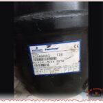
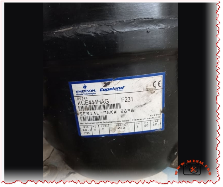
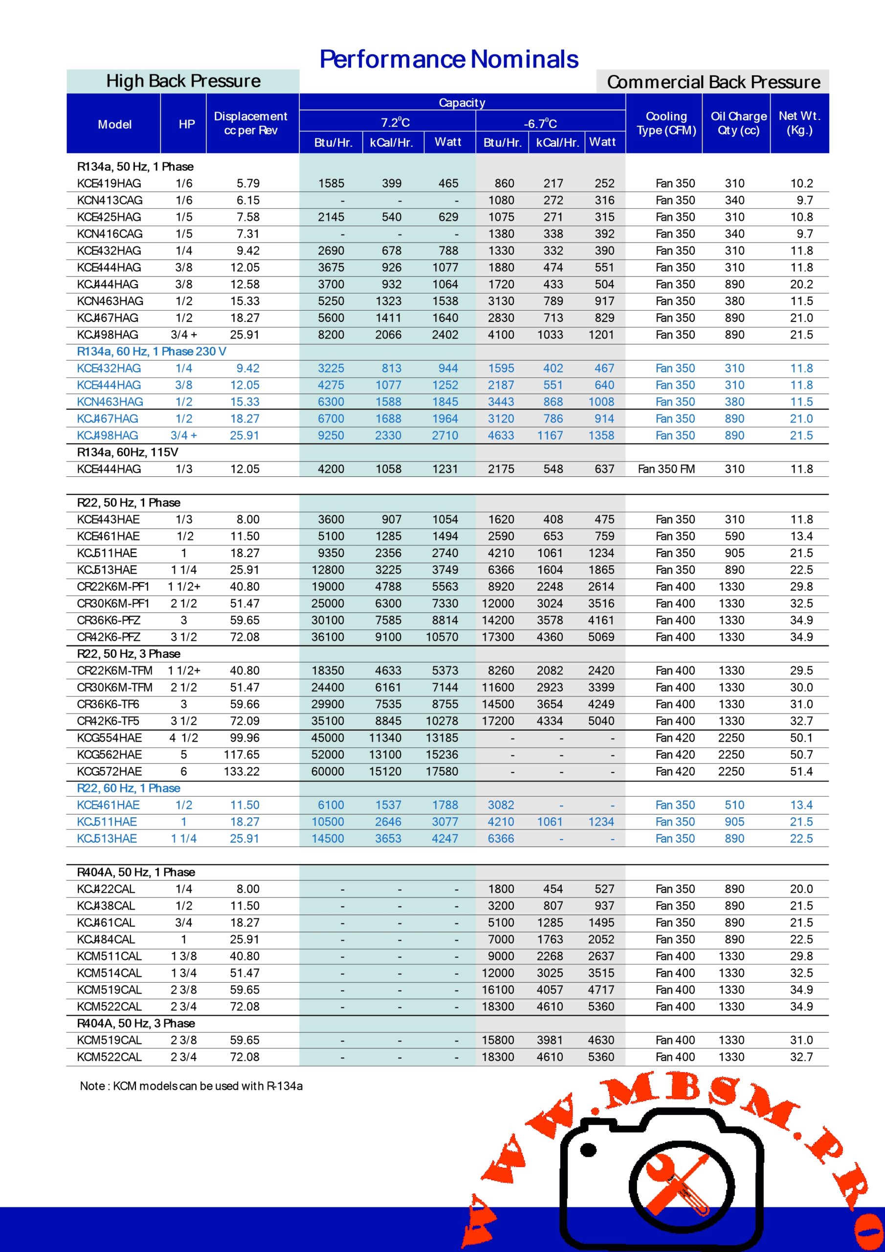
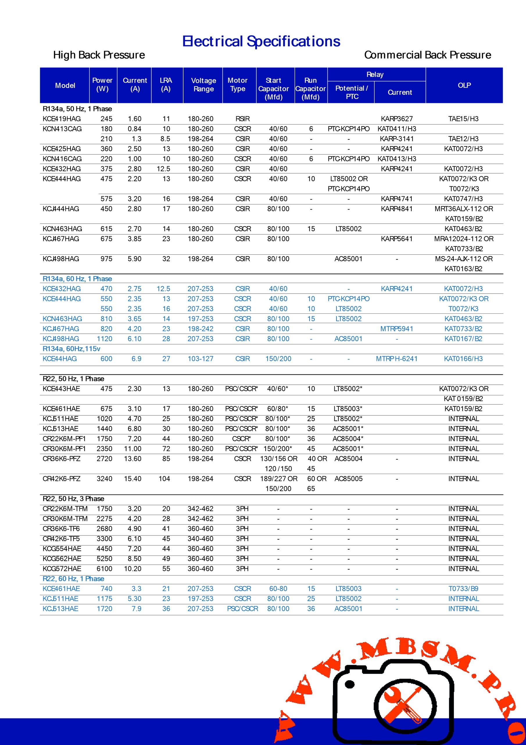
Mbsmpro.com, Compressor, KCE444HAG, 3/8 Hp, Copeland, R134a, 230V 50Hz, High / Medium temperature, Water cooler applications
Overview of the Copeland KCE444HAG compressor
The Copeland KCE444HAG is a hermetic reciprocating compressor designed for high and medium temperature commercial refrigeration using R134a refrigerant. It is widely used in water coolers and bottle coolers where stable performance, compact size, and low noise are required.
Technical specifications and operating range
The KCE444HAG belongs to the KCE family and uses a connecting‑rod type reciprocating mechanism with a single‑phase induction motor. Its evaporating temperature range is approximately −17.8°C to +12.8°C, covering typical high / medium temperature applications in beverage and water cooling.
Main electrical and performance data
Parameter
Value
Notes
Refrigerant
R134a
HFC, medium‑pressure.
Nominal horsepower
0.36 HP (≈3/8 HP)
Depending on rating condition HBP/CBP.
Cooling capacity
1077 W (HBP), 551 W (CBP)
At specified EN12900 conditions.
Power input
475 W (HBP), 339 W (CBP)
Single‑phase operation.
Voltage / frequency
230 V, 50 Hz, 1‑phase
Typical for water coolers 40–80 L.
Motor type
2‑pole single‑phase induction
Internally thermally protected.
Application group
High / Medium temperature (HBP / CBP)
Not suitable for low‑temperature freezing.
Compressor cooling
Fan, about 350 ft³/min
Forced air cooling around shell.
Oil type / volume
POE, approx. 0.31 L
Pre‑charged from factory.
Approx. internal free volume
2400 cm³ (81.1 oz)
Without oil.
This specification table is essential for system designers who must match condenser size, evaporator load, and expansion device selection to the compressor envelope. Using the correct voltage, frequency, and oil type is critical to preserve warranty and avoid early motor or mechanical failure.
Application examples and exploitation in the field
In practice, the KCE444HAG is commonly installed in:
Water coolers between 40 and 80 liter nominal storage.
Bottle coolers and small commercial beverage merchandisers operating in high or medium temperature ranges.
For water coolers, the compressor offers enough capacity to chill drinking water quickly while keeping energy consumption moderate, thanks to its roughly 475 W input at high‑back‑pressure conditions. In bottle coolers, the wide evaporating envelope from negative temperatures up to more than +10°C allows flexible control of cabinet temperature without putting the compressor outside its design limits.
Performance comparison with similar compressors
To understand the real value of the KCE444HAG, it is useful to compare it with another well‑known R134a hermetic compressor such as the GL90AA (ZMC EGL90AA) widely used in domestic and light commercial refrigeration.
Capacity and power comparison
Model
Refrigerant
Nominal HP
Cooling capacity (approx.)
Input power
Typical use
KCE444HAG
R134a
0.36 HP
1077 W (HBP), 551 W (CBP)
475 W (HBP)
Commercial water/bottle coolers.
EGL90AA (GL90AA)
R134a
0.25 HP
227 W (LBP)
–
Domestic refrigerators, small LBP cabinets.
From this table, the KCE444HAG clearly delivers a much higher cooling capacity than the EGL90AA, which translates into faster pull‑down times and suitability for larger, more demanding systems. However, the smaller EGL90AA consumes less power and is better suited where low‑back‑pressure, small‑load operation is required, such as household fridges and compact freezers.
Application temperature range comparison
Model
Application group
Evaporating temperature range
KCE444HAG
HBP / CBP
−17.8°C to +12.8°C.
EGL90AA
LBP
Around −35°C to −6.7°C in typical LBP charts.
The table shows why the KCE444HAG is chosen for positive temperature applications like water coolers, while the EGL90AA works better in freezer‑type systems requiring lower evaporating temperatures. Selecting the wrong compressor for the required evaporating range can lead to high discharge temperatures, low efficiency, and premature failure.
Installation, reliability, and service considerations
The KCE444HAG compressor must be operated inside the condensing and evaporating temperature envelope defined by the manufacturer to guarantee long service life. The datasheet specifies that performance values are valid only inside this envelope and also gives maximum allowable internal moisture and solid residue limits, emphasizing the need for clean, well‑evacuated systems.
Technicians should:
Use R134a only and charge with the correct POE oil volume if a major repair requires oil replacement.
Keep the mounting angle within the 5° limit and respect guidelines for handling and disposal listed in the detailed product documentation.
Good airflow around the compressor and condenser, combined with properly sized capillary or expansion valve, keeps shell temperature and discharge pressure under control, further improving reliability in continuous water‑cooler duty.
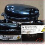
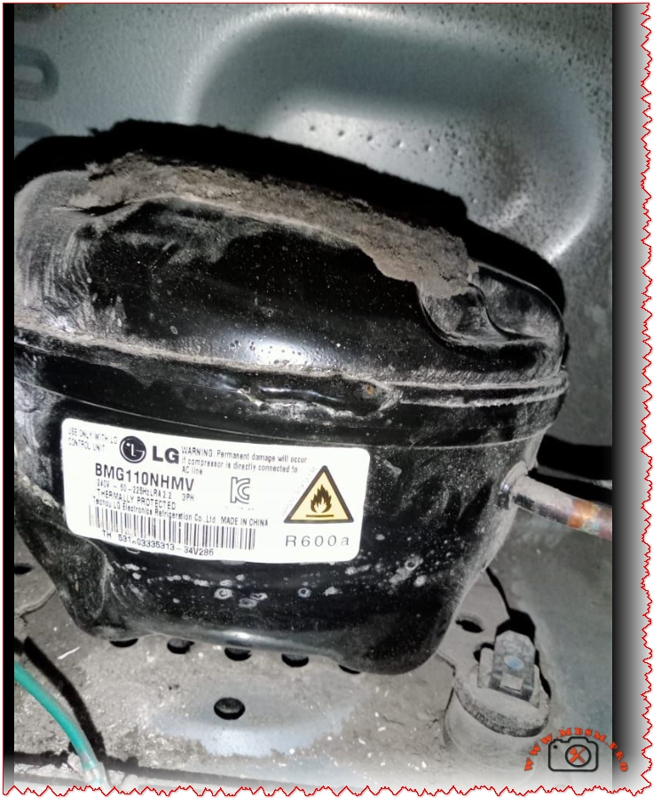
Mbsmpro.com, Compressor, BMG110NHMV, 1/4 hp, LG inverter, Cooling & Freezing, R600a, 220‑240V 50/60Hz, LBP capacity, BLDC, −29°C to −10°C
The LG BMG110NHMV is a variable‑speed BLDC inverter compressor for R600a refrigerators and freezers, working on 220–240 V, 50/60 Hz in low‑back‑pressure applications. With a nominal rating close to 1/4 hp and a speed range from 1200 to 4500 rpm, it delivers flexible capacity and high efficiency for modern domestic appliances.
BMG110NHMV technical profile
LG’s catalog lists the BMG110NHMV in the BMG inverter R600a series, designed for high‑efficiency household refrigerators. The nameplate confirms R600a refrigerant, thermal protection and 220–240 V supply.
At lower speeds like 1500–1800 rpm, capacity drops to around 102–125 W while COP remains near 1.74–1.75, allowing the compressor to modulate for part‑load efficiency.
Capacity table across speeds
The inverter control lets the same compressor cover a wide load range without cycling, which is reflected in LG’s performance table.
Cooling capacity vs power – BMG110NHMV (R600a LBP)
Speed (rpm)
Capacity (kcal/h)
Capacity (W)
Capacity (Btu/h)
Power (W)
COP (W/W)
EER (Btu/W·h)
4500
225
262
894
146
1.79
6.11
3000
172
200
683
108
1.85
6.32
1800
108
125
427
72
1.75
5.97
1500
88
102
349
59
1.74
5.95
1200
70
82
279
48
1.72
5.87
These values show how the inverter platform lets manufacturers tune energy labels by operating much of the time at lower speeds, while still having 262 W on tap for rapid pull‑down.
Comparison with other LG inverter R600a models
LG’s catalog groups the BMG110NHMV with BMG110NAMV and BMG089 series models, all R600a BLDC compressors for LBP applications. Comparing their data helps installers and designers choose the right size.
LG R600a BLDC inverter comparison
Model
Series
Nominal hp class
Capacity at 4500 rpm (W)
Power (W)
COP (W/W)
Typical cabinet volume*
BMG089NAMV
BMG
≈ 3/16 hp
217 W
119 W
1.83
200–260 L refrigerators
BMG089NHMV
BMG
≈ 3/16 hp
217 W
126 W
1.72
high‑efficiency 200–260 L
BMG110NAMV
BMG
1/4 hp class
262 W
144 W
1.82
280–350 L fridges/freezers
BMG110NHMV
BMG
1/4 hp class
262 W
146 W
1.79
280–350 L refrigerators / freezers
*Cabinet volume estimates are typical ranges inferred from inverter R600a design practice, not explicit catalog values.
The BMG110NHMV thus occupies a sweet spot between the smaller BMG089 series and larger BMK/BMA models, ideal for mid‑size no‑frost or multi‑door refrigerators where load fluctuates strongly.
Comparison with fixed‑speed R600a compressors
To highlight the benefit of inverter technology, it is useful to compare BMG110NHMV with a typical constant‑speed R600a compressor of similar hp rating. LG’s own reciprocating catalog and third‑party suppliers show 1/4 hp fixed‑speed R600a models with similar cooling capacity but higher average power consumption.
Inverter vs fixed‑speed R600a – indicative comparison
Feature
BMG110NHMV (inverter)
Typical 1/4 hp fixed‑speed R600a compressor
Speed control
1200–4500 rpm via BLDC inverter
Single speed (≈ 3000 rpm)
Nominal capacity
≈ 262 W at −23.3 °C
≈ 250–270 W at similar point
Input power
146 W at full speed, 48–108 W at reduced speed
≈ 180–200 W constant
COP / EER
Up to ≈ 1.85 W/W (6.3 Btu/W·h)
Typically 1.5–1.6 W/W (5.1–5.5 Btu/W·h)
Temperature control
Smooth, low‑noise modulation
On/off cycling, higher noise and temperature swing
Energy label impact
Enables A+/A++ energy classes in many markets
Usually lower efficiency class
This comparison explains why OEMs increasingly specify BMG‑series compressors in premium, energy‑efficient refrigerators.
Safety and application notes for R600a systems
Because BMG110NHMV uses R600a, a flammable hydrocarbon, system design and service procedures must follow IEC and manufacturer guidelines.
Charge quantities in household refrigerators are limited, typically below 150 g, to remain within safety limits.
Electrical components near the compressor must be sealed or spark‑free, and any repair involving brazing requires full refrigerant recovery and ventilation.
These constraints do not reduce performance; they simply require disciplined handling, especially when replacing the compressor or modifying pipework.
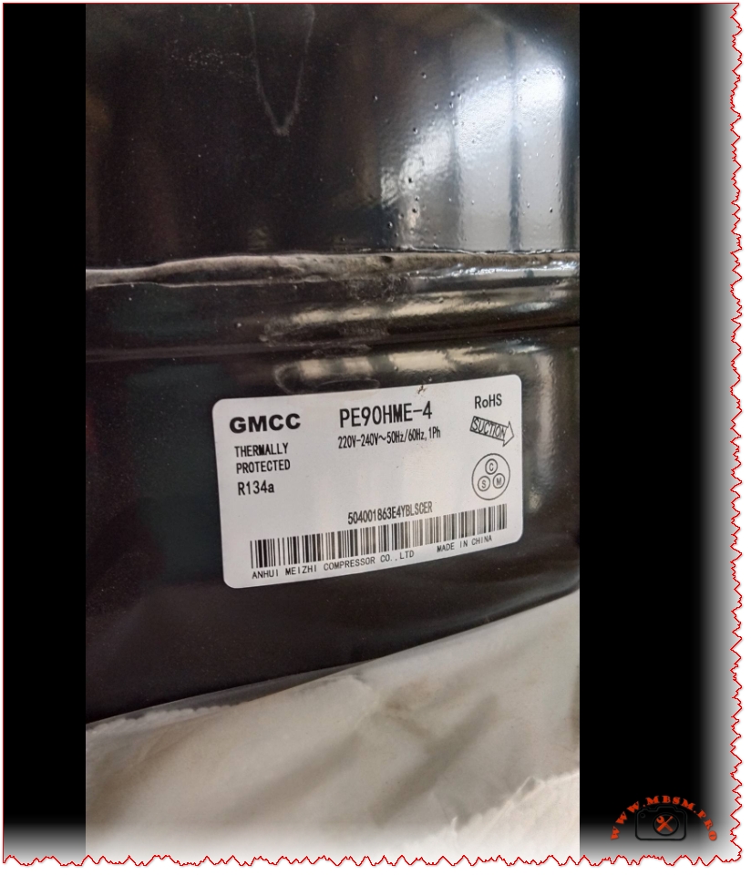
Mbsmpro.com, Compressor, PE90HME‑4, 1/3 hp class, GMCC, Cooling, R134a, 265–295 W, 1.55 A, 1Ph 220‑240V 50/60Hz, LBP capacity, RSCR motor, −23.3°C to −10°C
The GMCC PE90HME‑4 is a hermetic reciprocating refrigerator compressor optimized for R134a and low‑back‑pressure applications at 220–240 V, 50/60 Hz. With a displacement of about 9.0 cm³ and catalog cooling capacities between 265 and 295 W around freezer conditions, it sits in the 1/3 hp performance class and targets domestic and light commercial refrigerators.
GMCC PE90HME‑4 technical identity
The label identifies the compressor as thermally protected, RoHS‑compliant and designed for R134a static‑cooling appliances. It belongs to the PE series of GMCC light commercial units produced by Anhui Meizhi Compressor Co., Ltd.
Nameplate and catalog data
Item
Value / description
Brand
GMCC – Anhui Meizhi Compressor Co., Ltd.
Model
PE90HME‑4
Refrigerant
R134a, low‑back‑pressure (LBP) range
Voltage / frequency
220–240 V, 50/60 Hz, single‑phase (1Ph)
Motor type
RSCR (resistance start, capacitor run)
Displacement
≈ 9.0 cm³
Cooling capacity
265–295 W at LBP conditions (−23.3 °C evap, 32.2 °C amb.)
Input power
≈ 1.52–1.55 A rated current at 220–240 V
Application
Static‑cooling domestic and small commercial refrigerators, freezers and coolers
The RSCR motor concept means a start capacitor is used only during start while a smaller run capacitor remains in circuit, balancing starting torque, efficiency and cost for fractional‑horsepower refrigeration.
Operating envelope and performance
GMCC’s reference data for the PE90H1F‑4 and PE90HME‑4 show nearly identical working limits, giving a clear view of the envelope in which this compressor is expected to operate. These limits are critical for system designers who must match capillary length, condenser size and evaporating temperature.
Operating limits
Parameter
Typical PE90HME‑4 values
Evaporating temperature range
−35 °C to −10 °C (LBP)
Nominal rating point
−23.3 °C evap / 32.2 °C ambient / 55 °C condensing
Voltage range
187–254 V (50 Hz)
Ambient temperature range
0–43 °C
Max condensing temperature
60–70 °C
Max discharge gas temperature
130 °C
Max winding temperature
130 °C (internal)
Max pump‑down pressure
≈ 1.82 MPa
At the nominal point the compressor typically delivers around 265 W at 1.55 A, while higher ambient or less negative evaporating temperatures move capacity closer to 295 W but also increase power input. GMCC specifies vibration levels below 4.9 m/s² and sound levels compatible with household refrigerator noise expectations.
Comparison with other GMCC R134a PE series models
To position the PE90HME‑4 correctly for selection and replacement, it helps to compare it with nearby models such as PE65H1H‑9 and PE90H1F‑9 from the same GMCC R134a range.
GMCC R134a LBP models – performance comparison
Model
Displacement (cm³)
Cooling capacity at 50 Hz (W)*
HP class
Rated current (A)
Application
PE65H1H‑9
6.5
190–195 W
1/4 hp
≈ 1.47–1.55
LBP domestic refrigerators
PE90HME‑4
9.0
265–295 W
1/3 hp class
≈ 1.52–1.55
LBP refrigerators / freezers
PE90H1F‑9
9.0
275–280 W
1/3 hp+
≈ 1.50
LBP with wide‑voltage range
PE120HMH★
12.0
320 W
3/8–1/2 hp
≈ 1.45
L/MBP commercial coolers
*Capacity values taken at −23.3 °C evap / 32 °C amb., minor differences by catalog edition.
Compared with the PE65H1H‑9, the PE90HME‑4 delivers roughly 40–50% more capacity at similar current, making it better suited to 280–400 L refrigerators or small freezers that need stronger pull‑down. Against the PE90H1F‑9, performance is very close; differences are mainly in voltage tolerance (wide‑range versions) and detailed application approvals rather than raw capacity.
Practical applications and selection tips
Designers and technicians usually choose the GMCC PE90HME‑4 when they need a robust, mid‑size R134a compressor that balances capacity, energy efficiency and cost. It is especially attractive in markets where 220–240 V 50 Hz is standard and where appliances are exposed to high ambient temperatures.
Typical uses
Static‑cooling household refrigerators in the 300–400 L range.
Upright or chest freezers requiring −23 °C design evaporating temperature.
Commercial beverage coolers and display cases using R134a and capillary expansion.
Selection and replacement considerations
Checkpoint
Why it matters
Refrigerant
Must be R134a; conversion from R12 or R600a requires full system redesign.
Evaporating temperature
Ensure design conditions fall inside −35 to −10 °C LBP range.
Condenser and capillary sizing
Match to 265–295 W capacity to avoid flood‑back or high‑head faults.
Voltage stability
Mains should remain within 187–254 V; more unstable grids may justify wide‑voltage models like PE90H1F‑9.
Start components
RSCR start kit (PTC + capacitor) must match GMCC’s specified values to guarantee torque and reliability.
Mbsmpro.com, Compressor, CSR terminals, Common Start Run, PTC relay, overload, start and run capacitor wiring, PSC CSIR CSR motors, multimeter ohm testing
Compressor Windings, CSR Terminals, and Start Devices: Practical Guide for Technicians
Single‑phase hermetic compressors use three terminals – Common (C), Start (S), and Run (R) – and a combination of overload, relay, and capacitor to start and run safely. Correctly interpreting CSR pin configuration and wiring the starting devices is critical for reliable refrigeration service work and for avoiding repeated compressor burn‑outs.
Understanding C, S, and R terminals
On most refrigeration compressors, the three pins form either a triangle or a straight line, and each pin connects to one or both motor windings inside the shell. When the original diagram is missing, technicians can still identify each terminal by measuring resistance with a digital multimeter.
Typical resistance relationships
Measurement pair
Identification rule
Typical range*
C–R
Run winding (lowest resistance)
About 1–5 Ω on small fractional‑HP units.
C–S
Start winding (medium resistance)
Usually 3–11 Ω, often 3–5 times C–R.
S–R
Start + run (highest resistance)
Equals C–S + C–R by ohm’s law.
*Values vary by model; always compare with the manufacturer’s data sheet when available.
To confirm readings, many trainers recommend writing each resistance value on a sketch of the pin layout and checking that the highest reading equals the sum of the other two. If the numbers do not add up, the compressor may have an open winding or internal damage.
CSR, RSIR, CSIR and PSC motor concepts
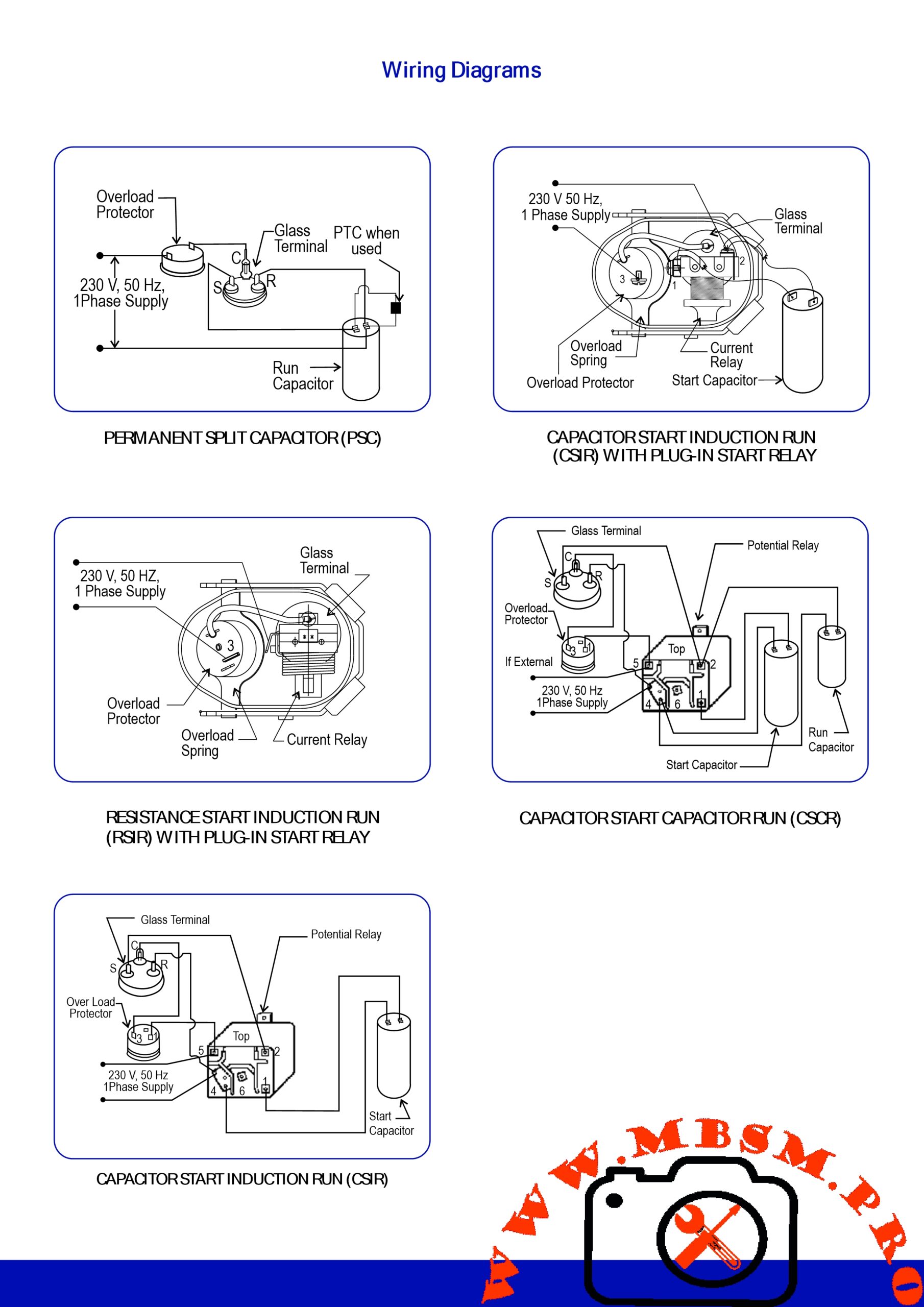
Single‑phase hermetic motors are classified by how capacitors and relays are used with start and run windings. The most common arrangements in light commercial refrigeration are RSIR, PSC, CSIR and CSR, each with different starting torque and component requirements.
Motor types and starting characteristics
Motor type
Components
Typical use case
Starting torque
RSIR (Resistance Start Induction Run)
Start relay + start winding, no capacitor
Small domestic refrigerators, low starting torque.
Low
PSC (Permanent Split Capacitor)
Run capacitor in series with start winding
Smooth, efficient operation, good for low starting load.
Low–medium
CSIR (Capacitor Start Induction Run)
Start capacitor + relay, start winding only during start
Higher torque for larger compressors up to ≈ 3/4 HP.
High
CSR (Capacitor Start Capacitor Run)
Start capacitor + run capacitor + potential or current relay
Very high starting torque for hard‑start conditions.
Very high
CSR systems keep a smaller run capacitor in the circuit after startup to improve power factor and running efficiency while the start capacitor is removed by the relay. These motors are common in high‑starting‑torque (HST) versions of commercial compressors where frequent cycling and high condensing pressures are expected.
Overload, PTC relay, and run capacitor wiring
The start device assembly brings together three safety‑critical components: thermal overload, relay (or PTC), and capacitor. Correct wiring ensures that line voltage reaches the run winding continuously, energizes the start winding only during startup, and disconnects the compressor when overcurrent or overheating occurs.
Typical PTC / solid‑state relay and overload wiring (120–240 V)
Step
Connection
Function
1
Line (L) feeds the overload protector, which then connects to C
Overload opens on excessive current or shell temperature.
2
Solid‑state relay/PTC connects between C and S with start capacitor in series if CSIR/CSR
Provides high initial current to start winding, then increases resistance and drops out.
3
Line (L) also connects directly to R through the control circuit (thermostat, contactor)
Supplies continuous voltage to run winding during operation.
4
Run capacitor connects between S and R in PSC and CSR systems
Improves running efficiency and torque.
Before wiring, technicians should verify that the overload has less than 1 Ω resistance when cold and that the relay coil or PTC element shows the manufacturer’s specified resistance range. Any signs of arcing, discoloration or cracked housings are reasons to replace the start device rather than re‑use it.
Multimeter checks and safety best practices
Accurate ohm measurements and ground tests are indispensable when diagnosing compressor failures or confirming correct CSR identification. At the same time, technicians must follow lock‑out/tag‑out procedures and respect the refrigeration system’s pressure hazards.
Recommended testing workflow
Isolate and discharge
Disconnect power, verify zero voltage, and discharge capacitors before touching any terminals.
Ohm the windings
Measure all three combinations (C–R, C–S, S–R), verify the add‑up rule, and compare with catalog ohm ranges when available.
Check for shorts to ground
Use the highest megohm setting to test between each terminal and the shell; any measurable continuity usually means the compressor is grounded and must be replaced.
Verify start components
Measure overload resistance (<1 Ω closed) and relay / PTC resistance (3–26 Ω typical on many plug‑in designs), and confirm capacitors with a capacitance meter.
Monitor running amperage
After re‑wiring, compare running current with the nameplate RLA or data‑sheet values; high amps may signal improper capacitor size, high head pressure or internal mechanical problems.
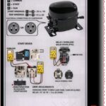
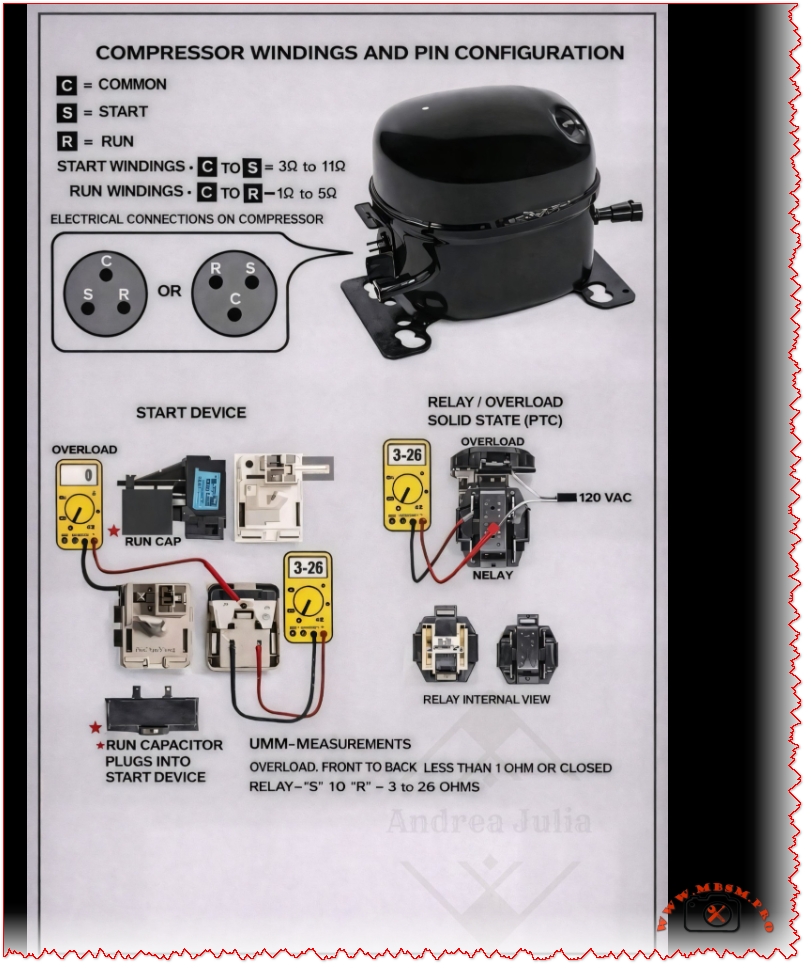
Compressor windings, terminal pin configuration, and the start components used in a refrigerator or air-conditioning compressor.
1. Compressor Windings and Terminals
A single-phase compressor has three terminals: • C (Common) • S (Start) • R (Run) These three pins can be arranged in different physical positions, but their electrical function is the same.
Winding Resistance Values (Typical)
Measured using a multimeter (Ohms Ω): • C to S (Start winding): 3 Ω – 11 Ω • C to R (Run winding): 1 Ω – 5 Ω • S to R = Start + Run (highest resistance) The Start winding always has higher resistance than the Run winding.
2. Electrical Connection on the Compressor
The diagram shows two possible layouts of the compressor pins. Even if the position changes, the labels C, S, and R must be identified correctly before wiring.
3. Start Device Assembly
The start system usually consists of: • PTC Relay (Solid State Relay) • Overload Protector • Run Capacitor (if used)
Functions: • PTC Relay: – Temporarily connects the Start winding during startup. – Disconnects it automatically once the compressor is running.
• Overload Protector: – Protects the compressor from overheating or overcurrent. – Opens the circuit if temperature or current is too high.
• Run Capacitor (optional on some models): – Improves efficiency and torque during operation.
4. Multimeter Testing (Shown in Image)
Overload Test: • Measure front to back • Reading should be less than 1 Ω (closed circuit)
Relay Test: • Measure between S and R • Normal reading: 3 Ω – 26 Ω
Abnormal readings indicate a faulty relay or overload.
5. Power Supply • The diagram shows 120 VAC input going through: – Overload → Relay → Compressor terminals
6. Internal Relay View
The bottom-right images show the internal structure of the relay, helping identify contacts and working condition.
See less
Danfoss FR10B 103U2954 Compressor
Category: Refrigeration
written by www.mbsmpro.com | December 31, 2025
Danfoss FR10B 103U2954 Compressor: Technical Identification, Application Range, and Performance Data
Most references that detail this model (FR10B, code 103U2954) explicitly describe it as a “FR10B HST 1/4 HP” or note power range information confirming the quarter‑horsepower classification.
The Danfoss FR10B with code 103U2954 is a light commercial hermetic reciprocating compressor designed for low‑back‑pressure refrigeration on 220–240 V, 50/60 Hz power supplies. It is widely used in commercial refrigerators and freezers and is part of the Danfoss/SECOP FR series known for compact design and reliable operation in R12 and later R134a applications.
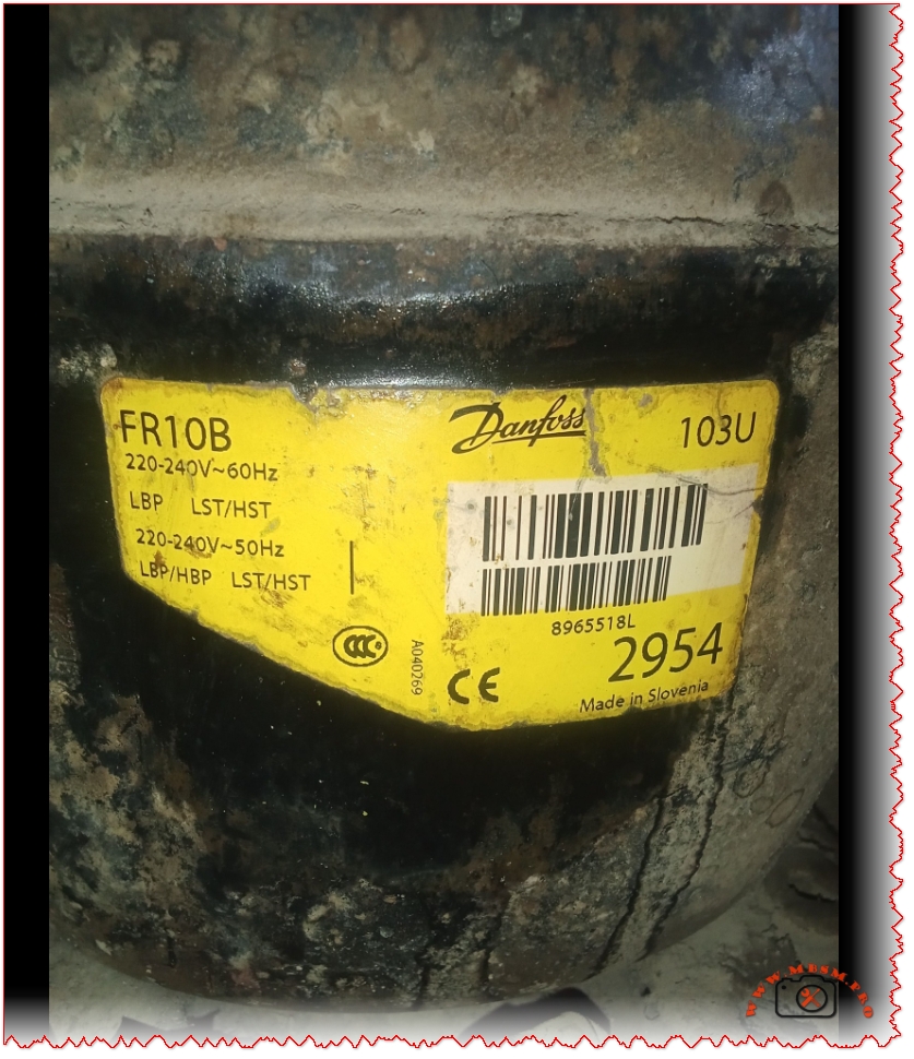
Nameplate decoding: FR10B 103U2954
The yellow identification label on this compressor summarizes its key application and electrical data in a compact format. Understanding every line of that label is essential for correct replacement, troubleshooting, or system redesign.
Part of light commercial range for small refrigeration units.
103U2954
Complete compressor code number
Identifies factory configuration, oil charge and terminal box.
220–240 V ~ 60 Hz / 50 Hz
Dual‑frequency single‑phase motor
Designed for 220–240 V at either 50 or 60 Hz mains.
LBP / LBP‑HBP
Low‑back‑pressure and some high‑back‑pressure use
Suited to freezers (LBP) and certain refrigerator duties (HBP) depending on model variant.
LST / HST motor
Low / high starting torque versions
CSIR or RSIR motor concepts, depending on accessory set and application.
Made in Slovenia
Manufacturing plant
Danfoss/SECOP European production facility.
Technical specifications and operating envelope
The FR10 family has been documented in several universal catalogs, which provide detailed operating conditions for R12 and later R134a refrigerants. The FR10B 103U2954 follows the same mechanical platform and performance class as the FR10G universal compressor.
Main technical data (FR10 series, R134a/R12 class)
Parameter
Typical value / range
Source indication
Refrigerant
R12 on legacy 103U2954 versions; R134a on FR10G successors
Application
LBP (freezers −30 °C to −10 °C evap); some HBP/MBP possible
Displacement
≈ 9.05 cm³
FR10G catalog data.
Voltage range
187–254 V at 50 Hz for LBP
Max ambient temperature
43 °C
Max condensing temperature
60–70 °C continuous/short
Motor type
RSIR/CSIR single‑phase
Oil type / charge
Polyolester or mineral, ≈ 450 cm³ depending on refrigerant
Max refrigerant charge
≈ 900 g
Weight
Around 10–11 kg
Performance snapshot at typical freezer conditions
Condition
Capacity (approx.)
Power input
Notes
Evap −25 °C, cond 55 °C, 220 V / 50 Hz
~130–150 W refrigerating
~200–230 W
FR10G LBP data as reference for FR10B.
Evap −15 °C, cond 55 °C
Higher capacity around 200 W
Increased input and COP
Suited for high‑efficiency bottle coolers.
These figures are indicative and should always be cross‑checked with the exact data sheet for the specific refrigerant and code number when designing or verifying a system.
Application in commercial refrigeration
The FR10B 103U2954 compressor is typically installed in small commercial cold rooms, display freezers, under‑counter cabinets and chest freezers where compact dimensions and dependable low‑temperature performance are critical. Its evaporating temperature range down to about −30 °C makes it suitable for frozen food storage and ice‑cream applications.
Typical systems using FR10B
Glass‑door upright freezers in supermarkets and convenience stores.
Compact chest freezers and island cabinets for frozen food.
Under‑counter commercial refrigerators where LBP/HBP dual range is required.
Advantages for installers and OEMs
Advantage
Description
Proven reliability
Long‑running Danfoss/SECOP FR platform with global service support.
Wide voltage tolerance
Operates from 187–254 V, useful in markets with unstable mains.
Flexible application
LBP primary, with variants for HBP duties using alternative starting devices.
Compact footprint
Fits tight condensing unit housings and under‑counter cabinets.
Service notes, replacement options and energy considerations
Over time, FR10B compressors in the field often need replacement because of mechanical wear, electrical failures or refrigerant conversion projects. When selecting a replacement, technicians frequently upgrade to modern FR10G or FR10GX R134a versions that offer similar footprint but better efficiency and environmental performance.
Replacement and retrofit guidance
Match application range and refrigerant
For original R12 systems, many retrofit projects convert to R134a with corresponding FR10G/FR10GX models, observing manufacturer guidelines for oil type and charge.
System components such as capillary tubes and filters must be recalculated for the new refrigerant to maintain correct superheat and capacity.
Preserve electrical compatibility
Ensure that the new compressor operates on 220–240 V, 50/60 Hz and that starting devices (PTC, relay, capacitor) match the recommended CSIR/RSIR configuration.
Check locked‑rotor current and recommended fuse size to avoid nuisance tripping on older installations.
Optimize energy efficiency
Danfoss high‑efficiency light commercial compressors can cut appliance energy consumption by 10–30% compared with older standard models, which is especially relevant in 24/7 commercial refrigeration.
When installing a replacement, technicians should verify condenser cleanliness, airflow, and thermostat settings to fully benefit from improved compressor performance.
Fresh SFW13C1P-B Split Air Conditioner: Technical Label, Specifications, and Error 11.1 Guide
The Fresh SFW13C1P-B split air conditioner is a 1.5 HP cooling‑only indoor unit designed for 220–240 V residential applications, with a cooling capacity around 12,000 BTU/h and R22 refrigerant. Its nameplate also references the diagnostic code ERR 11.1, which technicians commonly associate with serial communication faults between indoor and outdoor units on similar split systems.
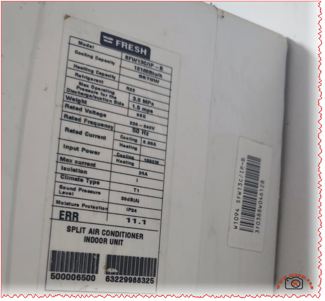
Nameplate data overview
The identification label on the Fresh SFW13C1P-B indoor unit groups the key electrical and operating data needed for installation, commissioning, and service.
Model family: SFW13C series, 1.5 HP, cooling‑only split air conditioner.
Typical application: Small to medium rooms (about 12–18 m² depending on climate and insulation).
Refrigerant: R22 on legacy units in this series, with specified maximum operating pressures for high and low sides.
Fresh SFW13C1P-B basic specifications
Parameter
Typical value / range
Notes
Series / model
SFW13C / SFW13C1P-B
Smart digital wall‑mounted split.
Type
Split air conditioner, indoor unit
Wall hi‑wall design.
Nominal horsepower
1.5 HP
Residential/light‑commercial class.
Cooling capacity
≈ 12,000 BTU/h
Catalog values for 1.5 HP Fresh SFW13C.
Function
Cooling only
No heat pump on this variant.
Refrigerant
R22
On older SFW13C inverter range.
Voltage
220–240 V
Single‑phase supply.
Frequency
50 Hz
MEA / Africa grid standard.
Moisture protection
IP24 (indoor casing)
Splash‑resistant enclosure category on label.
Sound pressure level
≈ 39 dB(A) indoor
Quiet residential operation.
Electrical and operating characteristics
The label on the SFW13C1P‑B provides detailed electrical data that help installers size breakers, cables, and protection devices correctly.
Rated voltage 220–240 V, 50 Hz single‑phase with electronic inverter control on associated outdoor units in the SIFW/SFW families.
Rated and maximum currents are specified (often around 6–8 A running and 20–25 A max), guiding breaker choice and cable sizing.
Input power on cooling is in the 1.5 kW class for a 1.5 HP Fresh split, which matches catalog data for SIFW13C‑IP and SFW13C series.
Indicative electrical table for 1.5 HP Fresh SFW13C series
Item
Typical value
Practical implication
Rated current (cooling)
≈ 6–7 A
Used to check running load.
Maximum current
≈ 25 A
Used for MCB / fuse rating margin.
Rated input power
≈ 1,560 W
Helps estimate energy consumption.
Isolation / protection
25 A marking, IP24
Indoor unit protection coordination.
ERR 11.1 on Fresh SFW13C1P-B
The nameplate of this indoor unit explicitly lists “ERR 11.1”, indicating that self‑diagnostic communication is part of the design.
On many inverter split systems, error 11 or 11.1 corresponds to a serial communication error between indoor and outdoor units (loss or corruption of signal on the interconnecting terminals).
Service manuals for comparable brands describe error 11 as forward or reverse transfer serial communication failure, often triggered when the outdoor PCB does not properly receive the indoor control signal for 10 seconds or more.
Typical causes associated with error 11 / 11.1
Possible cause
Description
Reference behavior
Loose or oxidized interconnecting terminals
Poor contact on indoor–outdoor signal cable can interrupt data communication.
Wrong wiring sequence
Reversed communication cores (e.g., terminals 2–3 swapped) lead to serial transfer errors.
Damaged communication cable
Mechanical damage or moisture ingress causes intermittent signal loss.
PCB failure
Indoor or outdoor main board cannot generate or read serial signal.
External electrical noise
Strong interference, bad earthing or voltage dips disturb the serial bus.
Professional troubleshooting approach
Professional technicians treating a Fresh SFW13C1P‑B that displays ERR 11.1 can follow a methodical process inspired by standard inverter AC service instructions.
Reset and verify supply
Isolate power for several minutes, then re‑energize and confirm that error 11.1 reappears under normal load, ruling out a temporary voltage dip.
Check mains voltage within 220–240 V and verify correct earthing to reduce electrical noise on the serial line.
Inspect communication wiring
Confirm that the communication terminals on indoor and outdoor units are tightened, corrosion‑free, and wired in the manufacturer’s order.
Trace the cable path for cuts, joints, or water ingress, replacing suspect lengths with shielded cable where specified.
Measure serial signal
Service documentation for similar systems specifies that the AC serial signal between designated terminals should swing within an expected voltage window (for example, 30–130 V AC) during operation; abnormal readings indicate PCB or wiring faults.
During measurement, verify that fan motors and relays do not induce excessive noise on the same harness.
Evaluate PCBs and external causes
When wiring and supply are correct, error 11.1 persisting usually points to indoor or outdoor controller PCB failure.
Before replacing boards, technicians should rule out external causes such as unstable power feeders, undersized generators, or nearby heavy electrical machinery.
User‑oriented best practices
End users operating a Fresh SFW13C1P‑B split unit can reduce the risk of error codes and extend system life by following a few simple best practices derived from documentation of modern Fresh air conditioners.
Maintain clean indoor filters to preserve airflow and reduce strain on the refrigeration circuit and electronics.
Avoid repeatedly cycling power from the main breaker, as frequent restarts stress inverter components and communication circuits; instead use the remote control for routine on–off operations.
If error 11.1 appears repeatedly after a full power reset, contact qualified HVAC service instead of attempting to rewire the communication cable.
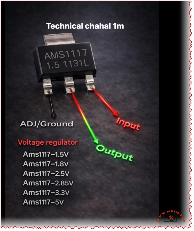
AMS1117 Voltage Regulator Pinout and Versions: Complete Guide for Electronics Projects
The AMS1117 family is one of the most widely used linear regulators for stepping down DC voltages in embedded and DIY electronics projects. Its simple three‑pin layout and multiple fixed output versions make it an excellent choice for powering microcontrollers, sensors, and communication modules.
AMS1117 overview
The AMS1117 is a low‑dropout (LDO) linear voltage regulator capable of delivering up to 1 A of continuous current, depending on heat dissipation and PCB design.
It is available as fixed‑output regulators (1.5 V, 1.8 V, 2.5 V, 2.85 V, 3.3 V, 5 V and others) and as an adjustable version that can be set from about 1.25 V to 12 V using external resistors.
Pinout: input, output, and ground/ADJ
In the common SOT‑223 package, the pins from left to right (front view, text facing you) are ADJ/GND, OUTPUT, and INPUT.
For fixed versions (such as AMS1117‑3.3 or AMS1117‑5.0), the first pin is tied to ground, while for the adjustable version it is used as the ADJ pin to set the output voltage with a resistor divider.
Fixed output AMS1117 variants
The table below summarizes popular fixed‑voltage versions and typical use cases.
AMS1117 version
Nominal output
Typical application example
AMS1117‑1.5
1.5 V
Low‑voltage ASICs, reference rails
AMS1117‑1.8
1.8 V
ARM cores, SDRAM, logic ICs
AMS1117‑2.5
2.5 V
Older logic families, ADC/DAC rails
AMS1117‑2.85
2.85 V
Mobile RF, modem chipsets
AMS1117‑3.3
3.3 V
MCUs, sensors, 3.3 V logic from 5 V sources
AMS1117‑5.0
5.0 V
Regulating from 7–12 V to 5 V logic or USB lines
Electrical characteristics and design tips
The typical input range for AMS1117 regulators is up to 12–15 V, with a dropout voltage around 1.1–1.3 V at 1 A, meaning the input must be at least about 1.3 V higher than the desired output.
For stable operation, manufacturers recommend small bypass capacitors at both input and output (for example 10 µF electrolytic or tantalum), which help reduce noise and improve transient response in digital circuits.
Typical applications in embedded systems
AMS1117 regulators are frequently used to derive 3.3 V from 5 V USB or 9–12 V adapter inputs in Arduino‑style development boards and sensor modules.
Thanks to built‑in thermal shutdown and short‑circuit protection in many implementations, these regulators offer a robust solution for compact PCBs, IoT nodes, and hobby electronics where space and simplicity are critical.