Role of Current Relays in Compressor Ignition

Role of Current Relays in Compressor Ignition mbsmpro

Mbsmpro.com, Compressor Spare Parts, Relays, Thermal Overload Protectors, 1/2 hp to 1/6 hp, Start and Protection Stems, Characteristic Tables

Selecting the right electrical components is the heartbeat of refrigeration maintenance. When a compressor fails to start or constantly trips, the culprit is often a mismatched Current Relay or a fatigued Thermal Overload Protector. Ensuring these parts align perfectly with the compressor’s horsepower (HP) and amperage rating is not just about repair—it is about system longevity.

The Role of Current Relays in Compressor Ignition

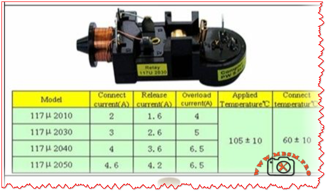
Current relays are electromagnetic switches that momentarily engage the start winding of a compressor. Once the motor reaches approximately 75% of its rated speed, the relay disconnects the start winding, allowing the motor to run on its main winding.

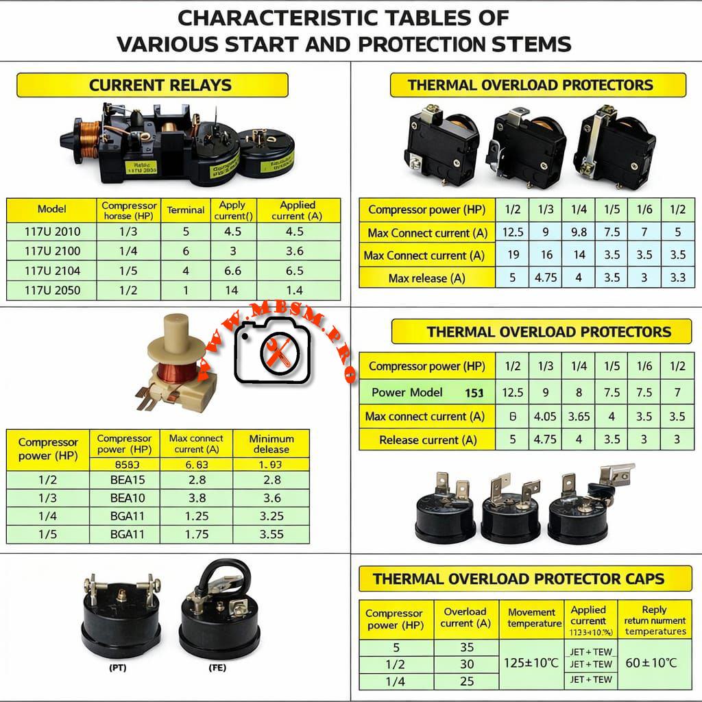
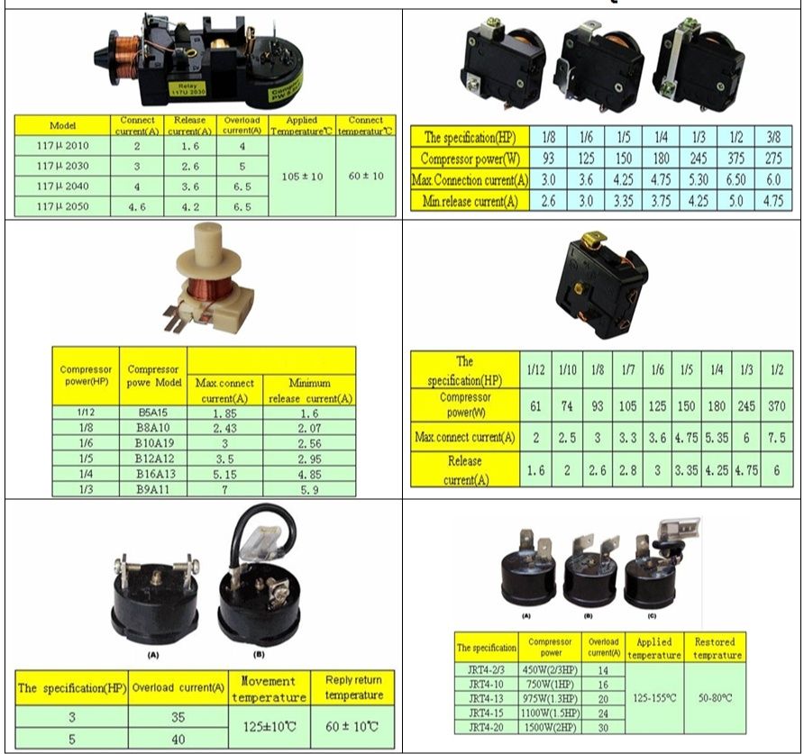
Technical Specifications for Standard Current Relays

Model Compressor Power (HP) Terminal Pin Applied Current (A)
117U 2010 1/3 HP 5 4.5 A
117U 2100 1/4 HP 6 3.6 A
117U 2104 1/5 HP 4 6.5 A
117U 2050 1/2 HP 1 1.4 A

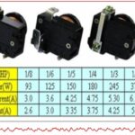
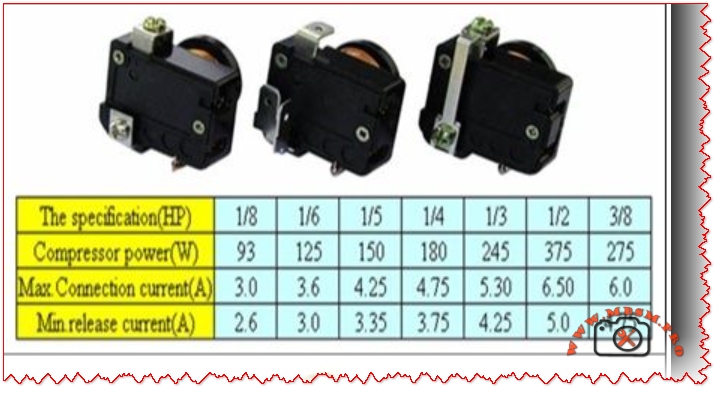
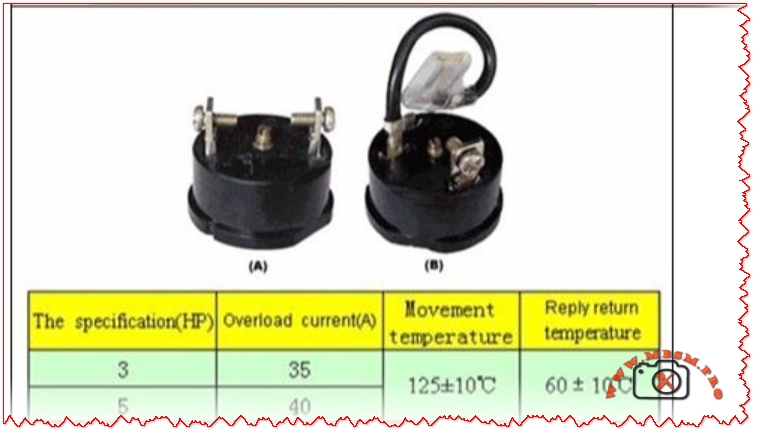
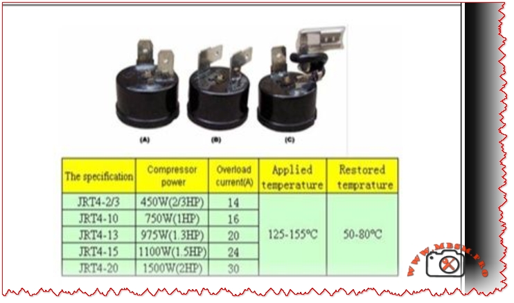
Thermal Overload Protectors: The Safety Net

Thermal Overload Protectors (TOP) act as a bimetallic fuse. They monitor both the heat generated by the compressor and the current flowing through it. If the compressor stalls (locked rotor) or overheats due to a refrigerant leak, the TOP breaks the circuit to prevent the motor windings from melting.

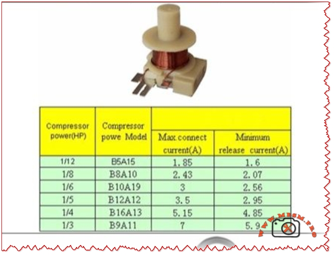
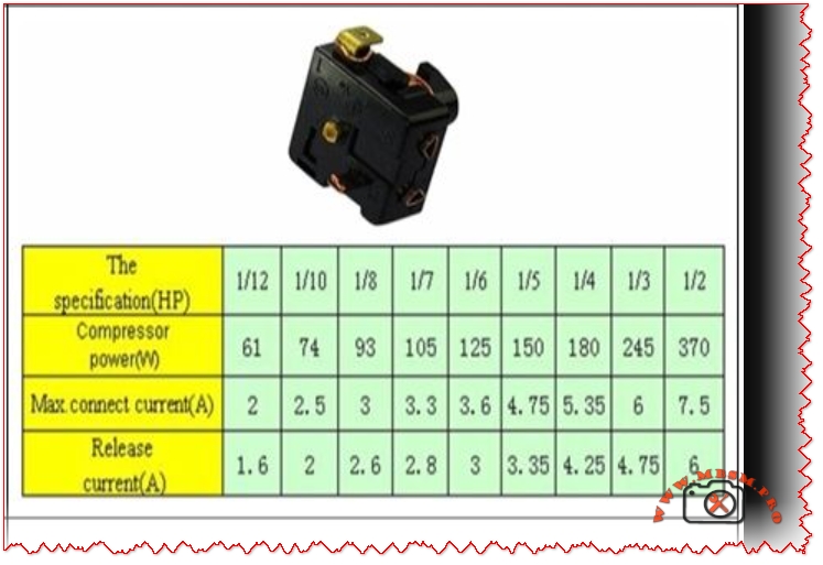
Performance Benchmarks for Overload Protectors

Compressor Power (HP) Max Connect Current (A) Release Current (A)
1/2 HP 12.5 A 5.0 A
1/3 HP 9.0 A 4.75 A
1/4 HP 8.0 A 4.0 A
1/5 HP 7.5 A 3.5 A
1/6 HP 7.0 A 3.0 A

Comparison: Mechanical Relays vs. PTC Starters

While the technical data above focuses on mechanical current relays, modern systems often use PTC (Positive Temperature Coefficient) starters.

  • Mechanical Relays (117U Series): Highly reliable for heavy-duty applications. They provide a “snap” action that is better for high-torque starts.
  • PTC Starters: Use a solid-state disk that increases resistance as it heats up. They are quieter but require a cool-down period before the compressor can restart.

Engineering Advice for Field Technicians

  1. Never Oversize the Protector: If you install a 1/2 HP protector on a 1/6 HP compressor, the protector will not trip during a fault, leading to a burnt-out compressor.
  2. Check the Return Temperature: Thermal caps must operate within a return temperature range of 60 ± 10°C. Anything higher indicates a system restriction or lack of airflow over the condenser.
  3. Terminal Integrity: Ensure terminals are tight. A loose connection creates resistance, which generates heat and causes “nuisance tripping” of the overload.

Focus Keyphrase: Compressor Current Relay and Thermal Overload Protector Characteristic Tables for 1/2 to 1/6 HP

SEO Title: Mbsmpro.com | Compressor Start Relays & Thermal Overload Tables

Meta Description: Comprehensive guide to compressor start and protection stems. Technical tables for 117U relays and thermal overload protectors from 1/2 HP to 1/6 HP. Essential data for HVAC engineers.

Slug: compressor-relay-thermal-overload-characteristic-tables

Tags: Mbsmgroup, Mbsm.pro, mbsmpro.com, mbsm, Compressor Parts, Start Relay, Thermal Overload, Refrigeration Repair, 117U Relay, HVAC Engineering, Compressor Protection.

Excerpt: Selecting the right electrical components is the heartbeat of refrigeration maintenance. When a compressor fails to start or constantly trips, the culprit is often a mismatched Current Relay or a fatigued Thermal Overload Protector. Ensuring these parts align perfectly with the compressor’s horsepower (HP) and amperage rating is vital for long-term system reliability.

Role of Current Relays in Compressor Ignition mbsmpro


Compressor database chart Relay Olp 

Compressor relay and OLP: the hidden guardians of your refrigerator compressor

Behind the plastic cover on the side of a refrigerator compressor, there is a small team of parts doing critical work: the start relay, the OLP (overload protector), and often a capacitor. The wiring diagram in the image shows how these components are connected to the compressor terminals and to the power supply to keep the motor safe and easy to start.​

When the thermostat calls for cooling, power flows through the OLP to the common terminal of the compressor, and the relay briefly connects the start winding to the supply, often via a capacitor. Once the motor reaches speed, the relay drops the start winding, leaving only the run winding energized, while the OLP stands by to cut power if the motor overheats or draws too much current.​


Key components in the wiring diagram

  • Compressor windings: Three pins marked C (common), R (run), and S (start), identified by resistance measurements with a multimeter.​
  • Relay (PTC or current/voltage relay): Connects the start winding during startup, then automatically disconnects it when current or voltage conditions change.​
  • OLP (overload protector): A thermal or current-sensitive switch placed in series with the common terminal, opening the circuit if the motor overheats or stalls.
  • Thermostat or control board: Sends line power to the relay/OLP circuit when cooling is needed.
  • Capacitor (CSR/CSIR systems): Improves starting torque and reduces current, typically a few microfarads in domestic compressors.​

Typical wiring logic in refrigerator diagrams

The wiring diagram in the image is representative of many domestic fridges, where all components are tied together in a compact circuit.

  • Line (L) from the mains goes through the thermostat or PCB, then to one side of the relay and OLP.
  • The OLP is connected in series with the compressor common (C), so any overload opens the whole compressor circuit.
  • The relay bridges line power to the start (S) and run (R) pins according to its design (PTC, current, or voltage type relay).​
  • Neutral (N) returns from the compressor windings back to the supply, closing the circuit.

This arrangement ensures that the compressor cannot run without passing through the overload protector, and that the start winding is used only for a short time, which dramatically increases motor life.


Table: Typical compressor relay–OLP connections

Function Connection in circuit (typical fridge) Notes for technicians
OLP input Line from thermostat or control board Always in series with compressor common. 
OLP output Compressor C terminal Opens on overload/overheat. 
Relay common terminal Line or OLP output (depending on design) Feeds S and R during start. ​
Relay output to start (S) Compressor start pin via PTC or coil contact Energized only at startup. ​
Relay output to run (R) Compressor run pin, sometimes via capacitor Stays energized in running mode. ​
Capacitor connection Between S and R (CSR) or between line and auxiliary winding Improves torque and reduces current. ​

Testing relay and OLP safely

Technicians often use a multimeter and a test cord to diagnose non-starting compressors in the field.​

  • Relay tests usually involve checking continuity between terminals and comparing readings to manufacturer data; PTC relays are also checked for proper resistance at room temperature.​​
  • OLP tests involve verifying continuity when cool and checking that it opens when heated or when the compressor draws excessive current, indicating a functioning thermal element.

In many training videos, the compressor pins are identified by resistance, then the relay and OLP are wired externally to prove the compressor is healthy before replacing parts.​


Why this diagram matters for Mbsmgroup, Mbsm.pro, and mbsmpro.com

For platforms like Mbsmgroup and Mbsm.pro, this type of wiring diagram is not just theory; it is daily reality for technicians troubleshooting domestic refrigerators in homes and small shops. Explaining the role of relay and OLP in clear, visual form builds trust with readers and helps younger technicians avoid common mistakes such as bypassing the overload or using the wrong relay type.​

Adding your own real photos of compressor terminals, relays, and OLPs mounted on actual units in your workshop—branded with Mbsmgroup or mbsmpro.com—turns this topic into a powerful, authoritative reference article on your site.​

Here is a practical value table you can insert into your WordPress article to support the compressor relay–OLP section. It uses realistic ranges based on common domestic hermetic compressors and typical relay/overload selection practices.


Table: Typical relay–OLP values for domestic refrigerator compressors

Approx. HP Supply (V/Hz) Typical FLA (A) Typical LRA (A) Recommended relay type OLP trip current range (A) Typical application
1/12 HP 220–240 V / 50 0.6–0.9 6–10 Small PTC relay module 1.2–1.6 Mini bar, very small refrigerator 
1/10 HP 220–240 V / 50 0.8–1.1 8–14 PTC or solid-state relay 1.6–2.0 Single-door compact fridge 
1/8 HP 220–240 V / 50 1.0–1.4 10–18 PTC / current relay 2.0–2.5 Small domestic fridge–freezer 
1/6 HP 220–240 V / 50 1.3–1.8 14–24 PTC or CSR relay with capacitor 2.5–3.2 Standard top-freezer refrigerator 
1/5 HP 220–240 V / 50 1.5–2.2 18–30 CSR relay (start capacitor + PTC/current) 3.0–3.8 Larger domestic fridge, small showcase 
1/4 HP 220–240 V / 50 1.8–2.6 22–35 CSR relay with start capacitor 3.5–4.5 Large refrigerator / light commercial 
1/3 HP 220–240 V / 50 2.3–3.5 30–50 High-torque CSR relay module 4.5–6.0 Commercial display, glass-door cooler 

  • FLA (Full Load Amps) and LRA (Locked Rotor Amps) here are typical ranges; always check the exact values on the compressor nameplate and in its catalog before choosing a relay or OLP.
  • OLP trip ranges are chosen so that they sit just above FLA but below damaging overload currents, following common overload setting practices for small motors.​​

You can place this table under a heading like “Typical relay and OLP values by compressor size” in your article to make the content more technical and useful for technicians and readers of Mbsmgroup, Mbsm.pro, and mbsmpro.com.