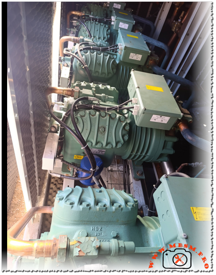
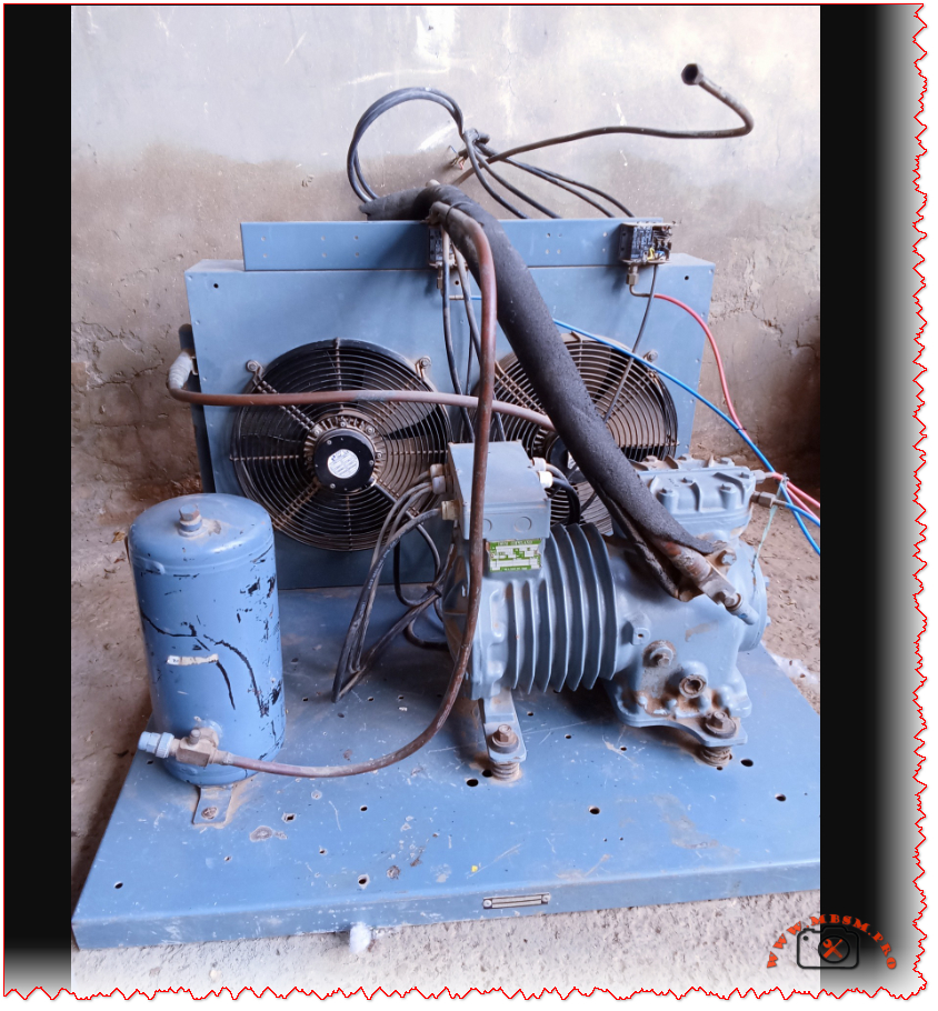
Bitzer 4J-13.2Y-40P semi-hermetic
Bitzer 4J‑13.2Y‑40P Compressor: How to Read and Use the Nameplate Data
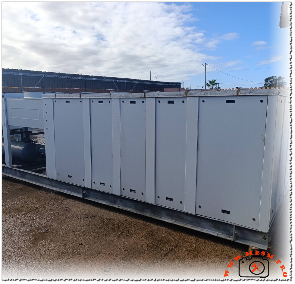
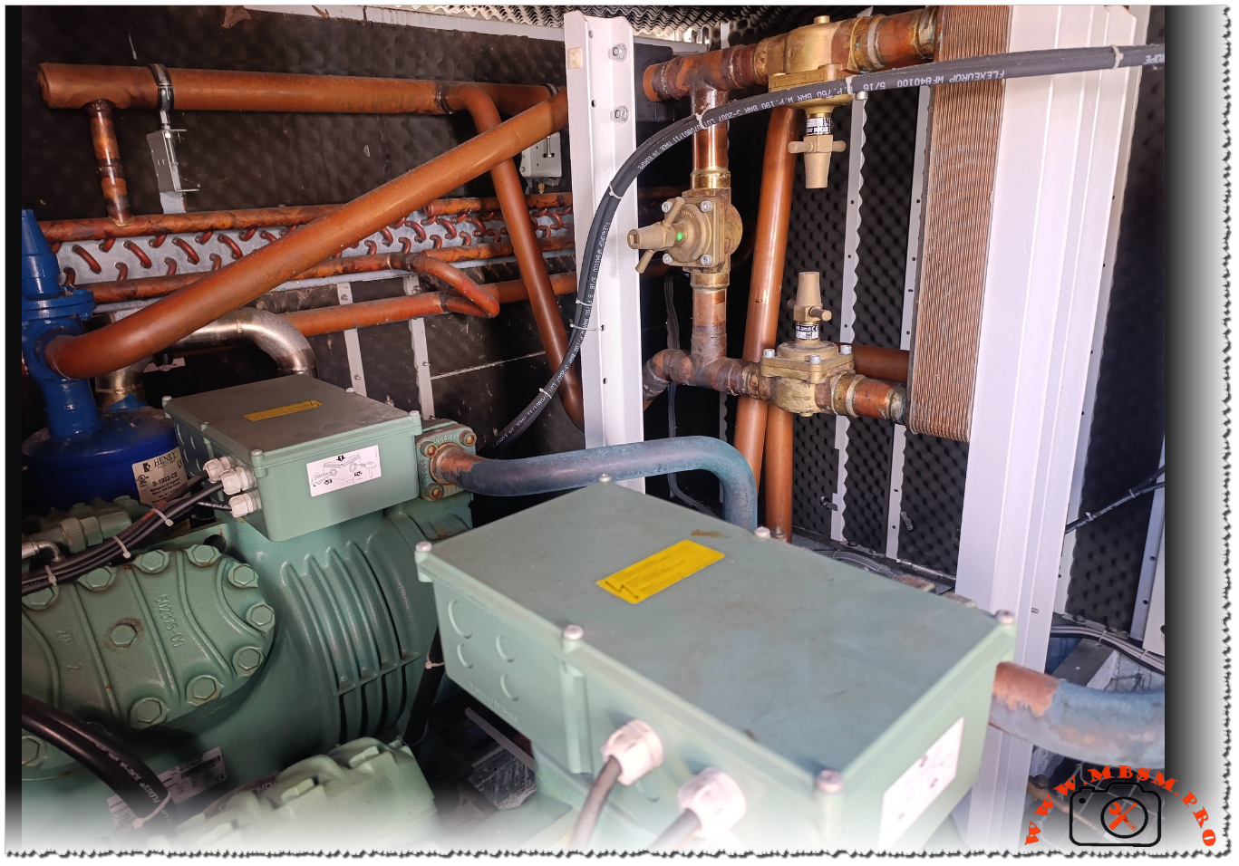
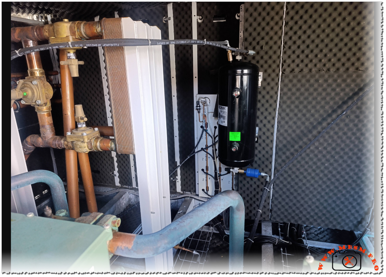
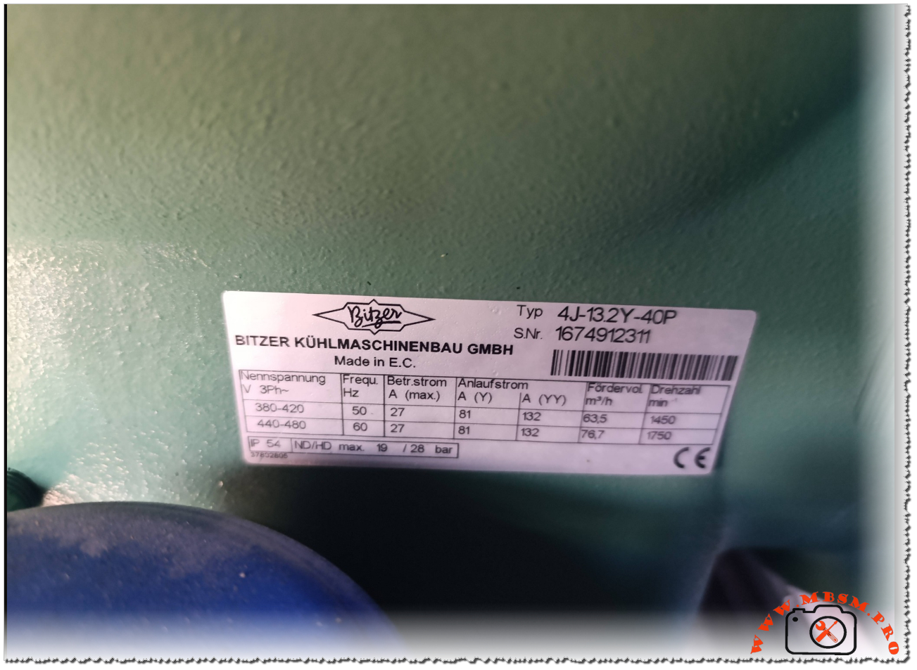
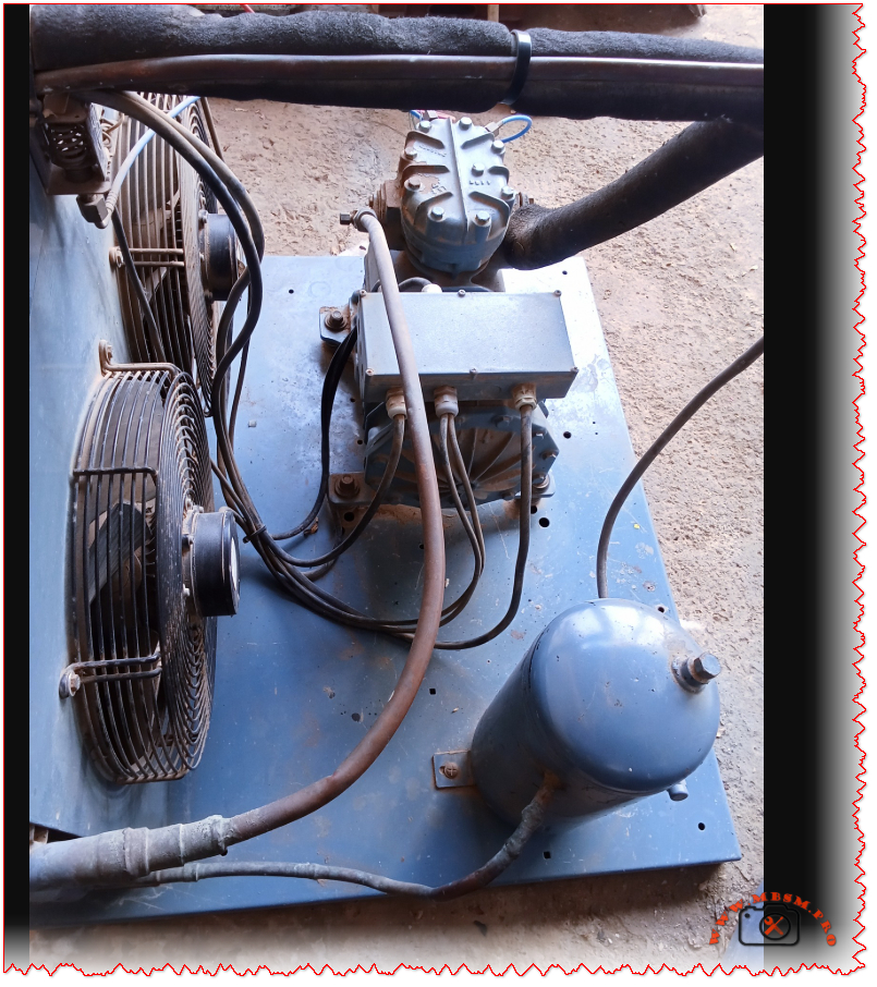
The Bitzer 4J‑13.2Y‑40P is a semi‑hermetic reciprocating compressor widely used in commercial refrigeration and process cooling installations around the world. It is designed for three‑phase power supplies and offers reliable operation in medium‑ to high‑temperature applications. Understanding its nameplate is essential for safe commissioning, correct electrical connection, and accurate system sizing.
Electrical characteristics
The identification plate lists the nominal three‑phase voltage ranges of 380–420 V at 50 Hz and 440–480 V at 60 Hz, showing that this model is suitable for international grids and export equipment. This flexibility allows installers to deploy the same compressor frame in regions with different mains standards, provided the motor protection and wiring are adjusted accordingly.
At 50 Hz, the maximum running current is specified at 27 A, while the starting current in star (Y) connection reaches 81 A and in part‑winding (YY) configuration 132 A. At 60 Hz, the maximum running current remains 27 A, but the higher frequency increases the starting demand and speed, so the electrical design of contactors, circuit‑breakers and cables must respect these values.
Key electrical data
| Parameter | 50 Hz value | 60 Hz value |
|---|---|---|
| Nominal voltage | 380–420 V | 440–480 V |
| Max. running current | 27 A | 27 A |
| Starting current (Y) | 81 A | 81 A |
| Starting current (YY) | 132 A | 132 A |
Performance and operating limits
The nameplate also indicates the theoretical displacement flow rate and motor speed for each frequency. At 50 Hz the compressor delivers 63.5 m³/h at 1450 rpm, while at 60 Hz the flow rises to 76.7 m³/h at 1750 rpm, which directly influences cooling capacity and requires recalculation of expansion valve and piping selections when changing frequency. These figures are important for designers who convert catalog capacities to real site conditions, especially in retrofits where a 50 Hz machine is driven from a 60 Hz supply or via a frequency inverter.
The enclosure rating is IP54, and the plate notes the combination “ND/HD max. 19/28 bar”, indicating the maximum permissible operating pressure on the low‑ and high‑pressure sides of the compressor shell. Respecting these limits is crucial for safety valves, pressure switches and leak testing procedures during commissioning and maintenance.
Performance snapshot
| Frequency | Flow rate (m³/h) | Speed (rpm) | Max. shell pressure (ND/HD) |
|---|---|---|---|
| 50 Hz | 63.5 | 1450 | 19 / 28 bar |
| 60 Hz | 76.7 | 1750 | 19 / 28 bar |
Practical guidance for installers
For installers and service technicians, the nameplate of the 4J‑13.2Y‑40P acts as the main reference for electrical protection settings, cable sizing and motor starting method. Checking that the site voltage matches one of the listed ranges is a first step before any connection, followed by the choice between star‑delta, part‑winding or direct‑on‑line starting depending on the available switchgear and network capacity. The running current values help to set thermal overload relays and electronic motor protection units, reducing the risk of nuisance trips or motor damage under heavy load.
During commissioning, technicians should also compare the actual operating pressures and temperatures with the limits derived from Bitzer’s application range diagrams for this model. This ensures that the compressor runs within its safe envelope when paired with modern refrigerants, oil types and system designs recommended by the manufacturer. Such discipline is especially important for demanding applications like supermarket racks, process chillers and cold‑storage plants where the 4J‑13.2Y‑40P is often installed.
Documentation and further resources
Bitzer provides full technical information, performance curves and motor data sheets for the 4J‑13.2Y‑40P, which complement the basic figures printed on the nameplate. These documents are available in the official digital library and are regularly updated to reflect changes in approved refrigerants, oils and electrical components. Engineers and technicians should always consult the latest documentation before selecting replacement compressors or redesigning existing installations, as updated guidelines may affect allowed operating envelopes and accessory choices.