Technical Analysis of High-Performance Hermetic Compressors: GQY80AT and ATA72XL
Mbsmpro.com, Compressor, GQY80AT vs ATA72XL, 1/4 hp – 1/5 hp, ZEL, Huaguang, R134a, Cooling, 220V, LBP, Refrigerator Repair
Technical Analysis of High-Performance Hermetic Compressors: GQY80AT and ATA72XL
In the world of refrigeration maintenance and professional appliance repair, choosing the right compressor is the difference between a long-lasting fix and a premature system failure. Today, we are diving deep into the technical specifications of two widely used units in the industry: the ZEL GQY80AT and the Huaguang ATA72XL. Both are designed for R134a refrigerant but serve slightly different cooling capacities and applications.
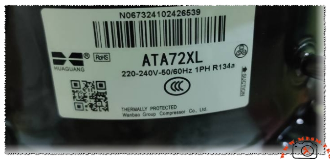
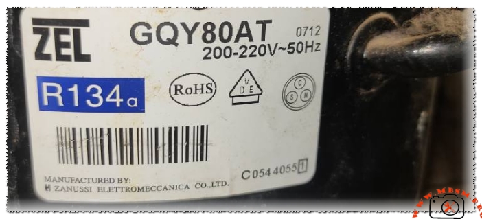
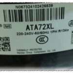
The GQY80AT, manufactured by Zanussi Elettromeccanica (ZEL), has long been a staple in European-designed domestic freezers and large refrigerators. It is a robust 1/4 HP unit known for its high starting torque and reliability in fluctuating voltage environments. On the other hand, the Huaguang ATA72XL is a highly efficient 1/5 HP+ (often treated as a strong 1/5 or light 1/4) compressor from the Wanbao Group. It is frequently seen in modern energy-efficient refrigerators where low noise and high Coefficient of Performance (COP) are prioritized.
Technical Specification Table
| Model | ZEL GQY80AT | Huaguang ATA72XL |
| Utilization | LBP (Low Back Pressure) | LBP (Low Back Pressure) |
| Domaine | Freezing / Cooling | Freezing / Cooling |
| Cooling Wattage (-23.3°C) | 198 W | 185 W |
| Cubic Feet Capacity | 12 – 16 cu.ft. | 10 – 14 cu.ft. |
| Liters Capacity | 350 – 450 L | 280 – 400 L |
| Kcal/h | 170 kcal/h | 159 kcal/h |
| Oil Type & Quantity | POE (Ester) / 200ml | POE (Ester) / 180ml |
| Horsepower (HP) | 1/4 HP | 1/5 HP+ |
| Refrigerant Type | R134a | R134a |
| Power Supply | 200-220V / 50Hz | 220-240V / 50-60Hz |
| Cooling Capacity (BTU) | 676 BTU/h | 631 BTU/h |
| Motor Type | RSIR / RSCR | RSIR |
| Displacement | 8.1 cm³ | 7.2 cm³ |
| Winding Material | Copper | Copper |
| Pressure Charge | 0.5 – 0.8 Bar (Running) | 0.4 – 0.7 Bar (Running) |
| Capillary Size | 0.031″ / 3.0m | 0.028″ / 3.0m |
| Temperature Function | -35°C to -10°C | -30°C to -10°C |
| Cooling Method | Static (No Fan) | Static (No Fan) |
| Commercial Use | Light Commercial/Domestic | Domestic |
| Amperage (FLA) | 1.3 A | 1.1 A |
| LRA (Locked Rotor) | 12 A | 10 A |
| Relay Type | PTC | PTC |
| Capacitor | Optional (4-5uF) | No |
| Origin | China (Zanussi Tech) | China (Wanbao) |
Efficiency Metrics (COP) Performance Data
| Evaporating Temp (°C) | Cooling Capacity (Watts) | Power Consumption (Watts) | COP (W/W) |
| -30 | 145 | 125 | 1.16 |
| -25 | 182 | 148 | 1.23 |
| -23.3 (Standard) | 198 | 155 | 1.27 |
| -20 | 235 | 170 | 1.38 |
| -15 | 305 | 195 | 1.56 |
| -10 | 390 | 220 | 1.77 |
Professional Replacement Guide
When the original unit is no longer available, these replacements offer the same displacement and cooling curve characteristics.
5 Direct Replacements (R134a Gas)
- Embraco FFI7.5HAK: A heavy-duty 1/4 HP equivalent with high reliability.
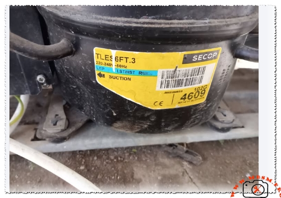
- Secop (Danfoss) TLES7F: Excellent efficiency for domestic LBP applications.
- LG MA72LAEP: A very quiet alternative with similar mounting footprints.
- Tecumseh THG1365YS: Known for high tolerance to high ambient temperatures.
- Samsung NC44A94ALH: A compact but powerful alternative.
5 Alternative Replacements (R600a Gas Conversion)
Note: Converting to R600a requires a complete system flush and a dedicated R600a capillary/filter.
- Secop TLES7.5KK.4: The industry standard for R600a 1/4 HP swaps.
- Embraco EMX70CLC: High COP unit for energy-conscious repairs.
- Jiaxipera NT1114Y: Widely used in modern inverter-to-fixed-speed conversions.
- Donper LU72CZ1: A budget-friendly R600a unit with stable performance.
- Wanbao ATA72XL (R600a Version): The direct isobaric sibling of the R134a model.
Expert Engineering Insights & Tips
When installing these compressors, pay close attention to the displacement differences. The GQY80AT (8.1cc) is slightly more powerful than the ATA72XL (7.2cc). If you are replacing a ZEL with a Huaguang, the cooling might be slightly slower in a large chest freezer. Conversely, using a ZEL to replace a Huaguang may result in shorter cycle times, which can lead to higher wear on the relay if not monitored.
Technician’s Checklist:
- Triple Vacuum: Always pull down to 500 microns to ensure all moisture is removed from the POE oil.
- Filter Drier: Never reuse a filter. Always install a new 20g or 30g XH-9 molecular sieve drier.
- Winding Check: Before brazing, verify the Common, Start, and Main terminals. The GQY80AT has a standard triangular pin configuration.
- Heat Dissipation: Ensure the condenser coils are cleaned. These static-cooled compressors rely heavily on natural convection or the external cabinet skin for heat exchange.
Focus Keyphrase: ZEL GQY80AT and Huaguang ATA72XL Compressor Specifications and Replacement Guide
SEO Title: Mbsmpro.com, Compressor, GQY80AT, ATA72XL, 1/4 HP, R134a, Technical Data
Meta Description: Detailed technical analysis of ZEL GQY80AT and Huaguang ATA72XL compressors. Includes BTU, wattage, cooling capacity, and 10 professional replacement models for R134a and R600a. Perfect for refrigeration engineers and professional technicians.
Slug: zel-gqy80at-huaguang-ata72xl-compressor-specs-replacement
Tags: Mbsmgroup, Mbsm.pro, mbsmpro.com, mbsm, ZEL, GQY80AT, Huaguang, ATA72XL, R134a, 1/4 HP, 1/5 HP, Embraco FFI7.5HAK, Secop TLES7F, LG MA72LAEP, Tecumseh THG1365YS, Refrigeration Repair, Compressor Replacement, LBP Compressor
Excerpt: Choosing between the ZEL GQY80AT and Huaguang ATA72XL requires a deep understanding of displacement and cooling wattage. This professional guide breaks down the 198W capacity of the GQY80AT versus the 185W of the ATA72XL, providing essential data for technicians, including oil types, motor configurations, and a comprehensive list of cross-compatible replacement models.