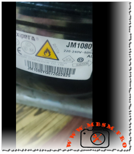
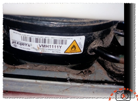
Jiaxipera JM1080Y Compressor 1/8 hp R600a, capillary 0.028 2.5m
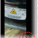
Mbsmpro.com, Compressor, JM1080Y, 1/8 hp, Jiaxipera, Cooling, R600a, 100 W, 0.6 A, 1Ph 220–240V 50Hz, LBP, RSCR, -35°C to -10°C, cooling or freezing
Jiaxipera JM1080Y Technical Specifications
This compressor is a high-efficiency model designed for R600a refrigerant and Low Back Pressure (LBP) applications.
Compressor Performance Data
- Horsepower (HP): Rated at approximately 1/8 HP (or 1/8+ HP).
- Cooling Capacity: Reaches up to 100 Watts (approximately 341 BTU/h) according to ASHRAE standards.
- Displacement: 6.0 $cm^3$.
- Refrigerant Type: R600a (Isobutane).
Recommended Capillary Tube Sizes
To achieve the best performance in domestic refrigeration units, use the following specifications:
- Primary Option: 0.031 inch (0.8 mm) diameter with a length of 3 meters.
- Secondary Option: 0.028 inch (0.7 mm) diameter with a length of 2.5 meters.
Technical Installation Notes
- Precision Charging: Because R600a is used, the system must be charged strictly by weight (in grams) as indicated on the appliance’s data plate.
- Sensitivity: This refrigerant is highly sensitive to even minor deviations in gas volume.
- Vacuum Process: A thorough vacuum (20–30 minutes) is mandatory to ensure the system is completely free of air and moisture before charging.
The refrigeration industry relies on precision components to maintain efficiency and food safety. Among these, the Jiaxipera JM1080Y stands out as a high-performance, hermetic reciprocating compressor engineered for modern domestic appliances. Designed for low-back-pressure (LBP) applications, this unit is commonly found in energy-efficient refrigerators and freezers where quiet operation and low energy consumption are paramount.
Operating on R600a (Isobutane), the JM1080Y reflects the global shift toward environmentally friendly refrigerants with low global warming potential. Its design incorporates a robust motor and optimized internal mechanics to ensure longevity and consistent cooling capacity even under varying thermal loads.
Technical Specifications: Jiaxipera JM1080Y
| Feature | Specification |
| Model | JM1080Y |
| Utilisation (mbp/hbp/lbp) | LBP (Low Back Pressure) |
| Domaine (Freezing/Cooling) | Freezing and Cooling |
| Cooling wattage at -23.3°C | 100 W |
| Cubic feet (approx. cooling capacity) | 6.5 to 8.5 cu. ft. |
| Litres (approx. cooling capacity) | 185 to 240 Liters |
| Kcal/h | 86 Kcal/h |
| Oil Type and Quantity | Mineral Oil / 180 ml |
| Horsepower (HP) | 1/8 hp |
| Refrigerant Type | R600a |
| Power Supply | 220–240V / 50Hz |
| Cooling Capacity BTU/h | 341 BTU/h |
| Motor Type | RSCR (Resistance Start – Capacitor Run) |
| Displacement | 6.2 cm³ |
| Winding Material | Copper |
| Pression Charge | Low Pressure |
| Capillary (Suggested) | 0.026″ – 0.031″ |
| Refrigerator Models | Bosch, Haier, Samsung, Beko, Hisense |
| Temperature Function | -35°C to -10°C |
| With fan or no | Static (Natural cooling) |
| Commercial or no | No (Domestic / Household) |
| Amperage in function | 0.55 A – 0.6 A |
| LRA (Locked Rotor Amps) | 4.6 A |
| Type of relay | PTC Starter |
| Capacitor Value | 2.5 µF / 450V |
| Country of Origin | China |
Efficiency Metrics (COP) & Performance Data
The coefficient of performance (COP) is a critical indicator of how much cooling work the compressor does relative to the electrical energy it consumes.
| Evaporating Temp (°C) | Cooling Capacity (Watts) | Power Consumption (Watts) | COP (W/W) |
| -35 | 58 | 51 | 1.14 |
| -30 | 76 | 60 | 1.27 |
| -23.3 (Standard) | 100 | 68 | 1.47 |
| -20 | 118 | 74 | 1.59 |
| -15 | 146 | 82 | 1.78 |
| -10 | 180 | 92 | 1.96 |
Comparison: JM1080Y vs. Industry Standard 1/10 HP Units
While many 1080 models are rated at 1/10 HP, the JM1080Y is frequently categorized as a 1/8 HP unit due to its higher displacement (6.2 cm³) compared to the standard 5.5 cm³ found in models like the NE1080Y. This extra displacement provides a higher cooling reserve, making it more resilient in high-ambient temperature conditions.
Replacement Cross-Reference
5 Replacements (Same Gas: R600a)
- Embraco: EMX32CLC
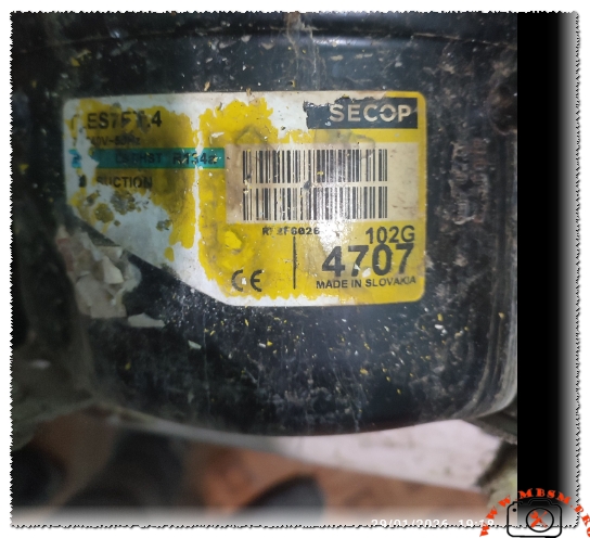
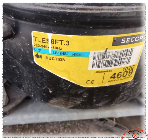
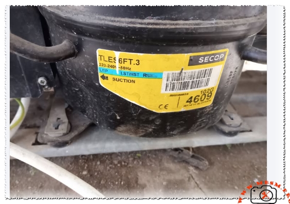
- Secop (Danfoss): TLES5.7KK.3
- Huayi: HYE55Y
- Donper: A90CY
- LG: CMA057LBJH
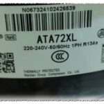
5 Replacements (Other Gas: R134a)
Note: Converting systems between refrigerants requires a total oil flush and system cleaning.
- Jiaxipera: ND1080Y
- Embraco: EMT32HLP
- Secop: TLS5F
- Cubigel: GL45AA
- Tecumseh: THG1335YS
Expert Engineering Advice & Notice
- Refrigerant Safety: R600a is highly flammable. Always ensure there are no ignition sources in the work area and use a vacuum pump specifically rated for hydrocarbons.
- Vacuum & Moisture: A deep vacuum of 500 microns or less is mandatory. Mineral oil in R600a systems is sensitive to moisture, which can cause internal acid formation.
- Capillary Selection: If replacing a compressor with a different brand, always verify the capillary tube size. A mismatch can lead to liquid slugging or poor evaporator utilization.
- Static Cooling: This compressor is designed for static cooling. Do not enclose it in a tight space without adequate airflow, as overheating will drastically reduce the lifespan of the motor windings.
Focus Keyphrase: Jiaxipera JM1080Y Compressor 1/8 hp R600a
SEO Title: Mbsmpro.com, Jiaxipera JM1080Y, 1/8 HP, R600a Refrigerator Compressor
Meta Description: Detailed technical data for the Jiaxipera JM1080Y compressor. 1/8 HP, 100W cooling capacity, R600a refrigerant. Includes wiring, COP tables, and compatible replacements for LBP applications.
Slug: jiaxipera-jm1080y-compressor-1-8-hp-r600a-specs
Add Tags: Mbsmgroup, Mbsm.pro, mbsmpro.com, mbsm, Jiaxipera, JM1080Y, R600a Compressor, 1/8 HP Compressor, Refrigerator Repair, EMX32CLC replacement, TLES5.7KK.3, HYE55Y, LBP Compressor, Cooling Capacity 100W.
Excerpt: The Jiaxipera JM1080Y is a high-performance 1/8 hp compressor specifically designed for R600a refrigerant in domestic LBP applications. With a cooling capacity of 100W and a displacement of 6.2 cm³, it provides a quiet, energy-efficient solution for modern refrigerators. This guide covers technical data, performance metrics, and professional field advice for technicians.