Danfoss Secop SLV15CNK / SLV15CNK.2 — Complete Technical Review & Replacement Guide

What Is the Danfoss SLV15CNK?
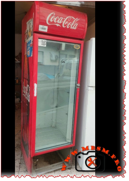
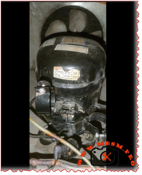
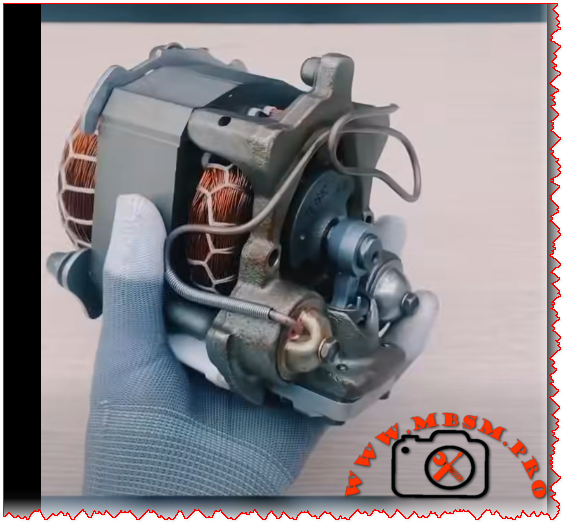
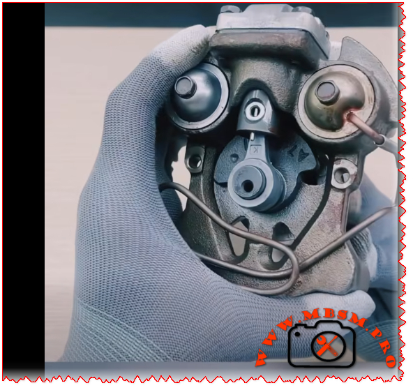
If you’ve ever opened the back panel of a commercial chest freezer or a light commercial display case and found a compact, brushless compressor with a controller module attached to it, there’s a good chance you were looking at a Danfoss Secop SLV15CNK. This variable-speed hermetic compressor is one of the most widely deployed LBP (Low Back Pressure) units in European and international commercial refrigeration — and for good reason.
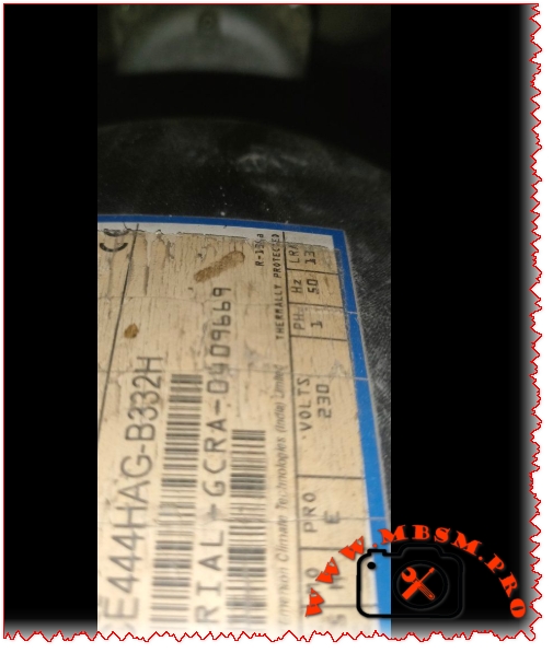
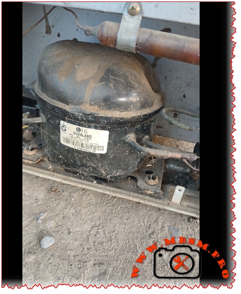
Originally built under the Danfoss brand before the compressor division was spun off as Secop GmbH in 2010, the SLV15CNK has carved out a reliable reputation across commercial food retail, light industrial cooling, and even medical cold-chain applications. The unit pictured above — serial reference 561108N4, profile 104H — is the standard 220–240V, 50/60 Hz variant using R290 (propane) refrigerant, one of the most eco-friendly natural refrigerants available today.
Complete Technical Specifications Table
| Parameter | Value |
|---|---|
| Model | SLV15CNK / SLV15CNK.2 |
| Utilisation (MBP/HBP/LBP) | LBP only (Low Back Pressure) |
| Domain (Freezing/Cooling) | Deep Freezing — evap. temp. –40°C to –10°C |
| Cooling Wattage at –23°C | ~446 W (nominal at standard LBP conditions) |
| Cubic Feet Cooled | ~7–10 ft³ (small to medium chest freezer) |
| Litres Cooled | ~200–280 litres |
| Kcal/h | ~383 Kcal/h |
| TON | ~0.127 TON of refrigeration |
| Oil Type & Quantity | Polyolester (POE) — 600 cm³ |
| Horsepower (HP) | 5/8 HP (~0.60 HP) |
| Refrigerant Type | R290 (Propane) — max charge 150 g |
| Power Supply | 220–240V / 1Ph / 50–60 Hz (range: 180–254V) |
| Cooling Capacity BTU | ~1521 BTU/h (LBP nominal) |
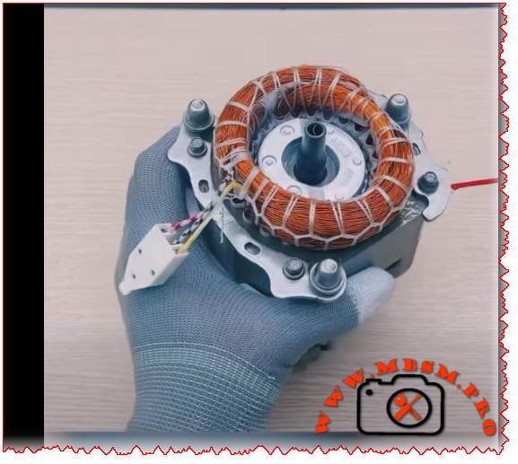
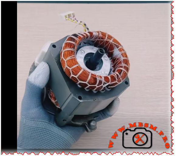
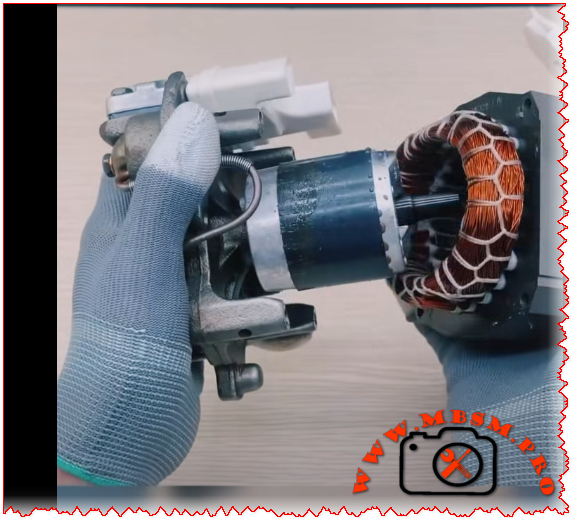
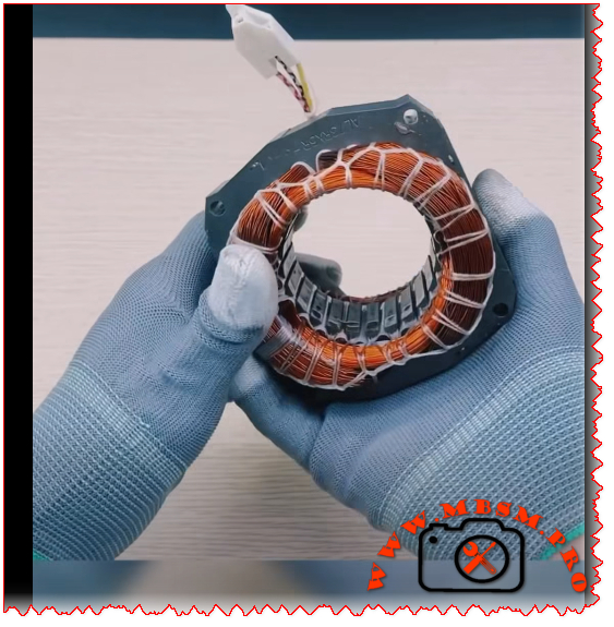
| Motor Type | Permanent Magnet (TRI — 3-phase inverter driven) |
| Displacement | 15.28 cm³ |
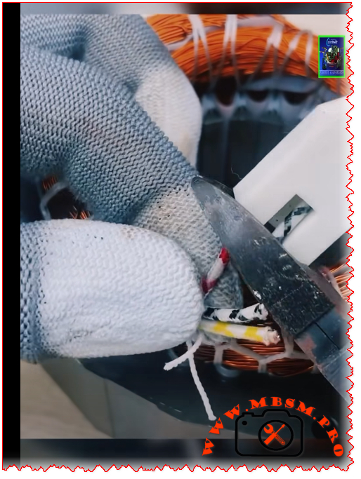
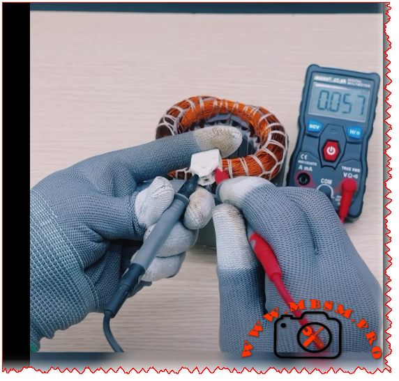
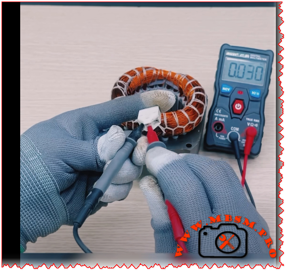
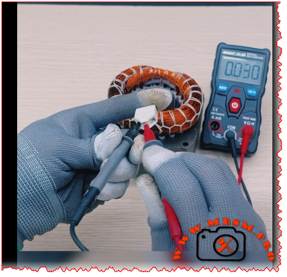
| Winding Material | Copper (3-phase windings, resistance ~7.7 Ω at 25°C) |
| Pression Charge | LBP / LST — max condensing temp 55°C (65°C short-term) |
| Capillary | Approx. 3m / Ø0.31 mm (application-dependent — verify with OEM data) |
| Compatible Refrigerator Models | AHT Deep Freezers, light commercial chest freezers, display cases, ice machines, beverage coolers |
| Temperature Function | –40°C to –10°C evaporating; –35°C practical freezer operation |
| With Fan or Not | Yes — F2 fan cooling required (3.0 m/s airflow on compressor & controller) |
| Commercial or Domestic | Commercial (light commercial / food retail) |
| Amperage in Function | Max 4.6 A |
| LRA (Locked Rotor Amperage) | Electronic cut-off (no traditional LRA — inverter-controlled) |
| Type of Relay | No traditional relay — uses 105N46xx Series SLV Electronic Controller |
| Capacitor | No start/run capacitor — inverter-driven (variable speed 2000–4000 RPM) |
| Country of Origin & Export | Manufactured in Slovakia (Secop GmbH) — exported globally: EU, UK, Middle East, North Africa, Australia, Asia |
What Makes This Compressor Special?
Variable Speed Technology
Most technicians encounter fixed-speed compressors day in and day out. The SLV15CNK breaks that mold entirely. It’s a variable speed drive (VSD) compressor, meaning its speed adapts continuously between 2000 and 4000 RPM based on thermal demand. The result is dramatically reduced energy consumption during low-load periods, less mechanical wear, and quieter operation — all things that matter enormously in a commercial food retail environment where a freezer runs 24/7, 365 days a year.
R290 — The Natural Refrigerant Advantage
R290 (propane) is not new, but its adoption in commercial compressors has accelerated rapidly in recent years thanks to its near-zero Global Warming Potential (GWP = 3) compared to the synthetic alternatives it replaces. The SLV15CNK uses a maximum charge of just 150 grams, which keeps it below the safety threshold for flammable refrigerant use in occupied spaces. That tiny charge, combined with propane’s excellent thermodynamic properties, means this compressor achieves high efficiency with a very light environmental footprint.
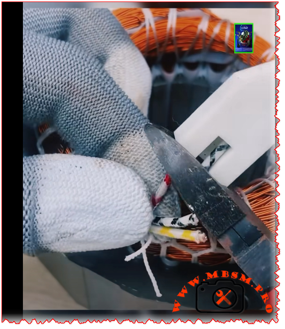
The Controller Dependency
One detail technicians absolutely must not overlook: this compressor will not function without its dedicated SLV electronic controller (105N46xx series). The label on the unit itself clearly states “Only with SLV controller.” This is not a traditional hermetic compressor you can simply wire up to a relay and a capacitor. The controller handles speed regulation, current protection, speed monitoring, and thermal protection all in one unit. Replacing or sourcing this controller is as important as finding the compressor itself.
Fan Cooling Is Mandatory
At all ambient conditions (32°C, 38°C, and 43°C), the datasheet specifies F2 cooling — meaning fan airflow of at least 3.0 m/s directly on both the compressor body and the electronic controller unit. Attempting to run this compressor without proper forced airflow will trigger thermal protection and lead to premature failure. This is a common oversight when installers replace the compressor without checking the cabinet’s fan arrangement.
Replacement Compressors — Same Gas (R290)
When the SLV15CNK reaches end of life or fails, the most straightforward replacements use the same R290 refrigerant. Here are five proven options:
| # | Replacement Model | Brand | Notes |
|---|---|---|---|
| 1 | SLV15CNK.2 (104H8541) | Secop/Danfoss | Direct drop-in replacement — latest revision |
| 2 | SLV12CNK.2 | Secop/Danfoss | Slightly lower displacement, same gas and controller family |
| 3 | SLV20CNK.2 | Secop/Danfoss | Higher capacity option — same R290/controller platform |
| 4 | NLV14CNK | Secop/Danfoss | Fixed-speed variant on R290 LBP — requires relay/capacitor |
| 5 | SCM10CNX.2 | Secop | R290, standard hermetic, LBP — no inverter controller needed |
Replacement Compressors — Different Refrigerant
If R290 is not available in your region, or if you’re retro-fitting an older system, here are five equivalents using alternative refrigerants with comparable capacity:
| # | Replacement Model | Brand | Refrigerant | Notes |
|---|---|---|---|---|
| 1 | SC15G | Secop/Danfoss | R404A / R507A | Classic LBP hermetic, no controller needed |
| 2 | NL11MF | Secop/Danfoss | R134a | LBP/MBP, standard hermetic |
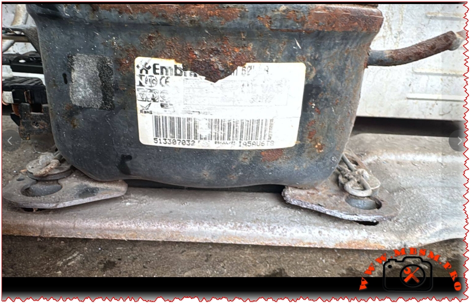
| 3 | CAJ9513Z | Embraco | R404A | Direct LBP replacement at similar capacity |
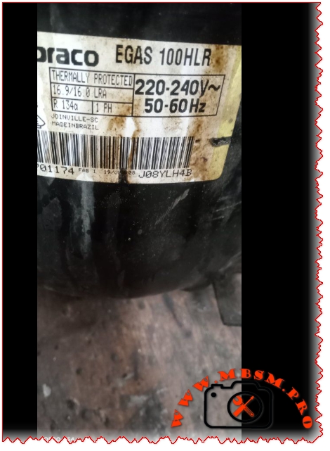
| 4 | NEBL2134Z | Embraco | R600a | For domestic/light LBP applications |
| 5 | MTZ32-4VM | Danfoss | R452A/R404A | Slightly oversized but compatible for retrofits |
⚠️ Important: Switching refrigerants requires changing the oil type, capillary tube, and verifying all safety certifications. Always consult the system manufacturer before cross-refrigerant replacement.
Typical Applications — Which Freezers Use This Compressor?
The SLV15CNK is the heart of many products you’ll recognize from the supermarket floor:
- AHT Australian series chest freezers (confirmed via MBSM documentation)
- Light commercial open-top island freezers
- Vertical display freezer cabinets (small commercial)
- Beverage coolers with sub-zero requirements
- Frozen food display cases at petrol stations and convenience stores
- Ice cream chest cabinets in retail environments
The AHT connection is particularly well-documented — AHT is a major manufacturer of commercial freezers widely deployed across European and African retail chains, and the SLV15CNK is one of their standard compressor choices.
Installation & Service Notes
A few practical points every technician should keep in mind when working with this unit:
Controller wiring: Always refer to the 105N46xx wiring diagram. Polarity and signal connections matter — the controller is not interchangeable between all SLV variants.
Refrigerant handling: R290 is flammable (Class A3). Work in ventilated areas, avoid open flames, and use an R290-certified manifold gauge set. The 150g charge limit means leaks are rare but must be taken seriously.
Oil compatibility: POE oil is mandatory with R290 in this application. Do not substitute mineral oil or alkylbenzene — POE is pre-filled at the factory at 600 cm³.
Mounting vibration: The compressor ships with rubber mounting grommets. Always re-use or replace them — running on a hard mount increases noise and mechanical fatigue.
Capillary tube: The reference capillary for AHT applications is approximately 3m / 0.31mm diameter, but always measure and verify against the original system before cutting new tubing.
Why This Compressor Matters in 2025 and Beyond
The refrigeration industry is at a turning point. Synthetic refrigerants with high GWP are being phased out under F-Gas regulations in Europe and similar legislation worldwide. The SLV15CNK — running on propane with a permanent magnet variable-speed motor — represents exactly the direction the industry is heading: natural refrigerants, intelligent speed control, and reduced energy consumption without compromising reliability.
For service technicians, understanding this platform deeply isn’t just useful today — it’s preparation for the next decade of commercial refrigeration work.