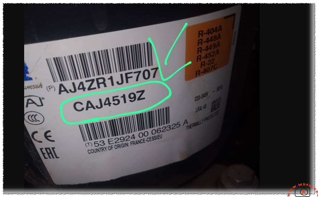
I charged the compressor CAJ4519Z with R407 gas, and upon startup, some frost appeared on the return line and expansion valve, even though the cooling was fine. Is this normal? Note that it’s a refrigeration room, not a freezer.
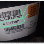
Regarding the compressor in the photo (Tecumseh CAJ4519Z) used in a cold room (chilling/positive temperature) with R-407C gas, finding frost on the suction line and the expansion valve is not normal for this type of application.
While the cooling might seem “good” now, frost on the suction line indicates that liquid refrigerant is not fully evaporating in the evaporator and is returning to the compressor.
Here is a technical breakdown of why this is happening and how to fix it:
1. Low Superheat (Expansion Valve Adjustment)
This is the most common cause. If the expansion valve is open too wide, it allows too much liquid into the evaporator.
- The Risk: Liquid refrigerant can reach the compressor (Liquid Slugging), which can break the internal valves of the CAJ4519Z compressor.
- The Fix: You need to adjust the Superheat. For a positive temperature cold room, the superheat should be between 5°C and 8°C. If it is lower, slightly close the expansion valve (turn the adjustment screw clockwise) in half-turn increments and wait 15–20 minutes to see the effect.
2. Overcharging the System
If you added too much R-407C, the excess refrigerant stays in the evaporator and suction line as a liquid/gas mix, causing frosting.
- Note on R-407C: This is a “blend” refrigerant. It must always be charged in the liquid state (tank upside down). If you charged it as a vapor, the mixture ratio might be wrong, affecting performance.
- The Fix: Check the sight glass (if available) and monitor the pressures. For R-407C in a cold room at 0°C to +4°C, your suction pressure should typically be around 45 to 55 PSI.
3. Poor Airflow at the Evaporator
If the heat exchange is poor, the refrigerant won’t boil off into a gas.
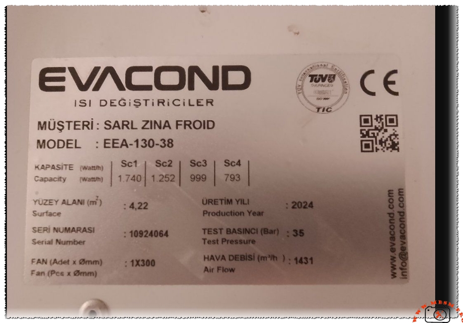
- Check the Evaporator (EVACOND unit in your photo):
- Are the fans spinning at the correct speed?
- Are the fins dirty or clogged?
- Is there already an ice buildup on the evaporator coils blocking the air?
4. Expansion Valve Sensing Bulb
Check the location of the expansion valve’s sensing bulb.
- If the bulb is loose or not insulated properly, it “thinks” the pipe is warm and opens the valve too much, flooding the suction line.
- The Fix: Ensure the bulb is tightly clamped to the suction pipe (at the 2 o’clock or 10 o’clock position) and well-insulated.
Summary Recommendation:
Frost should generally stop at the outlet of the expansion valve or the very beginning of the evaporator. If the frost is traveling all the way back to the compressor:
- Slightly close the expansion valve.
- Verify the airflow over the evaporator.
- Ensure you haven’t overcharged the system.
Allowing frost to reach the compressor will eventually lead to mechanical failure or “slugging,” which will destroy the compressor.
Focus Keyphrase: Comprehensive Technical Guide for Tecumseh CAJ4519Z Compressor Performance in R407C and R404A Medium High Back Pressure Refrigeration Systems
SEO Title: Mbsmpro.com, Compressor, CAJ4519Z, 1 HP, Tecumseh, Cooling, R404A, R407C, 220-240V, MHBP, Hermetic Reciprocating
Meta Description: Explore the professional specifications of the Tecumseh CAJ4519Z compressor. Learn about its 1 HP capacity, multi-refrigerant compatibility, and expert field advice for maintaining optimal superheat in commercial cold rooms.
Slug: tecumseh-caj4519z-compressor-technical-specifications-guide
Tags: Mbsmgroup, Mbsm.pro, mbsmpro.com, mbsm, Tecumseh, CAJ4519Z, AJ4ZR1JF707, R404A, R407C, R448A, R449A, R452A, Replacement Compressor, Commercial Refrigeration, Cold Room Compressor, Danfoss MTZ22, Embraco NEK6217GK, Copeland ZB15KCE, Bitzer 2KES-05, Bristol H23A383DBL
Excerpt: The Tecumseh CAJ4519Z stands as a benchmark in commercial refrigeration, offering robust performance for Medium and High Back Pressure (MHBP) applications. Engineered for versatility, it supports a wide array of refrigerants including R404A and R407C. This professional analysis covers technical data, wiring configurations, and essential maintenance practices for field engineers working on refrigeration units.
Mbsmpro.com, Compressor, CAJ4519Z, 1 HP, Tecumseh, Cooling, R404A, R407C, 220-240V 50Hz, MHBP, CSR, 34.4 cm³
The Tecumseh CAJ4519Z is a high-performance hermetic reciprocating compressor widely utilized in the commercial refrigeration sector. Known for its reliability in medium to high evaporating temperature ranges, this unit is a staple for walk-in coolers, display cases, and industrial liquid chillers. Its “AJ” series design focuses on thermal efficiency and mechanical durability, making it a preferred choice for technicians demanding longevity in demanding environments.
Technical Specification Table
| Attribute | Specification Details |
| Model | CAJ4519Z |
| Utilisation | MHBP (Medium/High Back Pressure) |
| Domaine | Cooling / Air Conditioning / Commercial Chilling |
| Oil Type and Quantity | POE (Polyolester) / 887 ml |
| Horsepower (HP) | 1 HP (Nominal) |
| Refrigerant Type | R404A, R448A, R449A, R452A, R22, R407C |
| Power Supply | 220-240V ~ 50Hz |
| Cooling Capacity BTU | ~15,500 BTU/h (at +7.2°C Evaporating Temp) |
| Motor Type | CSR (Capacitor Start – Run) |
| Displacement | 34.4 cm³ |
| Winding Material | High-Grade Copper |
| Pressure Charge | High Pressure (Nitrogen Holding Charge) |
| Capillary / Expansion | Expansion Valve (TXV) Recommended |
| Compatible Equipment | Cold Rooms, Bottle Coolers, Industrial Chillers |
| Temperature Function | -15°C to +15°C (Evaporating Range) |
| Fan Requirement | Forced Air Cooling Required (350 m³/h minimum) |
| Commercial Use | Yes, Heavy-Duty Commercial Grade |
| Amperage (RLA) | 6.5 A |
| LRA (Locked Rotor Amps) | 45 A |
| Type of Relay | Potential Relay |
| Start/Run Capacitor | Start: 88-108µF / Run: 20µF |
Comparison with Peer Models
When evaluating the CAJ4519Z, it is helpful to compare its displacement and capacity against other industry standards in the 1 HP range.
| Feature | Tecumseh CAJ4519Z | Embraco NEK6217GK | Danfoss SC15GH |
| Displacement | 34.4 cm³ | 14.3 cm³ (LBP/HBP Mix) | 15.28 cm³ |
| Cooling Power | High (Multi-Ref) | Medium (R404A) | Medium (R134a) |
| System Design | CSR | CSIR | CSIR/CSR |
| Oil Compatibility | Multi-Refrigerant POE | POE Only | POE/PAG |
Engineering Insights: Managing Frost and Superheat
In field operations, specifically when retrofitting or charging systems with R407C, technicians may encounter frost on the suction line. From an engineering perspective, frost migrating toward the compressor crankcase is a critical warning sign.
Diagnostic Checkpoint:
- Superheat Calibration: For a positive temperature cold room, the target superheat at the evaporator outlet should be between 5K and 8K. If frost reaches the suction service valve, the superheat is likely near zero, risking liquid slugging.
- R407C Glide: Unlike R404A, R407C has a significant temperature glide. Charging must be performed in the liquid phase to maintain the correct blend ratio.
- Expansion Valve Tuning: If the cooling is effective but frosting occurs, the Thermostatic Expansion Valve (TXV) may be adjusted too “open.” Closing the valve (clockwise) increases superheat and retreats the frost line.
Potential Replacements
5 Replacements (Same Refrigerant – R404A/R407C)
- Danfoss: MTZ22-4VI (Slightly larger, very robust)
- Copeland: ZB15KCE-TFD (Scroll alternative)
- L’Unite Hermetique: CAJ4517Z (Slightly lower capacity)
- Embraco: NT6222GK
- Bitzer: 2KES-05 (Semi-hermetic equivalent)
5 Replacements (Alternative Refrigerants)
- Tecumseh CAJ4492Y: (R134a variant)
- Danfoss SC18G: (R134a high capacity)
- Tecumseh CAJ4511P: (R290 Natural Refrigerant)
- Embraco NEK6213GK: (R404A – slightly smaller)
- Bristol H23A383DBL: (R22/R407C specific)
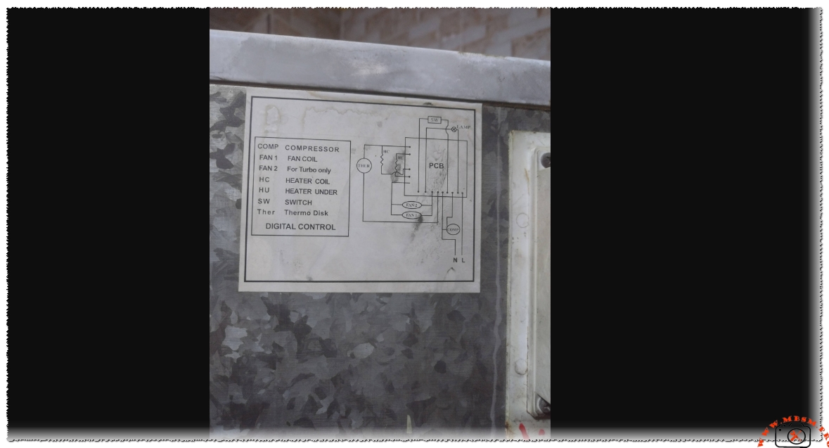
Electrical Wiring Diagram (CSR Logic)
The CSR (Capacitor Start – Run) motor configuration is designed for high starting torque.
- Common (C): Connected to the Overload Protector.
- Start (S): Connected to the Potential Relay (Terminal 2) and Start Capacitor.
- Run (R): Connected to the Main Power and Run Capacitor.
- Potential Relay: Terminals 1 and 2 disconnect the start capacitor once the motor reaches ~75% speed.
Expert Advice and Notice
- Notice: Always use a filter drier compatible with POE oil. POE is highly hygroscopic (absorbs moisture rapidly).
- Benefit: The CAJ4519Z features an internal pressure relief valve, providing an extra layer of safety against system over-pressurization.
- Engineering Tip: When using R407C, ensure the condenser is sized for the additional heat rejection requirements compared to R22. Failure to do so will result in high head pressures and reduced compressor lifespan.