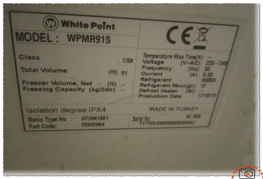
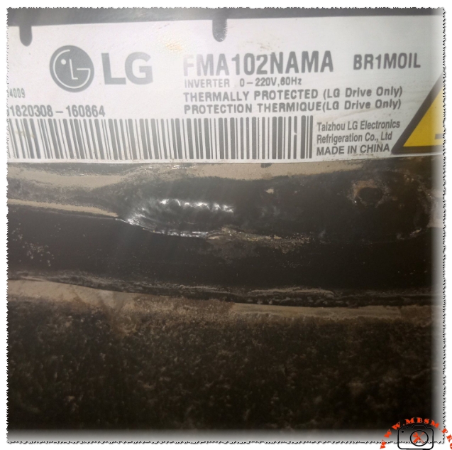
WPMR91S, the refrigerator requires exactly 13 grams of R600a refrigerant.
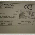
Based on the data provided in the nameplate, the refrigerator requires exactly 13 grams of R600a refrigerant.
Technical Specification Table
| Feature | Details |
| Model | White Point WPMR91S |
| Utilization | LBP (Low Back Pressure) |
| Domaine | Cooling (Mini-Bar / Domestic Refrigerator) |
| Oil Type and Quantity | Mineral or Ester Oil (approx. 160ml) |
| Horsepower (HP) | 1/12 HP |
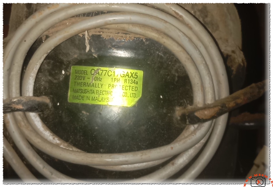
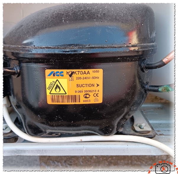
| Refrigerant Type | R600a (Isobutane) |
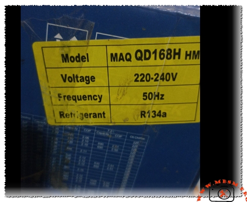
| Power Supply | 220-240V / 50Hz |
| Cooling Capacity BTU | Approx. 310 BTU/h |
| Motor Type | RSIR (Resistance Start – Induction Run) |
| Displacement | 4.0 cm³ to 4.5 cm³ |
| Winding Material | Copper |
| Pression Charge | 0.5 to 1 PSI (Low side running) |
| Capillary | 0.026 ID |
| Compatible Models | Compact refrigerators, Under-counter coolers |
| Temperature Function | +5°C to -18°C (Internal) |
| With Fan or No | No (Static Cooling) |
| Commercial or No | No (Domestic) |
| Amperage in Function | 0.50 A |
| LRA | 2.6 A |
| Type of Relay | PTC Relay |
| Capacitor | No (Standard RSIR) |
Compressor Replacements
5 Replacements (Same Gas – R600a):
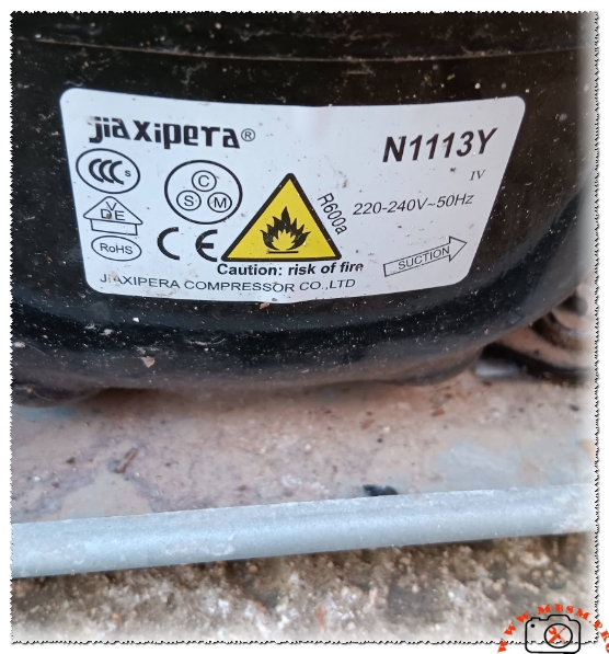
- Jiaxipera T1110Y
- Danfoss/Secop TLES4KK.3
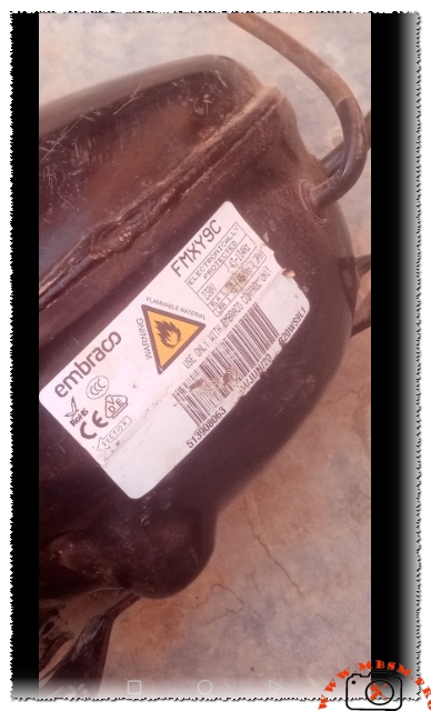
- Embraco EMX20CLC
- Huayi B43H
- Wanbao ASD43Y
5 Replacements (Other Gas – R134a – Requires Flushing):
- Embraco EMI 30HER
- Jiaxipera ZBS1111cy
- Danfoss TLS3F
- Donper S43CZ
- Cubigel GL45AA
Mbsmpro.com, White Point, WPMR91S, Refrigerator, 1/12 hp, R600a, 13g, 0.50 A, 220-240V 50Hz, LBP, Made in Turkey
The White Point WPMR91S represents the modern standard for compact, energy-efficient refrigeration. Manufactured in Turkey, this unit is specifically designed for domestic cooling applications, utilizing the thermodynamic advantages of R600a (Isobutane). Unlike older systems that used heavy refrigerant loads, this high-efficiency cycle operates with a precision charge of only 13 grams.
Thermodynamics and Efficiency
The WPMR91S is built around a Low Back Pressure (LBP) cycle. With a rated current of 0.50 Amperes, the electrical footprint is remarkably low. The integration of R600a allows the compressor to operate at lower pressures compared to R134a, which reduces mechanical wear on the piston and valves, extending the lifespan of the motor.
Engineering Comparison: R600a vs. R134a
| Technical Parameter | WPMR91S (R600a) | Equivalent R134a Unit |
| Mass Charge | 13g | ~45g – 60g |
| Operating Pressure | Below Atmospheric (Vacuum) | Positive Pressure |
| COP (Efficiency) | Higher | Lower |
| Environmental Impact | GWP 3 (Eco-Friendly) | GWP 1430 (High Impact) |
Professional Maintenance Notice
As an expert in the field, I must emphasize that when servicing the WPMR91S, the 13g charge is critical. Because the volume is so small, traditional manifold gauges can trap a significant percentage of the gas in the hoses.
- Scale Precision: Use a digital scale accurate to 1 gram.
- Vacuum: A deep vacuum is mandatory as R600a systems are highly sensitive to moisture and non-condensables.
- Safety: R600a is flammable. Ensure no open flames or sparks are present during the charging process.
Benefits for the End User
The primary benefit of this specific engineering setup is the Isolation Degree IPX4, which provides protection against moisture ingress, making it ideal for various climates. The use of a PTC relay instead of a mechanical start relay further reduces the “click” noise during startup, providing a quieter user experience.
Focus Keyphrase: White Point WPMR91S Refrigerator R600a 13g Compressor
SEO Title: Mbsmpro.com | White Point WPMR91S Specs | R600a 13g Refrigerator Guide
Meta Description: Full technical data for White Point WPMR91S. Features 13g R600a refrigerant, 0.50A current, and 1/12 HP compressor details. Expert guide for replacement and repair.
Slug: white-point-wpmr91s-refrigerator-specs-r600a-13g
Tags: Mbsmgroup, Mbsm.pro, mbsmpro.com, mbsm, White Point, WPMR91S, R600a, Compressor Replacement, Jiaxipera T1110Y, Danfoss TLES4KK.3, Embraco EMX20CLC, Refrigerator Repair Turkey, 1/12 HP Compressor
Excerpt: The White Point WPMR91S is a high-efficiency 91-liter refrigerator utilizing a specialized 13-gram R600a refrigerant charge. Operating at 0.50A, this Turkish-made unit is designed for optimal LBP performance. This guide provides comprehensive technical specifications, compressor cross-references, and engineering insights for professional technicians and hobbyists looking for reliable maintenance data and replacement parts.