Compressor Windings, CSR Terminals
Mbsmpro.com, Compressor, CSR terminals, Common Start Run, PTC relay, overload, start and run capacitor wiring, PSC CSIR CSR motors, multimeter ohm testing
Compressor Windings, CSR Terminals, and Start Devices: Practical Guide for Technicians
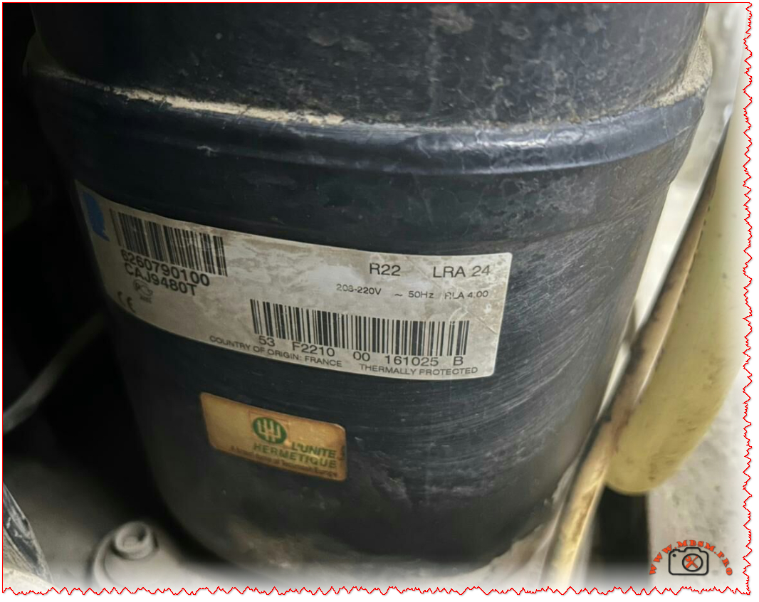
Single‑phase hermetic compressors use three terminals – Common (C), Start (S), and Run (R) – and a combination of overload, relay, and capacitor to start and run safely. Correctly interpreting CSR pin configuration and wiring the starting devices is critical for reliable refrigeration service work and for avoiding repeated compressor burn‑outs.
Understanding C, S, and R terminals
On most refrigeration compressors, the three pins form either a triangle or a straight line, and each pin connects to one or both motor windings inside the shell. When the original diagram is missing, technicians can still identify each terminal by measuring resistance with a digital multimeter.
Typical resistance relationships
*Values vary by model; always compare with the manufacturer’s data sheet when available.
To confirm readings, many trainers recommend writing each resistance value on a sketch of the pin layout and checking that the highest reading equals the sum of the other two. If the numbers do not add up, the compressor may have an open winding or internal damage.
CSR, RSIR, CSIR and PSC motor concepts
Single‑phase hermetic motors are classified by how capacitors and relays are used with start and run windings. The most common arrangements in light commercial refrigeration are RSIR, PSC, CSIR and CSR, each with different starting torque and component requirements.
Motor types and starting characteristics
CSR systems keep a smaller run capacitor in the circuit after startup to improve power factor and running efficiency while the start capacitor is removed by the relay. These motors are common in high‑starting‑torque (HST) versions of commercial compressors where frequent cycling and high condensing pressures are expected.
Overload, PTC relay, and run capacitor wiring
The start device assembly brings together three safety‑critical components: thermal overload, relay (or PTC), and capacitor. Correct wiring ensures that line voltage reaches the run winding continuously, energizes the start winding only during startup, and disconnects the compressor when overcurrent or overheating occurs.
Typical PTC / solid‑state relay and overload wiring (120–240 V)
Before wiring, technicians should verify that the overload has less than 1 Ω resistance when cold and that the relay coil or PTC element shows the manufacturer’s specified resistance range. Any signs of arcing, discoloration or cracked housings are reasons to replace the start device rather than re‑use it.
Multimeter checks and safety best practices
Accurate ohm measurements and ground tests are indispensable when diagnosing compressor failures or confirming correct CSR identification. At the same time, technicians must follow lock‑out/tag‑out procedures and respect the refrigeration system’s pressure hazards.
Recommended testing workflow
- Isolate and discharge
- Ohm the windings
- Check for shorts to ground
- Verify start components
- Monitor running amperage
Andrea Julia configuration
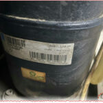
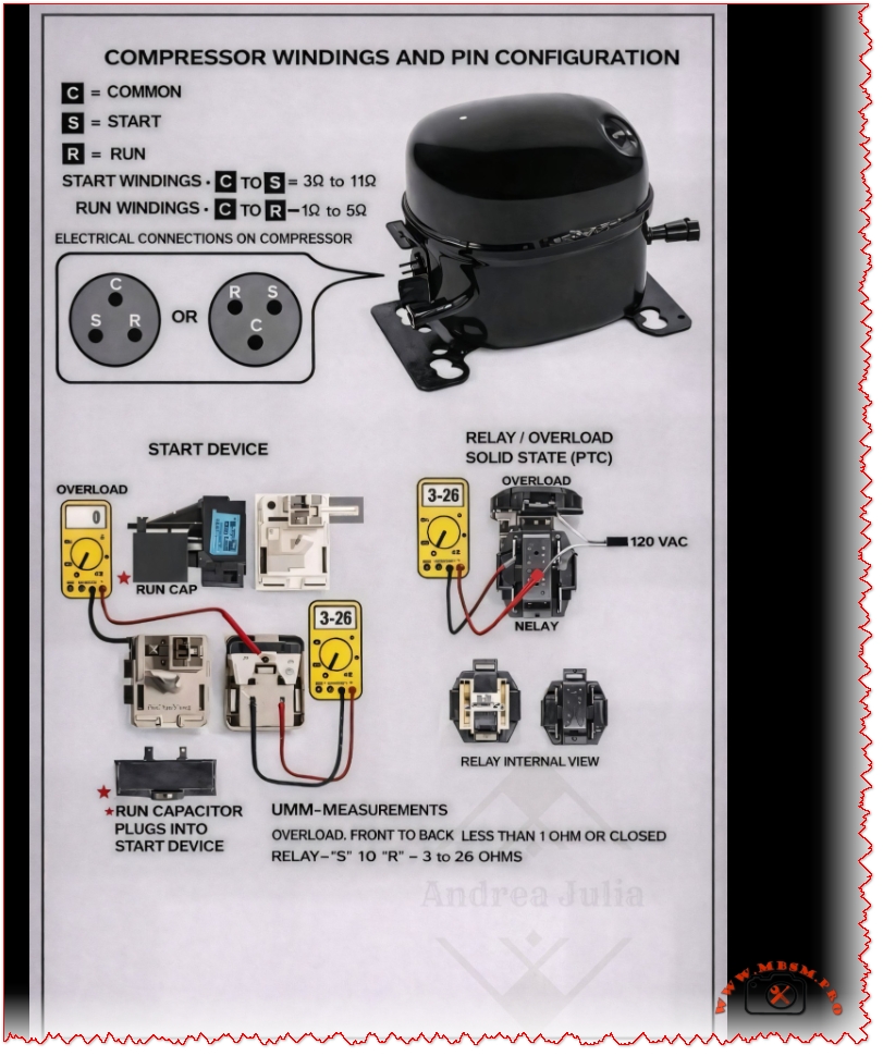
Compressor windings, terminal pin configuration, and the start components used in a refrigerator or air-conditioning compressor.
1. Compressor Windings and Terminals
A single-phase compressor has three terminals:
• C (Common)
• S (Start)
• R (Run)
These three pins can be arranged in different physical positions, but their electrical function is the same.
Winding Resistance Values (Typical)
Measured using a multimeter (Ohms Ω):
• C to S (Start winding): 3 Ω – 11 Ω
• C to R (Run winding): 1 Ω – 5 Ω
• S to R = Start + Run (highest resistance)![]() The Start winding always has higher resistance than the Run winding.
The Start winding always has higher resistance than the Run winding.
2. Electrical Connection on the Compressor
The diagram shows two possible layouts of the compressor pins.
Even if the position changes, the labels C, S, and R must be identified correctly before wiring.
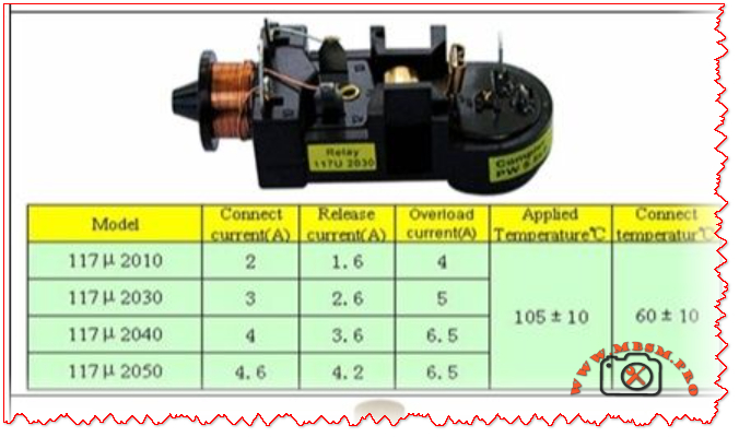
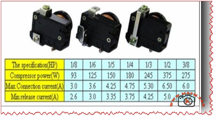
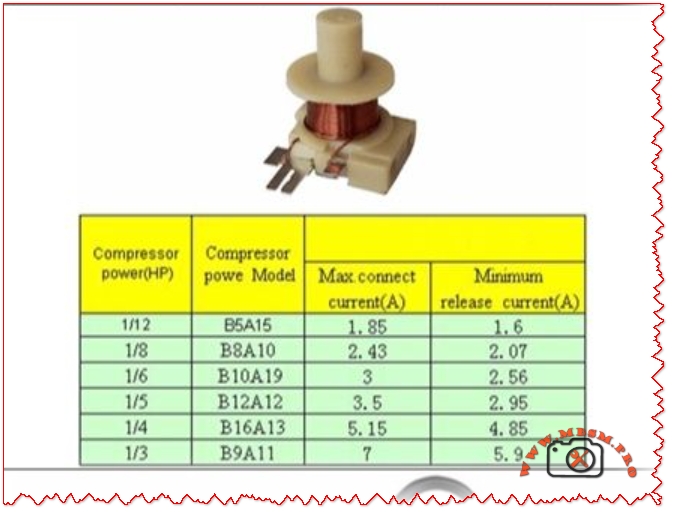
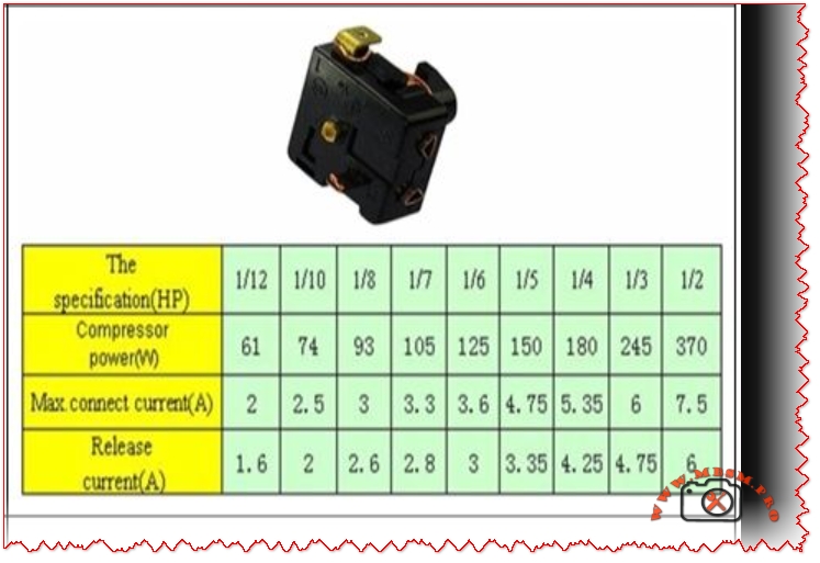
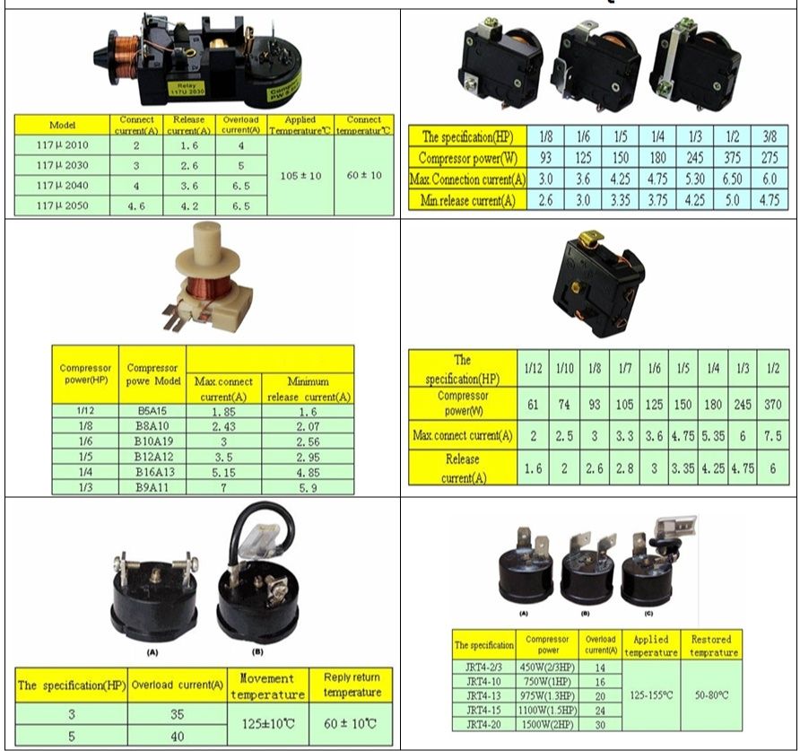
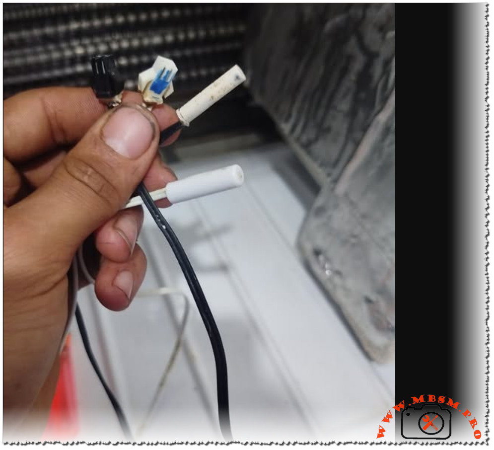
3. Start Device Assembly
The start system usually consists of:
• PTC Relay (Solid State Relay)
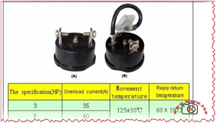
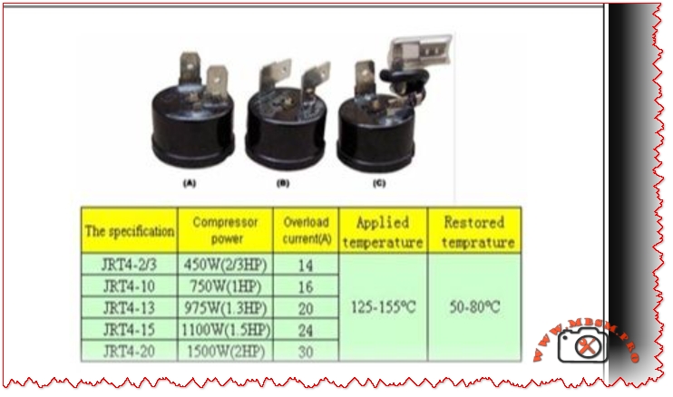
• Overload Protector
• Run Capacitor (if used)
Functions:
• PTC Relay:
– Temporarily connects the Start winding during startup.
– Disconnects it automatically once the compressor is running.
• Overload Protector:
– Protects the compressor from overheating or overcurrent.
– Opens the circuit if temperature or current is too high.
• Run Capacitor (optional on some models):
– Improves efficiency and torque during operation.
4. Multimeter Testing (Shown in Image)
Overload Test:
• Measure front to back
• Reading should be less than 1 Ω (closed circuit)
Relay Test:
• Measure between S and R
• Normal reading: 3 Ω – 26 Ω
Abnormal readings indicate a faulty relay or overload.
5. Power Supply
• The diagram shows 120 VAC input going through:
– Overload → Relay → Compressor terminals
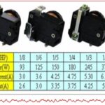
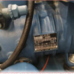
6. Internal Relay View
The bottom-right images show the internal structure of the relay, helping identify contacts and working condition.
See less