HITACHI FL20S88NAA Compressor
HITACHI FL20S88NAA Compressor Specifications: Complete Technical Guide for Sharp Refrigerators with HFC-134a R134a 220-240V 50Hz LBP
Comprehensive technical documentation on the HITACHI FL20S88NAA 0.75 HP refrigeration compressor and its integration in the Sharp SJ-PT73R-HS3 refrigerator-freezer unit. This professional guide covers compressor specifications, operating principles, performance comparisons, pressure classifications, and maintenance essentials for HVAC and refrigeration professionals.
Understanding the HITACHI FL20S88NAA Compressor: Core Specifications and Technical Characteristics
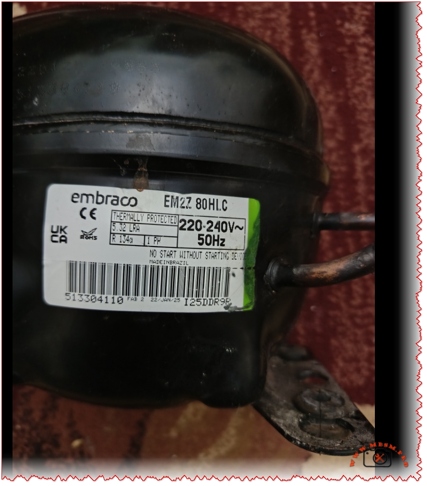
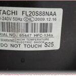
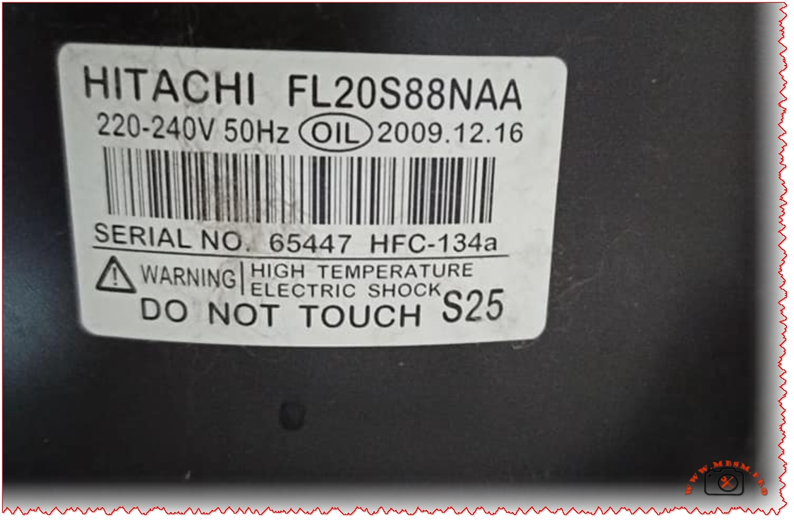
The HITACHI FL20S88NAA represents a critical component in small to medium-capacity refrigeration systems, specifically engineered for household refrigerator-freezer applications. This hermetic, scroll-based compressor operates on the low back pressure (LBP) principle, making it ideal for maintaining temperature ranges between −30°C and −10°C—the optimal zone for freezer compartments with secondary refrigeration cycles for fresh food storage. Manufactured on December 16, 2009, and bearing serial number 65447, this compressor demonstrates the robust engineering standards that established HITACHI’s reputation in refrigeration technology across the Asian and European markets.
The FL20S88NAA designation itself contains critical encoded information for technicians and engineers. The “FL” prefix indicates the Rotary Scroll Compressor Series, while “20” refers to the approximate displacement volume of 20.6 cubic centimeters per revolution. This displacement capacity, combined with 50Hz operation at 220-240V single-phase input, produces a rated cooling capacity of approximately 256 watts under ASHRAE test conditions—a specification that aligns with the energy demands of mid-size refrigerators ranging from 550 to 700 liters gross volume.
The compressor utilizes HFC-134a (R134a) refrigerant, a hydrofluorocarbon that has been the industry standard for household refrigeration since the phase-out of CFC-12 under the Montreal Protocol. The 110-gram charge specified for the Sharp SJ-PT73R-HS3 unit represents a carefully calibrated mass that balances system efficiency with environmental responsibility—HFC-134a has zero ozone depletion potential while maintaining favorable thermodynamic properties for small-scale refrigeration applications.
Pressure Classification and Operating Principles: LBP vs. Other Pressure Categories
The LBP (Low Back Pressure) designation distinguishes the FL20S88NAA from its medium back pressure (MBP) and high back pressure (HBP) counterparts, a classification system that directly reflects the compressor’s evaporating temperature operational range and intended application environment. Understanding this distinction is essential for proper compressor selection, replacement procedures, and system diagnostics.
Low Back Pressure (LBP) compressors like the FL20S88NAA are optimized for evaporating temperatures typically ranging from −10°C down to −35°C or lower, making them the standard choice for deep freezers, freezer compartments in refrigerators, and preservation units where sustained low temperatures are required. These compressors operate efficiently when the suction-side pressure remains low, which occurs naturally when the evaporator temperature is substantially below the ambient cooling environment.
| Pressure Classification | Evaporating Temperature Range | Typical Applications | Pressure Characteristics |
|---|---|---|---|
| LBP (Low Back Pressure) | −35°C to −10°C | Freezers, freezer compartments, preservation cabinets | Lower suction pressure, higher compression ratio |
| MBP (Medium Back Pressure) | −20°C to 0°C | Beverage coolers, cold display cabinets, milk coolers | Moderate suction pressure |
| HBP (High Back Pressure) | −5°C to +15°C | Room coolers, dehumidifiers, warmer applications | Higher suction pressure, lower compression ratio |
The compression ratio—the mathematical relationship between discharge pressure and suction pressure—becomes critically important when analyzing LBP versus MBP performance. The FL20S88NAA’s LBP optimization means it achieves maximum volumetric efficiency when operating across the wider pressure differential inherent in freezer systems, but attempting to operate this same compressor in an MBP application (such as a beverage cooler) would result in reduced cooling capacity, potential motor overheating, and shortened service life.
Electrical Specifications and Motor Design: RSIR Starting Method
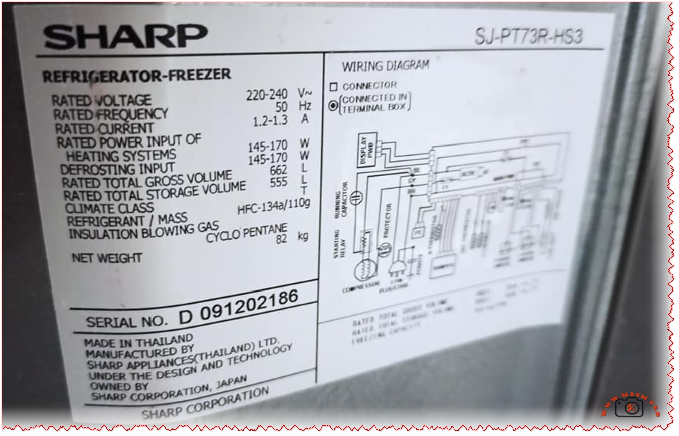
The electrical configuration of the FL20S88NAA incorporates the RSIR (Resistance Start, Induction Run) starting method—a proven design approach that uses the compressor motor’s run capacitor combined with a starting relay to achieve reliable cold starts without requiring additional starting capacitor hardware. This single-phase motor configuration accepts 220-240V at 50Hz frequency, with a rated current draw of approximately 1.2-1.3A during normal operation, producing a motor input of 145-170 watts.
The RSIR designation indicates that the compressor motor windings are designed with intentional resistance differential between the start and run coils, creating the phase shift necessary to produce rotating magnetic fields during the initial acceleration phase. Once the motor reaches approximately 75% of its synchronous speed, the starting relay mechanism automatically disconnects the start coil circuit, and the motor continues operating on the run coil alone—a configuration offering several advantages over alternative starting methods:
Advantages of RSIR Design:
- Simplified Control Circuitry: Eliminates the need for dedicated starting capacitors, reducing component count and complexity
- Reliable Cold Starts: Provides adequate starting torque even after extended shutdown periods when gas pressures have equalized
- Extended Motor Life: The reduced electrical stress during startup contributes to longer operational life compared to capacitor-start designs
- Cost Effectiveness: Lower manufacturing complexity translates to reduced acquisition costs
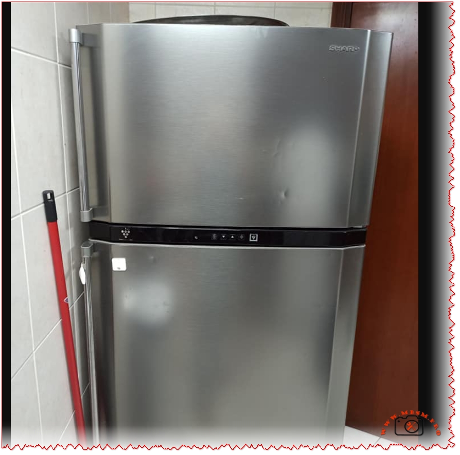
The Sharp SJ-PT73R-HS3 Refrigerator: Integration and Performance Specifications
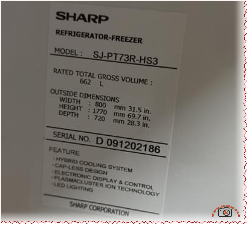
The SHARP SJ-PT73R-HS3 represents a mid-range, dual-chamber refrigerator-freezer unit engineered around the FL20S88NAA compressor as its primary cooling agent. With a gross storage volume of 662 liters and net capacity of 555 liters, this model exemplifies the contemporary approach to household refrigeration, combining traditional vapor-compression cooling technology with advanced supplementary systems for enhanced freshness retention.
The refrigerator’s physical footprint—800mm width, 1770mm height, and 720mm depth—accommodates standard kitchen layouts while maximizing internal storage efficiency through the Hybrid Cooling System. This technology employs an aluminum panel cooled to approximately 0°C, which acts as an intermediary heat sink. Rather than exposing food directly to rapid cold air circulation (which causes dehydration), the Hybrid Cooling System distributes temperature-controlled air more gradually across all compartments, maintaining humidity levels while preventing moisture loss from produce and fresh items.
The electrical specifications indicate a refrigerant charge of 110 grams HFC-134a and insulation blowing gas consisting of cyclo pentane (a hydrocarbon substitute for CFCs). The unit’s net weight of 82 kilograms reflects substantial internal copper piping, aluminum evaporator surfaces, and the insulation foam layer manufactured with flammable blowing agents—an environmental trade-off that reduces global warming potential while introducing manageable thermal stability requirements.
Refrigerant Properties and System Thermodynamics: HFC-134a Characteristics
HFC-134a (Hydrofluorocarbon-134a, also marketed as Freon™ 134a) possesses specific thermodynamic properties that make it uniquely suited for small hermetic refrigeration systems like the FL20S88NAA. With a boiling point of −26.06°C at one atmosphere and a critical temperature of 101.08°C, HFC-134a occupies a favorable operating envelope for household refrigeration where evaporator temperatures range from −30°C to +5°C and condenser temperatures typically reach 40−60°C.
The refrigerant’s molecular weight of 102.03 g/mol and critical pressure of 4060.3 kPa absolute influence the pressure-temperature relationships critical for technician diagnostics. At an evaporating temperature of −23.3°C (ASHRAE rating condition), HFC-134a exhibits a saturation pressure of approximately 1.0 bar absolute, while at a condensing temperature of 54.4°C (130°F), the saturation pressure rises to approximately 10.6 bar absolute—a pressure ratio of roughly 10:1 that the FL20S88NAA’s displacement and motor design accommodate efficiently.
The solubility of HFC-134a in mineral oil adds complexity to compressor oil selection and system lubrication strategy. The refrigerant dissolves in the compressor’s mineral oil lubricant to varying degrees depending on temperature and pressure conditions. This miscibility is essential for proper motor cooling and bearing lubrication but requires careful attention during system service—oil contamination with air or moisture accelerates acid formation, potentially damaging motor insulation and compressor valve surfaces.
Displacement Volume and Cooling Capacity Performance Analysis
The FL20S88NAA’s 20.6 cm³ displacement per revolution, operating at 50Hz (3000 RPM nominal synchronous speed, typically 2800-2900 RPM actual), theoretically moves approximately 617 cm³ (0.617 liters) of refrigerant gas per minute under full-speed operation. However, actual volumetric efficiency—the percentage of theoretical displacement that translates to useful refrigerant circulation—typically ranges from 65−85% depending on system operating conditions, suction line pressure, and compressor wear characteristics.
The 256-watt cooling capacity specification deserves careful interpretation. This measurement represents the heat removal rate (in joules per second) achieved under standardized ASHRAE test conditions: evaporating temperature of −23.3°C, condensing temperature of 54.4°C, and subcooled liquid entering the expansion device. This cooling capacity represents the actual useful heat transfer occurring at the evaporator surface, not the total energy input to the system. The relationship between cooling capacity, displacement, and power input defines the Coefficient of Performance (COP)—a unitless metric expressing system efficiency:
COP = Cooling Capacity (W) / Compressor Power Input (W)
For the FL20S88NAA operating near design conditions:
COP ≈ 256 W / 160 W ≈ 1.6
This 1.6 COP indicates that for every watt of electrical energy supplied to the motor, the system removes 1.6 watts of heat from the refrigerated space—a reasonable efficiency level for small hermetic compressors operating under typical household refrigeration loads.
Starting Method, Relay Operation, and Control System Integration
The RSIR (Resistance Start, Induction Run) starting methodology employed by the FL20S88NAA requires careful coordination between the motor windings, starting relay, and compressor discharge pressure characteristics. During the startup sequence—the critical 0−3 second period when the motor must accelerate from zero to approximately 75% synchronous speed—the starting relay circuit permits current through both main and auxiliary motor windings, creating the requisite rotating magnetic field.
As motor speed increases, back EMF (electromotive force) builds in the run winding. When back EMF reaches approximately 75% of applied voltage, the pressure equalization mechanism integrated into the compressor discharge line equalizes internal pressures, reducing the starting torque requirement. Simultaneously, the starting relay detects this speed increase through a combination of current sensing and mechanical timing, automatically opening the starting circuit.
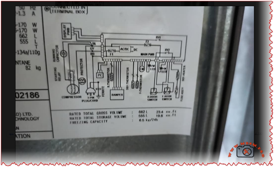
The Sharp SJ-PT73R-HS3’s electronic control system monitors refrigerator and freezer compartment temperatures through thermistor sensors, determining when to activate the compressor. A typical refrigeration cycle operates on an ON/OFF basis: when freezer temperature rises above the setpoint (typically −18°C), the thermostat closes a relay contact, energizing the compressor motor. The motor runs continuously until evaporator temperature drops to satisfy the freezer setpoint, at which point the thermostat opens the relay, stopping the compressor. This simple but effective control strategy suits the thermal mass and insulation characteristics of large household refrigerators.
Comparison with Modern Inverter Compressors and Energy Efficiency Implications
Contemporary refrigerator designs increasingly incorporate inverter compressors—variable-speed motors controlled by electronic inverter drives that adjust compressor speed continuously based on cooling demand. Sharp’s J-Tech Inverter technology, featured in their premium refrigerator models, offers substantial energy savings compared to fixed-speed designs like those utilizing the FL20S88NAA.
| Performance Parameter | Fixed-Speed (FL20S88NAA Type) | Inverter-Based System | Improvement |
|---|---|---|---|
| Energy Consumption | 100% (baseline) | 60−70% | 30−40% reduction |
| Noise Level | 100% (baseline) | ~50% | 50% noise reduction |
| Vibration | 100% (baseline) | ~70% | 30% vibration reduction |
| Temperature Stability | ±3−5°C variance | ±0.5−1°C variance | Significantly improved |
| Compressor On/Off Cycles | ~8−15 per hour | ~50+ per hour (variable speed) | More stable operation |
The energy efficiency advantage stems from compressor speed modulation. Fixed-speed compressors like the FL20S88NAA operate in a binary mode: either running at full displacement (consuming maximum power) or completely stopped. During partial-load conditions—when the refrigerator’s cooling requirement is less than the compressor’s full capacity—the system cycles on and off frequently, wasting energy during starting transients and experiencing temperature overshoot/undershoot between cycles.
Inverter systems address this through continuous variable-speed operation. When cooling demand decreases, the inverter electronics progressively reduce motor frequency and voltage, allowing the compressor to operate at lower displacement rates. This eliminates the energy waste from repeated start/stop cycles and maintains more stable compartment temperatures. Testing by Sharp indicates approximately 40% faster ice cube formation and 10% additional energy savings in Eco Mode compared to conventional fixed-speed designs.
Oil Charge Requirements and Lubrication Considerations
The FL20S88NAA specification calls for precisely 220 grams of mineral-based compressor oil—a critical parameter that directly affects motor cooling, bearing lubrication, and long-term compressor reliability. Insufficient oil reduces bearing film thickness and motor cooling effectiveness, while excess oil impairs heat transfer at the motor windings and can damage the expansion valve through oil slugging (liquid oil being pumped into the evaporator discharge line).
The oil selection process involves considering the refrigerant miscibility characteristics. HFC-134a systems typically employ mineral oils with kinematic viscosity around 32 cSt at 40°C, a standard that balances viscous film strength at bearing surfaces with the reduced viscosity that occurs when refrigerant dissolves in the oil during system operation. At typical operating temperatures (motor discharge reaching 80−100°C), the combined refrigerant-oil mixture maintains adequate viscosity for bearing protection while allowing efficient heat transfer away from motor windings.
Maintenance, Diagnostics, and Service Considerations
Professional HVAC technicians servicing the Sharp SJ-PT73R-HS3 or similar systems using the FL20S88NAA require specific diagnostic approaches. Key parameters to monitor include:
Suction Pressure Monitoring: At the compressor inlet, steady-state suction pressure should reflect the evaporating temperature. For −23.3°C ASHRAE conditions, expect approximately 1.0 bar absolute. Abnormally high suction pressure suggests restricted refrigerant metering (plugged expansion valve), while low suction pressure indicates insufficient evaporator heat absorption or refrigerant charge loss.
Discharge Pressure Analysis: Condensing temperature directly influences discharge pressure. At typical ambient conditions (27°C kitchen temperature), expect discharge pressures of 8−12 bar absolute. Excessively high discharge pressure (>14 bar) indicates condenser fouling, non-condensables in the refrigerant circuit, or restriction in the discharge line. Abnormally low discharge pressure suggests superheated refrigerant or loss of refrigerant charge.
Motor Current Signature Analysis: The FL20S88NAA’s rated run current of 1.2−1.3A provides a baseline for condition assessment. Elevated current draw (>1.5A sustained) indicates either elevated system pressures (condenser dirty, high ambient temperature) or motor winding degradation. Diminished current draw (<1.0A) suggests insufficient load, possibly from low system pressures from refrigerant loss.
Liquid Line Temperature: Ideally, the high-pressure liquid exiting the condenser should be 5−10°C above ambient. This “subcooling” indicates proper refrigerant charge levels and condenser performance. Insufficient subcooling suggests low charge or poor condenser air flow; excessive subcooling (>15°C above ambient) may indicate excess charge or expansion valve malfunction.
Compatibility, Retrofitting, and Replacement Considerations
The FL20S88NAA occupies a specific application niche that has remained largely stable since its introduction in 2009, reflecting the standardization of household refrigerator designs. When replacement becomes necessary—typically after 15−20 years of operation or following mechanical failure—technicians must carefully assess compatible alternatives.
Direct Replacement Options: The HITACHI FL20H88-TAA represents a direct successor, offering identical displacement but enhanced efficiency. The H-series designation indicates “Improved” performance characteristics.
HFC-134a Retrofitting: Any replacement compressor must be HFC-134a compatible. Retrofitting from older CFC-12 or HCFC-22 systems to R134a requires not only compressor replacement but also expansion valve adjustment (R134a typically requires finer orifice sizing), lubricant conversion (synthetic polyol ester oils for R134a vs. mineral oils for CFC-12), and sometimes condenser enhancement due to R134a’s different heat transfer characteristics.
Cross-Reference Challenges: Different manufacturers encode compressor specifications differently. A technician replacing the FL20S88NAA might encounter GMCC, Copeland, or Tecumseh alternatives with fundamentally equivalent displacement and pressure ratings. Success requires consulting manufacturer’s cross-reference tables and verifying that replacement units operate at 220-240V/50Hz and suit LBP applications.
Conclusion: Integration of Compressor Technology in Modern Refrigerator Systems
The HITACHI FL20S88NAA compressor embedded within the Sharp SJ-PT73R-HS3 refrigerator-freezer unit exemplifies the technical sophistication underlying everyday household appliances. This 0.75-horsepower hermetic scroll compressor, optimized for 220-240V/50Hz operation with HFC-134a refrigerant and LBP pressure characteristics, delivers approximately 256 watts of cooling capacity while consuming just 160 watts of electrical power—a 1.6 COP that reflects decades of incremental engineering refinement.
The integration of the Hybrid Cooling System, electronic temperature control, and RSIR-method starting represents a balanced approach to refrigerant-based heat transfer, prioritizing reliability and simplicity over the variable-speed sophistication now becoming standard in premium models. For regions utilizing 50Hz electrical infrastructure and requiring robust, serviceable refrigeration systems, the specifications outlined herein provide both immediate diagnostic guidance and long-term maintenance planning tools.
As the refrigeration industry transitions toward next-generation compressor technologies—incorporating variable-speed inverter drives, alternative refrigerants such as HFO-1234yf and hydrofluoroolefins (HFOs) for reduced global warming potential, and AI-enabled predictive maintenance systems—the FL20S88NAA remains an instructive reference point for understanding the thermodynamic principles that continue to govern small-scale refrigeration applications worldwide.
SEO Optimization for WordPress/Yoast:
Focus Keyphrase (Maximum 191 characters):
HITACHI FL20S88NAA compressor 0.75 HP specifications HFC-134a R134a 220-240V 50Hz LBP refrigerator
SEO Title (Optimal length 50-60 characters):
HITACHI FL20S88NAA Compressor: Complete Technical Specifications Guide for HFC-134a Refrigerators
Meta Description (Optimal length 155-160 characters):
Professional guide to HITACHI FL20S88NAA 0.75 HP refrigerator compressor. Specifications, LBP pressure classification, HFC-134a refrigerant, operating principles for technicians.
Slug:hitachi-fl20s88naa-compressor-specifications-guide
Tags:
HITACHI, FL20S88NAA, Compressor, Refrigerator, HFC-134a, R134a, 220-240V, 50Hz, LBP, Cooling Capacity, SHARP, SJ-PT73R-HS3, Hybrid Cooling, Mbsmgroup, Mbsm.pro, mbsmpro.com, mbsm, Technical Specifications, HVAC, Refrigeration, RSIR Starting Method
Excerpt (First 55 words):
The HITACHI FL20S88NAA 0.75 HP hermetic scroll compressor delivers 256W cooling capacity at 50Hz, utilizing HFC-134a refrigerant for household refrigerator-freezer applications. This LBP-classified unit operates reliably at 220-240V with RSIR starting method, integrated into Sharp’s SJ-PT73R-HS3 model offering 662-liter gross capacity with Hybrid Cooling System and Plasmacluster technology.