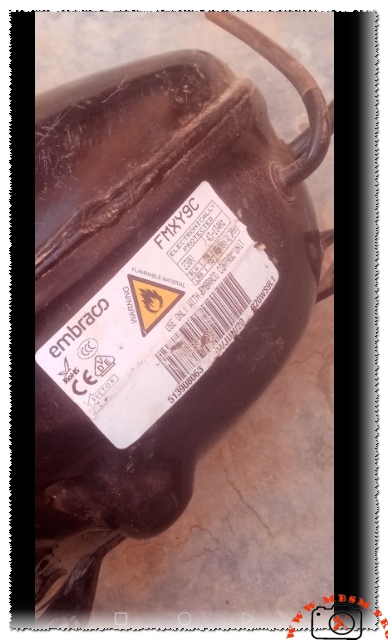
Mbsmpro.com, Compressor, FMXY9C, 1/5 hp, Inverter, Fullmotion, R600a, 230V 43-134Hz, LBP, Variable Speed, High Efficiency

Over my decades in the refrigeration trenches, I have seen the industry shift from robust, “clunky” fixed-speed pumps to the sophisticated whispering of variable-capacity units. When I walk up to a modern high-end residential refrigerator and hear that signature high-pitched ramp-up, I know I am likely dealing with an Embraco FMXY9C. These “Fullmotion” inverter compressors are the gold standard for energy efficiency today, but for many technicians, they remain a “black box” of mystery. If the cabinet is warm and you don’t hear that specific harmonic hum, you are likely looking at a complex dance between the inverter control board and the compressor windings.
Mastering the FMXY9C: The Engineer’s Technical Breakdown
The FMXY9C is not your grandfather’s compressor. As a Senior Engineer, I categorize this as a Variable Capacity Compressor (VCC). Unlike standard units that are either “On” or “Off,” this unit varies its speed between 43Hz and 134Hz. This allows the refrigerator to maintain a near-constant temperature without the massive energy spikes associated with traditional startup cycles.
| Feature | Technical Specification |
| Model | FMXY9C |
| Utilisation (MBP/HBP/LBP) | LBP (Low Back Pressure) |
| Domaine (Freezing/Cooling) | Domestic Freezing & Cooling |
| Oil Type and Quantity | Alkylbenzene (AB) / 180 ml |
| Horsepower (HP) | 1/5 HP (Equivalent at 3000 RPM) |
| Refrigerant Type | R600a (Isobutane) |
| Power Supply | 230V (3-Phase output from Inverter) |
| Frequency Range | 43 Hz to 134 Hz |
| Cooling Capacity (BTU/h) | 280 – 850 BTU/h (Variable) |
| Motor Type | BPM (Brushless Permanent Magnet) |
| Displacement | 8.74 cm³ |
| Winding Material | Copper |
| Pressure Charge (Low Side) | 0.5 to 1.5 psi (Running) |
| Capillary Tube Size | 0.026″ or 0.031″ (Application dependent) |
| Refrigerator Compatibility | High-end Samsung, LG, Whirlpool, Bosch |
| Temperature Function | -35°C to -10°C (-31°F to 14°F) |
| Fan Requirement | No (Static) or Yes (Enclosed cabinet) |
| Commercial Application | No (Domestic Only) |
| Amperage (Running) | 0.4A to 1.5A (Varies by speed) |
| LRA (Locked Rotor Amps) | N/A (Electronically limited) |
| Relay Type | None (Direct Inverter Control) |
| Capacitor | None (Handled by Inverter Board) |
The Engineer’s Secret: Diagnostic Logic for Inverter Systems
In my experience, the most common mistake field workers make is trying to “jump-start” this compressor directly from a wall outlet. Do not do this. You will instantly destroy the permanent magnet motor.
To diagnose a suspected FMXY9C failure, I follow this non-negotiable protocol:
- The Resistance Equilibrium: Disconnect the three-pin plug. Measure the resistance between all three pins (U, V, W). You should find near-identical readings (typically between 10 to 16 ohms depending on ambient temp). If one leg is “open” or significantly higher, the compressor is dead.
- The Inverter Signal Test: If the windings are balanced, the fault usually lies in the Embraco Control Unit. Check for the DC signal from the main logic board to the inverter. If the control board isn’t sending the “frequency command,” the compressor will never ramp up.
- The R600a Warning: This unit uses Isobutane. I always use a “No-Flame” approach (Locring or high-quality compression fittings) unless I have a fully purged environment. Isobutane is highly flammable, and safety is paramount when opening these systems.
Comparison: FMXY9C vs. Standard Fixed-Speed Compressors
| Feature | FMXY9C (Inverter) | EMY70CLP (Fixed Speed) |
| Energy Efficiency | Up to 40% Higher | Baseline |
| Temperature Swing | ±0.5°C | ±2.0°C |
| Noise Levels | 32-34 dBA | 38-42 dBA |
| Start-up Stress | Soft-start (Low stress) | High Torque (High stress) |
| Repair Complexity | High (Requires Electronics expertise) | Low (Mechanical/Relay focus) |
Professional Replacement Guide
When replacing an FMXY9C, you must stay within the inverter family. You cannot replace this with a standard R134a or R600a fixed-speed motor without replacing the entire control system of the refrigerator.
5 Direct Replacements (R600a Inverter Series)
- Embraco VEMZ 9C: The high-efficiency sibling, often a drop-in replacement.
- Secop (Danfoss) DLX7.0KK: A robust European alternative with similar displacement.
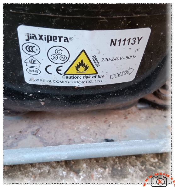
- Jiaxipera VNT1113Y: Frequently found in Chinese-manufactured high-end units.
- LG BSA075NHMV: Excellent reliability if mounting brackets align.
- Panasonic CBE series (Inverter): High-end Japanese alternative, very quiet.
5 Technical Alternatives (Different Gas/Type – Major Retrofit Required)
Warning: These require changing the control board and refrigerant circuit.
- Embraco VEGY 8H (R134a Inverter)
- Secop NLE15KTK (R290 – High efficiency but different pressure)
- Embraco FFI 10HBK (Fixed Speed R134a – Requires “Hardwire” hack)
- Tecumseh AE4440Y (Fixed Speed – Commercial grade)
- Danfoss FR10G (Heavy duty domestic)
Installation Masterclass & Pro Tips
- Vacuum Depth: Because R600a systems use very small charges (often less than 60g), moisture is a system-killer. I never stop until my micron gauge hits 250 microns.
- Filter Drier: Always use a drier specifically rated for R600a. Standard R134a driers may have desiccant that reacts poorly with isobutane over long periods.
- Charging Precision: Do not charge by pressure. You must use a digital scale accurate to 1 gram. A 5-gram error is enough to cause evaporator flood-back or poor cooling performance.
Question: Can I use a regular start relay on the FMXY9C for testing?
Answer: Absolutely not. This compressor requires a pulsed 3-phase signal generated by the inverter control unit. Applying 230V AC directly to the pins will result in permanent internal damage to the windings and the magnetic rotor.
Focus Keyphrase: Embraco FMXY9C Inverter Compressor Technical Guide
SEO Title: Mbsmpro.com, Compressor, FMXY9C, 1/5 hp, Inverter, R600a, 230V 43-134Hz
Meta Description: Expert guide for the Embraco FMXY9C Inverter Compressor. Technical specs, R600a safety, 1/5 HP equivalent, LBP diagnostic tips, and professional replacement options for HVAC technicians.
Slug: mbsmpro-embraco-fmxy9c-inverter-compressor-guide
Tags: Mbsmgroup, Mbsm.pro, mbsmpro.com, mbsm, FMXY9C, Embraco Fullmotion, R600a Inverter Compressor, 1/5 HP Compressor, VCC Troubleshooting, Refrigerator Repair, Secop DLX7.0KK, Jiaxipera VNT1113Y, LG BSA075NHMV, Inverter Board Diagnosis, HVAC Engineering, Refrigeration Pro Tips.
Excerpt: The Embraco FMXY9C is a high-efficiency inverter compressor designed for modern R600a refrigeration systems. Operating at variable speeds between 43Hz and 134Hz, this unit offers superior energy savings. This guide provides technical specifications, diagnostic protocols for technicians, and a list of compatible replacements to ensure a professional-grade repair every single time.