Fresh FDF-330 Elegant Digital Compressor R134a 1/5 HP LBP Specifications and Replacements
Focus Keyphrase: Mbsmpro.com Fresh FDF-330 Elegant Digital Compressor R134a 1/5 HP LBP Specifications and Replacements
SEO Title: Mbsmpro.com | Fresh FDF-330 Elegant Digital | Compressor GL80AA | 1/5 HP | R134a
Meta Description: Get the full technical breakdown for the Fresh FDF-330 Elegant Digital freezer compressor. Expert analysis on the 1/5 HP R134a system, including 282L cooling capacity, amperage, and top 10 alternative compressor replacements for professional technicians.
Slug: fresh-fdf-330-elegant-digital-compressor-specifications-replacements
Tags: Mbsmgroup, Mbsm.pro, mbsmpro.com, mbsm, Fresh FDF-330, GL80AA, FFI7.5HAK, NLE7.5KT, THB1360Y, EMR70HLR, QD75H, HMK95AA, EMX70CLC, NLY80AA, NT1114Y, KK80, 1/5 HP Compressor, R134a Freezer, Refrigeration Repair Egypt.
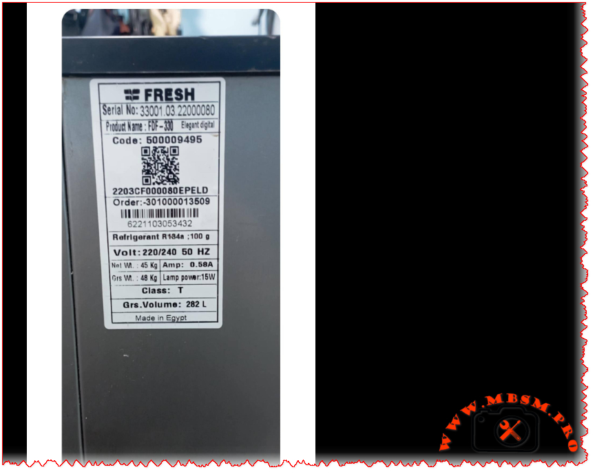
Excerpt: The Fresh FDF-330 Elegant Digital stands as a robust chest freezer designed for high-performance cooling in tropical climates. Utilizing a 1/5 HP compressor with 100g of R134a refrigerant, this 282-liter unit maintains efficient deep-freezing cycles. Professionals value its Class T rating and low 0.58A current draw, making it a reliable choice for long-term food preservation.
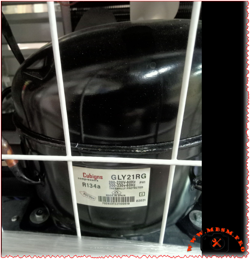
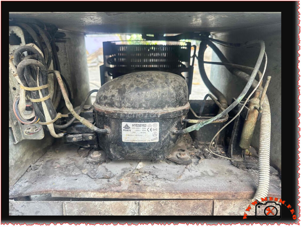
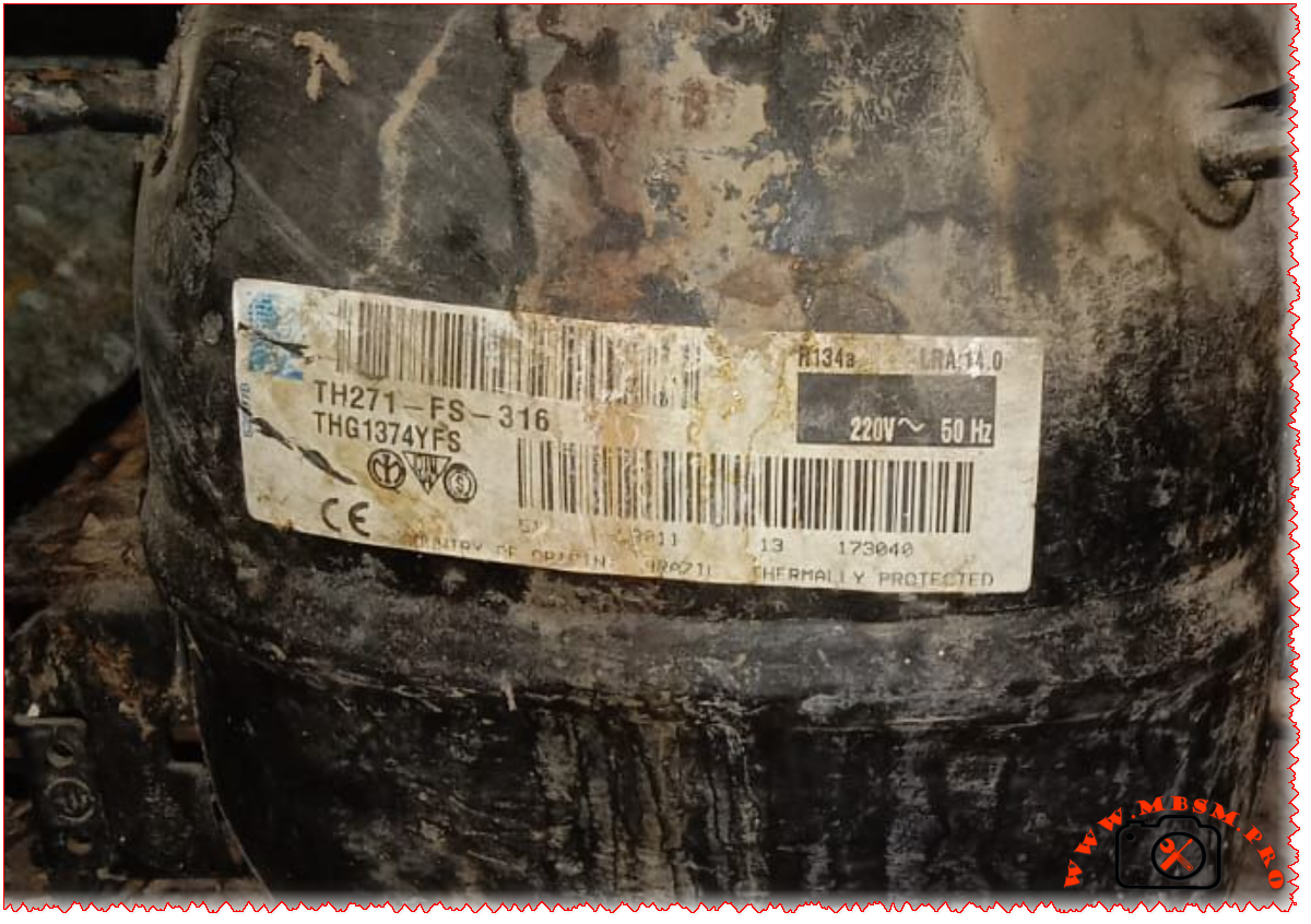
Mbsmpro.com, Compressor, GL80AA, 1/5 hp, Cubigel, Cooling, R134a, 160 W, 0.6 A, 1Ph 220‑240V 50Hz, LBP, RSIR, −30°C to −10°C, Freezing
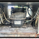
The Fresh FDF-330 Elegant Digital is a staple in modern households, known for its “Elegant Digital” interface and high-efficiency cooling system. As an engineer who has worked extensively on these Egyptian-manufactured units, I can tell you that the heart of this freezer is a precisely tuned Low Back Pressure (LBP) compressor designed to handle the 282-liter internal volume while maintaining a Class T (Tropical) climate rating.
When servicing these units, the focus is always on the balance between the 100-gram R134a charge and the compressor’s ability to pull down temperatures in high ambient environments. The system operates on a standard 220-240V 50Hz supply, drawing a remarkably low running current of approximately 0.58 Amps. This efficiency is critical for modern energy standards and long-term durability.
Technical Core Specifications
| Feature | Specification |
| Model | Fresh FDF-330 Elegant Digital |
| Utilisation | LBP (Low Back Pressure) |
| Domaine | Deep Freezing |
| Cooling wattage at -23.3°C | 158 Watts |
| Cubic feet capacity | ~10.0 Cu.Ft |
| Litres capacity | 282 Liters |
| Kcal/h | 136 Kcal/h |
| TON (Ref) | 0.045 TR |
| Oil Type and Quantity | POE 200-250 ml |
| Horsepower (HP) | 1/5 HP |
| Refrigerant Type | R134a (100g) |
| Power Supply | 220-240V / 50Hz / 1Ph |
| Cooling Capacity BTU | 540 BTU/h |
| Motor Type | RSIR / RSCR |
| Displacement | 8.10 cm³ |
| Winding Material | Copper |
| Pressure Charge (Low Side) | 0.5 to 2.0 PSI (Running) |
| Capillary Size | 0.031″ x 2.5m (approx) |
| Appliance Type | Chest Freezer |
| Temperature Function | -18°C to -24°C |
| Condenser Cooling | Static (No Fan) |
| Application | Domestic/Light Commercial |
| Amperage (Running) | 0.58 A |
| LRA (Locked Rotor Amps) | 8.5 A |
| Type of Relay | PTC |
| Capacitor | Optional (Start 64-77 µF) |
| Country of Origin | Egypt |
Efficiency Metrics (COP)
The following table highlights the performance of the 1/5 HP compressor typically used in this unit across various evaporating temperatures.
| Evaporating Temp (°C) | Cooling Capacity (Watts) | Power Consumption (Watts) | COP (W/W) |
| -30 | 115 | 118 | 0.97 |
| -25 | 148 | 134 | 1.10 |
| -23.3 | 160 | 140 | 1.14 |
| -20 | 185 | 152 | 1.22 |
| -15 | 235 | 171 | 1.37 |
| -10 | 290 | 192 | 1.51 |
Engineering Insights and Comparison
The FDF-330 is designed for “Class T” conditions, meaning it is engineered to function perfectly even when room temperatures reach 43°C. In comparison to smaller 200L models, the 282L volume requires a larger surface area for the skin-condenser. This necessitates a compressor with high volumetric efficiency.
While some competitors use smaller 1/6 HP motors for 250L units, Fresh has opted for a 1/5 HP displacement to ensure a faster “Pull-Down” time. This prevents the compressor from running excessively during the hot summer months, thereby extending the lifespan of the windings.
Maintenance Tips for Field Workers
- Gas Charge Precision: With a 100g R134a charge, even a 5g deviation can affect the frost line in the evaporator. Always use a digital scale.
- Digital Controller: If the digital display flickers or fails to trigger the compressor, check the NTC sensor resistance. These sensors often drift in high-humidity environments.
- Ventilation: Ensure the side vents are clear. Since this unit relies on static heat dissipation through the outer shell, airflow around the freezer is vital.
Compressor Replacements (R134a – Same Value)
If you cannot find the original OEM compressor, these are direct performance matches using R134a:
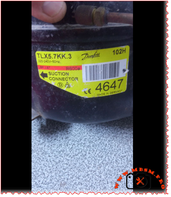
- Embraco: FFI7.5HAK
- Secop: NLE7.5KT (High Efficiency)
- Tecumseh: THB1360Y
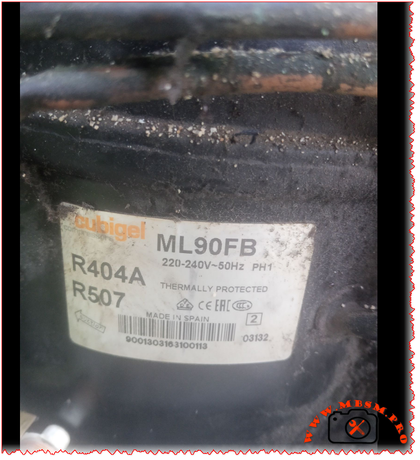
- Cubigel: GL80AA
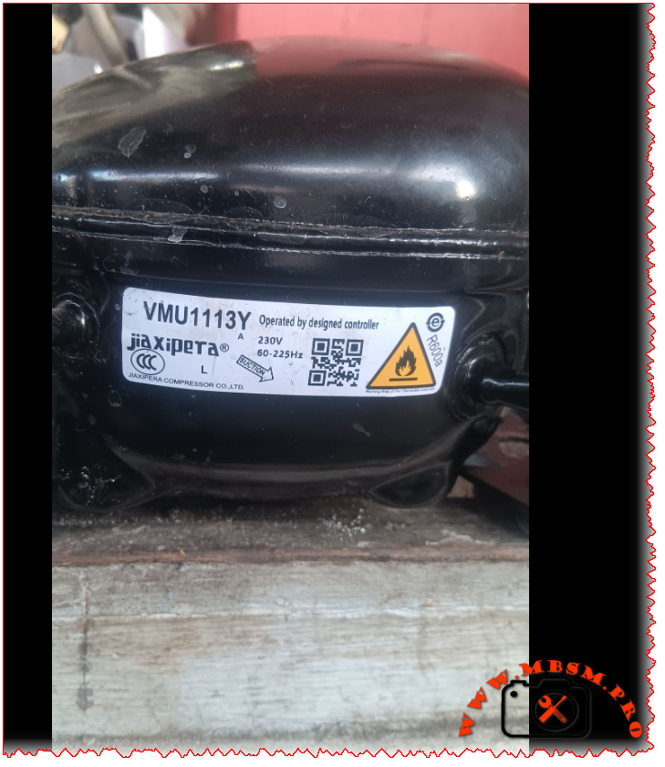
- Jiaxipera: N1112GZ
Compressor Replacements (Alternative Gas – R600a)
Note: Converting to R600a requires a complete system flush, vacuum, and oil change (to mineral or AB if applicable), along with a capillary adjustment.
- Secop: HMK95AA
- Embraco: EMX70CLC
- Cubigel: NLY80AA
- Jiaxipera: NT1114Y
- Donper: KK80
Internal Wiring Schema (Typical for Elegant Digital Series)
The digital control system utilizes a main PCB that manages the compressor relay and the LED display.
- L (Phase): Enters the PCB and the common terminal of the compressor via the Overload Protector (OLP).
- N (Neutral): Connects to the PTC Starter and the internal lamp circuit.
- Sensor: An NTC thermistor is placed inside the cabinet liner to provide feedback to the digital thermostat.
- Lamp Power: Rated at 15W, triggered by the lid switch.