Unionaire Super Tech / UFN‑230 No‑Frost upright freezer
Unionaire Super Tech 6‑Drawer Inverter No‑Frost Deep Freezer – Full English Review
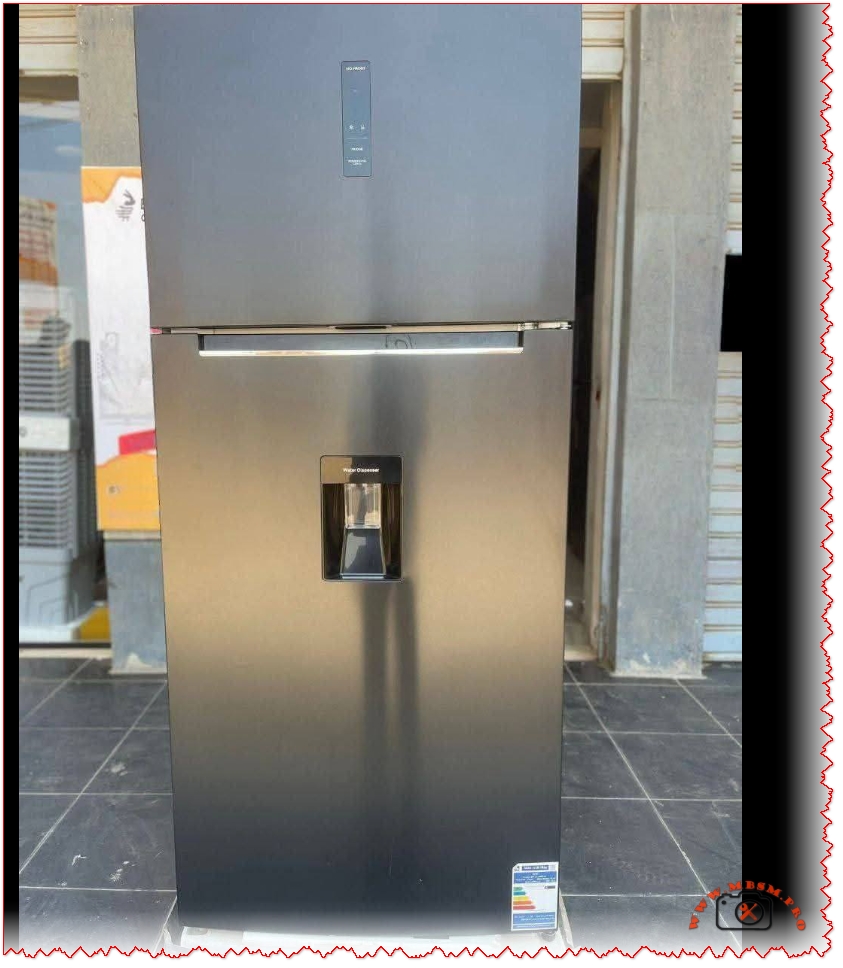
The Unionaire Super Tech upright deep freezer with 6 white drawers, inverter compressor, and steam No‑Frost system targets users who want modern design, digital control, and efficient freezing in a compact footprint. With its black glass door and touch digital display, it combines style and performance for households, mini‑markets, and premium kitchen projects such as those promoted by Mbsmgroup and its platforms.
Product overview
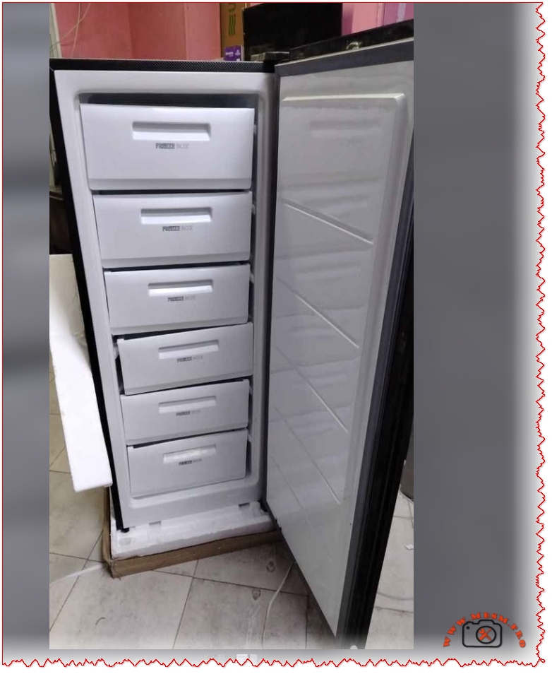
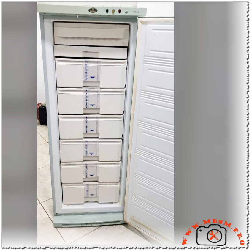
- Brand: Unionaire, upright deep freezer, around 230‑liter capacity with 6 sliding drawers for organized storage of meat, vegetables, and ready meals.
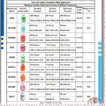
- Frost system: No‑Frost with forced air and automatic defrost, often marketed with steam‑assisted circulation to reduce ice formation on packages and drawer walls.
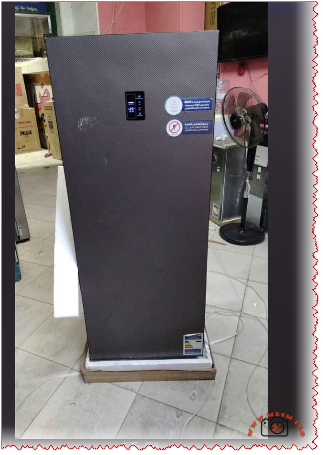
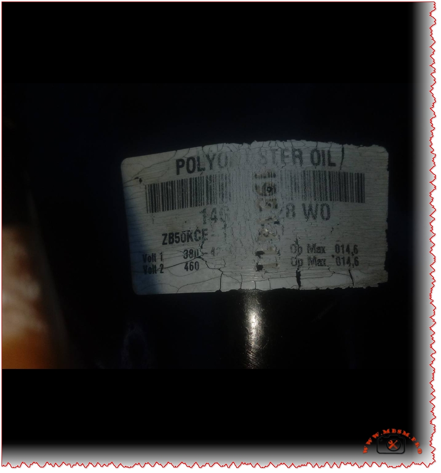
- Design: Black cabinet with glass-textured front door, similar to model codes UFN‑230LBG1A‑DH and UFN‑230EBG1A‑DH seen on regional e‑commerce sites.
Key features and technology
- Digital touch display on the front door allows precise temperature setting, fast‑freeze mode activation, and status monitoring without opening the door, reducing cold air loss.
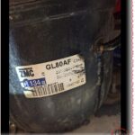
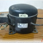
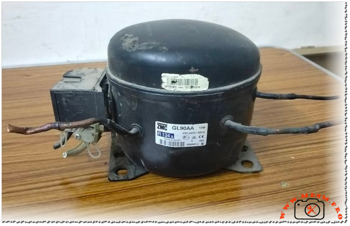
- Inverter‑type compressor (in newer Super Tech/UFN series) modulates speed according to load, improving energy efficiency and maintaining more stable internal temperatures compared with conventional on/off compressors.
- No‑Frost steam air‑flow distributes cooling evenly across all 6 drawers, limiting frost, minimizing freezer‑burn, and keeping textures closer to fresh when food is thawed.
Design, usability, and installation
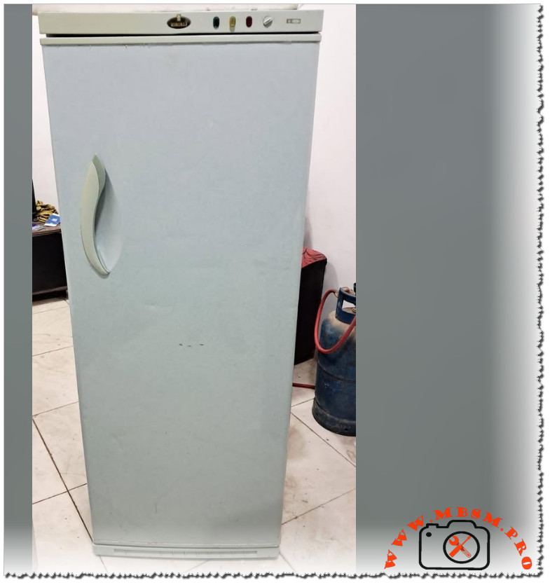
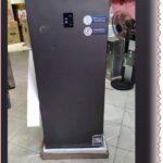
- The front door’s dark glass finish gives a premium look suitable for open kitchens, showrooms, or commercial corners, matching the aesthetic style seen in the provided photo.
- Vertical layout (approximate dimensions 157 × 60 × 69 cm for 230‑L models) makes it easier to place in tight spaces compared with bulky chest freezers, while interior LED lighting improves visibility in every drawer.
- Built‑in or recessed handle and adjustable feet help the cabinet sit stable even on slightly uneven tiles, something important in small shops or workshops where Mbsm.pro projects might install such units.
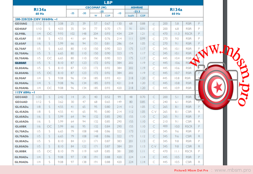
Technical specifications table
The following table summarizes typical specs for a Unionaire 6‑drawer No‑Frost digital deep freezer in the Super Tech / UFN‑230 series (values may vary slightly by sub‑model and country):
Ideal users and applications
- Families who need extra frozen storage without taking too much floor space, especially in apartments or duplex kitchens.
- Small grocery stores, butcher’s shops, pastry businesses, and workshop spaces promoted by Mbsmgroup and mbsmpro.com that require organized, quick‑access frozen storage with professional appearance.
- Users looking for low‑maintenance equipment; No‑Frost technology and digital alarms (door‑open / high‑temperature) reduce manual defrosting and help protect stored goods during busy operation.
Example product and catalog links
These links are suggested as reference resources and should be checked again during publishing for price and availability changes:
- Product pages with similar specs and real photos:
- General No‑Frost upright freezer user manual (PDF, safe to open) explaining digital control, alarms, and No‑Frost operation, suitable as a catalog‑style technical reference for readers: