Focus Keyphrase: Song Chuan 855AWP-1A-C2 12V DC 30A Power Relay Technical Specifications and HVAC Applications
SEO Title: Mbsm.pro, Song Chuan 855AWP-1A-C2, 12V DC, 30A, Power Relay, 240VAC, SPST-NO, High Current Control
Meta Description: Discover the technical depth of the Song Chuan 855AWP-1A-C2 30A power relay. This guide covers its 12V DC coil specifications, wiring schematics, and high-performance industrial applications.
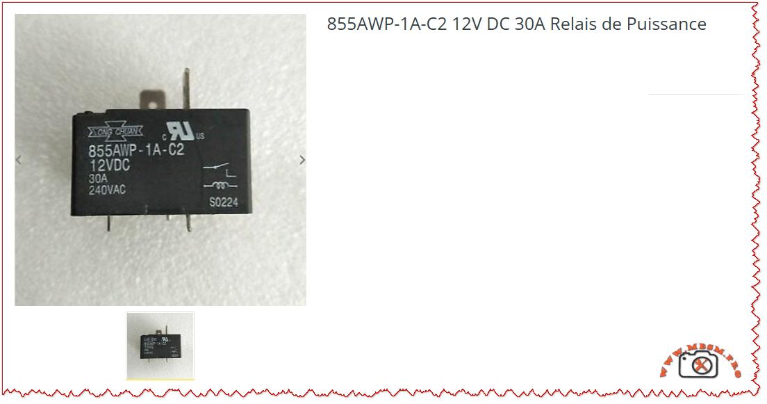
Excerpt: The Song Chuan 855AWP-1A-C2 is a high-performance 30A power relay designed for demanding electrical environments requiring robust 12V DC coil actuation. Primarily used in HVAC systems and heavy-duty industrial controls, this relay ensures reliable switching for loads up to 240VAC. This comprehensive guide provides essential technical insights, wiring configurations, and engineering advice for professionals.
Mbsmpro.com, Relay, Song Chuan, 855AWP-1A-C2, 12VDC, 30A, 240VAC, SPST-NO, Power Switching, HVAC, PCB Mount
In the realm of power electronics and industrial automation, the reliability of a switching component determines the longevity of the entire system. The Song Chuan 855AWP-1A-C2 stands as a benchmark for high-current PCB relays. Engineered for heavy-duty applications, this 30A power relay is a critical component for technicians and engineers dealing with heating, ventilation, air conditioning (HVAC), and automotive power management.
Technical Core and Engineering Excellence
The 855AWP series is specifically designed to handle high inrush currents. The “1A” designation indicates a Single Pole Single Throw – Normally Open (SPST-NO) contact arrangement. This means the circuit remains open until the 12V DC coil is energized, making it ideal for safety-critical “start-up” sequences in motors and compressors.
Key Technical Specifications
Feature
Specification Details
Manufacturer
Song Chuan (Xong Chuan)
Model Number
855AWP-1A-C2
Coil Voltage
12V DC
Contact Rating
30A @ 240V AC / 30A @ 30V DC
Contact Material
Silver Tin Oxide (AgSnO)
Configuration
1 Form A (Normally Open)
Termination
PCB Terminals with Quick Connect options
Operating Temperature
-40°C to +85°C
Dielectric Strength
2,500V AC (between coil and contacts)
Internal Schematic and Wiring Logic
Understanding the internal architecture is vital for proper PCB layout and field replacement. The 855AWP-1A-C2 features a simple but robust internal mechanism.
Coil Terminals (Control Side): These are the two pins that receive the 12V DC signal. When energized, the electromagnetic field pulls the armature to close the load circuit.
Load Terminals (Switch Side): These high-gauge terminals handle the 30A current. In most industrial applications, these are reinforced to prevent pitting and arcing.
<u>Expert Engineering Tip: When switching inductive loads (like a fan motor or a compressor), always use a flyback diode (e.g., 1N4007) across the DC coil to prevent back-EMF voltage spikes that could damage your control circuit.
Comparative Analysis: 30A vs. Standard 10A Relays
Field workers often ask if a standard relay can be substituted. The answer is usually no. The 855AWP-1A-C2 offers significantly different thermal management.
Parameter
Standard General Purpose Relay
Song Chuan 855AWP-1A-C2
Max Current
10A – 15A
30A
Contact Resistance
Moderate
Ultra-Low (to prevent heat)
Expected Life (Mechanical)
1,000,000 cycles
10,000,000 cycles
Typical Use
Light lighting/Signals
Compressors / Industrial Heaters
Housing
Standard Plastic
High-Temp Flux Tight (C2 Rating)
<u>Industrial Applications and Best Practices</u>
This relay is a “workhorse” found in various sectors. Its ability to switch high AC voltages with a low DC control signal makes it indispensable.
HVAC Systems: Controlling the outdoor condenser fan or the auxiliary heating element.
Power Supplies: Serving as the main disconnect for high-wattage UPS systems.
Industrial Automation: Acting as an interface between a low-power PLC output and a heavy motor starter.
Engineer’s Notice & Safety Advice
Avoid Overloading: While rated for 30A, running at the absolute limit for extended periods generates heat. For continuous loads (running 3+ hours), it is best practice to derate the relay to 24A (80% rule).
Check Soldering Integrity: Because this component carries high current, cold solder joints on a PCB can cause high resistance, leading to the relay melting the board itself. Use high-quality solder and ensure the traces are thick enough for 30A.
Environment: The “C2” rating indicates a flux-tight construction. However, in extremely dusty or humid environments, ensure the relay is housed in an appropriately rated NEMA enclosure.
Technical Resources and Data Links
For deep technical integration, we recommend reviewing the manufacturer’s original data sheets to verify timing diagrams and vibration resistance.
Official Catalog: Song Chuan Power Relay Series (855AWP PDF) (Note: External link, verify security upon clicking).
Cross-Reference Guide: Many technicians use Omron or TE Connectivity equivalents; however, the pinout of the 855AWP-1A-C2 is specific to its high-current capability.
Summary for Field Technicians: If you encounter a failure in a 12V control board managing a heavy compressor, the Song Chuan 855AWP-1A-C2 is your most reliable replacement choice. Its high dielectric strength and silver tin oxide contacts ensure that it will withstand the rigors of thousands of cycles without contact welding.
Mbsmpro.com, 78XX IC Family, Voltage Regulator, 7805, 7806, 7808, 7810, 7812, 7815, 7818, 7824, 5V, 6V, 12V, 15V, 24V, Linear Regulator, 1.5A, Thermal Protection
78XX Voltage Regulator Family: Complete Technical Guide & Applications
The 78XX series is one of the most widely adopted family of linear voltage regulators in electronics. These three-terminal ICs have powered countless consumer devices, industrial systems, and hobbyist projects since their introduction decades ago. From a simple 5V supply for microcontrollers to a robust 24V rail for automation, the 78XX family delivers fixed regulated voltage with minimal external components.
Whether you are designing a power supply, troubleshooting an embedded system, or maintaining legacy equipment, understanding the 78XX lineup—including the 7805, 7812, 7815, 7824, and their companions—is essential knowledge.
What Is the 78XX Voltage Regulator?
A voltage regulator is an electronic component that maintains a constant output voltage despite fluctuations in the input supply or changes in the load current. The 78XX family does this using a linear approach: it essentially acts as an intelligent resistor, dropping excess input voltage while supplying current at the regulated output level.
The “78XX” designation is a naming convention:
“78” indicates a positive voltage regulator (as opposed to 79XX for negative regulators).
“XX” is replaced by two digits representing the output voltage.
For example:
7805 = 5 V output
7812 = 12 V output
7824 = 24 V output
Complete 78XX Series Specifications & Voltage Breakdown
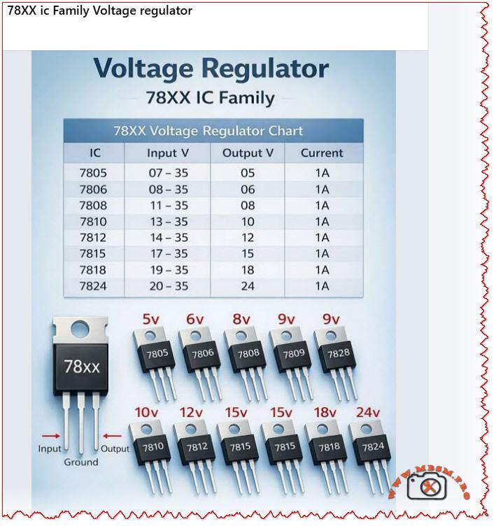
Below is the definitive reference table for the standard 78XX family, showing all available output voltages, input requirements, and current capability.
Output voltage range spans from 5 V to 24 V, covering nearly all common digital and analog supply voltages.
Input voltage must exceed output by at least 2–3 V (called the dropout voltage). For example, the 7805 requires minimum 7 V input to reliably deliver 5 V.
All variants provide up to 1.5 A continuous output current, making them suitable for moderate-power applications.
Larger output voltages (7815, 7824) allow higher maximum input voltage, useful in industrial environments.
78XX Internal Architecture & Operating Principle
The 78XX IC is a monolithic linear regulator, meaning all components are integrated on a single silicon die. Here is how it works internally:
Reference Voltage: An internal Zener diode generates a stable ~1.25 V reference.
Error Amplifier: Continuously compares the output voltage (via a voltage divider) against the reference.
Pass Transistor: A high-power Darlington transistor acts as a dynamic resistor, adjusting its resistance to maintain constant output voltage.
Feedback Loop: If output voltage rises, the error amp reduces pass transistor conductance (increases resistance). If output falls, it increases conductance. This negative feedback keeps output voltage rock-steady.
Built-in protection circuits:
Current Limiting: If load current exceeds ~2.2 A (typical), internal circuitry reduces the pass transistor bias, preventing damage.
Thermal Shutdown: If junction temperature exceeds ~125 °C, the regulator shuts down until cooling.
Short-Circuit Protection: If output is shorted to ground, the current limiter engages immediately.
Understanding the differences and similarities helps you choose the right device for your design.
78XX vs. 79XX (Negative Regulators)
Feature
78XX (Positive)
79XX (Negative)
Output polarity
Positive voltage
Negative voltage
Ground reference
Ground is 0 V
Ground is 0 V, output below ground
Typical use
Most digital logic, microcontroller power
Dual-supply op-amp circuits, symmetrical supplies
Pin configuration
IN / GND / OUT (left to right)
IN / GND / OUT (same order)
Examples
7805 (5V), 7812 (12V)
7905 (−5V), 7912 (−12V)
78XX vs. LM317 (Adjustable Regulator)
Aspect
78XX (Fixed)
LM317 (Adjustable)
Output voltage
Fixed (e.g., 5V, 12V)
User-adjustable via resistor divider
External parts
Minimal (2 capacitors)
More components (2 resistors + 2 capacitors)
Design flexibility
Low; choose IC for desired voltage
High; one IC, many output voltages
Design complexity
Beginner-friendly
Intermediate
Quiescent current
~3–5 mA
~3–5 mA
Max output current
1.5 A (1 A for 78L variant)
1.5 A (higher for LM350/LM338)
Physical Packages: TO-220 vs. TO-3
The 78XX is available in different packages, each suited to specific thermal and space constraints.
TO-220 Package (Most Common)
Dimensions: Roughly 10 mm × 5 mm × 5 mm tall.
Pins: Three leads (IN, GND, OUT).
Mounting: Can be soldered to PCB directly or mounted on a small heatsink.
Thermal resistance (package only): ~50–65 °C/W (case to ambient without heatsink).
Best for: General-purpose designs, moderate power dissipation (<2 W).
TO-3 Package (High-Power)
Dimensions: Larger, roughly 25 mm × 10 mm.
Mounting tab: Large metal collector tab for heatsink mounting (provides excellent thermal path).
Thermal resistance (with heatsink): ~1–2 °C/W (when mounted on large finned heatsink).
Best for: Industrial applications, sustained high current (approaching 1.5 A), harsh environments.
Field note: A 7805 in TO-220 without a heatsink can dissipate only ~500 mW before overheating. The same IC in TO-3 with a proper heatsink can safely handle 10+ watts of continuous dissipation.
Step-by-Step: How to Design a Simple 78XX Power Supply
Example: 12V / 1.5A Regulated Supply Using 7812
Components needed:
Component
Value
Purpose
Transformer (T1)
18 VAC, 2 A
Step down mains voltage
Bridge Rectifier (D1–D4)
1N4007 (or 1N4004) × 4, or bridge module
Convert AC to pulsating DC
Filter Capacitor (C1)
2200 µF, 35 V (electrolytic)
Smooth rectified voltage
Input Bypass (C2)
0.33 µF ceramic
Reduce high-frequency noise at 7812 input
Output Bypass (C3)
0.1 µF ceramic
Reduce output ripple
IC1
LM7812 (or 7812 variant)
Voltage regulator
Heatsink
Aluminum fin, ~1 K/W
Thermal management for 7812
Output LED (optional)
5 mm red LED + 1 kΩ resistor
Power indicator
Fuse (F1)
2 A slow-blow
Protection
Circuit Operation:
AC Input (18 VAC): From transformer secondary.
Rectification: Bridge diode converts AC to ~25 VDC (peak), with ripple.
Filtering: Large capacitor (2200 µF) smooths to ~20–22 VDC steady-state (ripple ~2–3 V).
Output: Clean 12 V can power logic, relays, or motors.
Thermal calculation:
Input: 20 V, Output: 12 V → Voltage drop = 8 V
Load current: 1 A (worst case)
Power dissipation in IC: P = (20 − 12) × 1 = 8 watts
Using a 1 °C/W heatsink: Temperature rise = 8 W × 1 °C/W = 8 °C
If ambient = 25 °C → Junction ≈ 33 °C ✓ (well below 125 °C limit)
Essential Capacitor Selection for 78XX Designs
Capacitors at the input and output are not optional—they are essential for stable, noise-free operation.
Input Bypass Capacitor (C_in)
Specification
Typical Value
Notes
Value
0.33 µF ceramic or polyester
Blocks high-frequency noise from upstream transformer/rectifier.
Voltage rating
At least 50 V (to handle max input voltage)
Safety margin is important.
Type
Ceramic (X7R dielectric preferred) or film (Mylar)
Avoid electrolytic here; ESR may be excessive.
Placement
Within 1 cm of 7805 input pin
Short leads reduce noise coupling.
Why: Without C_in, AC ripple from the rectifier can cause regulation errors and introduce noise into the output.
Output Bypass Capacitor (C_out)
Specification
Typical Value
Notes
Value
0.1–0.47 µF ceramic
Stabilizes 7805 against transient load changes.
Voltage rating
At least 25 V (output voltage + margin)
35 V ceramic is standard.
Type
Low-ESR ceramic (X7R, 100 nF–470 nF)
Electrolytic capacitors are NOT recommended; high ESR causes instability.
Placement
Within 1 cm of 7805 output pin, and load
Keeps parasitic inductance minimal.
Why: Output capacitor provides fast current during load transients (e.g., when a microcontroller suddenly draws peak current). Without it, output voltage sags momentarily, risking microcontroller brownout or data corruption.
Heat Dissipation & Thermal Design
The 78XX dissipates as much power as it must “drop” across its internal pass transistor. This heat must be conducted away, or the regulator will shut down.
Thermal Resistance Chain
textJunction Temperature (Tj)
        ↓
    ΔT_JC (junction to case)
        ↓
    ΔT_CS (case to sink)
        ↓
Heatsink Temperature (Th)
        ↓
    ΔT_SA (sink to ambient)
        ↓
Ambient Temperature (Ta)
Practical Example: 7812 Regulator in Hot Environment
Given:
Output voltage: 12 V
Input voltage: 24 V
Load current: 1 A
Ambient temperature: 45 °C (hot climate)
Maximum allowed junction temperature: 125 °C
Calculate:
Power dissipation: P = (V_in − V_out) × I = (24 − 12) × 1 = 12 watts
Thermal budget: ΔT_max = 125 − 45 = 80 °C
Required total thermal resistance: R_θ_total = ΔT / P = 80 / 12 ≈ 6.7 °C/W
Thermal path breakdown (TO-220 package):
Junction to case (R_θ_JC): ~5 °C/W (device dependent)
Case to sink (R_θ_CS): ~0.5 °C/W (with thermal grease on clean surface)
Remaining for sink: 6.7 − 5.5 = 1.2 °C/W
Heatsink requirement: Must be ≤1.2 °C/W to ambient.
A typical aluminum fin heatsink in still air provides ~2–3 °C/W.
A fan-cooled or liquid-cooled heatsink provides ~0.5–1 °C/W.
Conclusion: For 12 W dissipation in a 45 °C ambient, a small passive aluminum heatsink + forced-air fan is required to stay within safe temperature limits.
Comparison: 78XX vs. Modern Switching Regulators
The 78XX is old, but still relevant. Here is how it compares to modern alternatives:
When to use 78XX: Simple designs, low current (<500 mA), noise-sensitive analog circuits, hobby projects, rapid prototyping.
When to use switching regulators: Battery-powered equipment, space-constrained designs, high-power supplies (>5 W), efficiency-critical systems.
Real-World Applications of 78XX Regulators
1. Microcontroller Power Supply
A hobby project using an Arduino or PIC microcontroller typically uses a 7805 to supply clean 5V to the logic circuits and sensors.
Typical schematic:
Unregulated supply (9–12 V from USB or battery) → 7805 → Arduino (5V rail)
Minimal external components; occupies <1 cm² of PCB.
2. Industrial Motor Control Panel
A 7812 or 7815 provides the supply for PLC logic, relay drivers, and sensor inputs in an automated manufacturing system.
Design considerations:
Input derived from 24 VDC industrial bus.
Large heatsink due to sustained load.
Extra filtering to reject switching noise from motor VFDs.
3. Audio Preamplifier or Op-Amp Circuit
Dual 7905 / 7805 (or 79X5 / 78X5 pair) create a ±5V symmetrical supply for high-quality audio amplification.
Benefit: The low-noise output of the 78XX makes it ideal for audio preamps, avoiding hum and distortion.
4. Legacy Equipment Service
Older industrial equipment (1990s–2000s) used 78XX extensively in their power supplies. Technicians repairing or rebuilding such equipment must understand the 78XX thoroughly.
Troubleshooting 78XX Problems
Symptom: No Output Voltage
Possible Cause
Diagnosis
Solution
Regulator not powered
Check input voltage with multimeter
Verify upstream supply and connections
Input capacitor shorted
Measure voltage across C_in
Replace with correct voltage-rated part
Regulator overheated (thermal shutdown)
Feel the IC—is it very hot?
Check load current, improve heatsinking, verify input voltage
IC itself failed (rare)
Input OK, output open circuit
Replace IC; test in known-good circuit
Symptom: Output Voltage Too Low
Possible Cause
Diagnosis
Solution
Excessive load current
Measure current with clamp meter
Load exceeds 1.5 A; use higher-rating supply
Input voltage too low
Measure V_in; compare to minimum for that IC
Increase input voltage (must be ≥ V_out + 2 V)
Output shorted or nearly shorted
Measure output resistance
Remove short; check for solder bridges, damaged components
Output capacitor failed (high ESR)
Observe ripple on scope; may be excessive
Replace output capacitor with low-ESR ceramic
Symptom: Output Voltage Too High
Possible Cause
Diagnosis
Solution
Wrong IC selected (e.g., 7815 instead of 7812)
Check IC markings carefully
Identify and replace with correct model
Open circuit in feedback path (unlikely in fixed-output)
Very rare; would require internal IC failure
Replace regulator
Professional Design Tips & Best Practices
Always use bypass capacitors. Do not skip them, even in “test” circuits. Many circuit failures trace back to missing or wrong capacitors.
Mount heatsink before power-on testing. Even a short 1–2 minute test without heatsinking can destroy a 78XX under load.
Use thermal compound. A small dab of thermally conductive grease between IC and heatsink dramatically improves heat transfer.
Check component datasheets. Manufacturers (ST Microelectronics, TI, ON Semiconductor) provide detailed thermal and electrical specs; not all 78XX variants are identical.
Protect against reverse polarity. If input can be reversed, add a 1N4007 diode in series with the input (cathode toward 7805) to prevent reverse voltage damage.
Use a dropout voltage margin. Design so that minimum input is at least 3 V above the rated output under worst-case conditions (supply sag, load surge).
PCB layout matters. Keep input and output capacitor leads short; use ground planes to reduce noise coupling.
Focus Keyphrase (≤191 characters)
78XX voltage regulator family 7805 7812 7815 7824 linear IC, fixed positive output 1.5A, thermal protection, datasheet specifications, power supply circuit design
Complete guide to the 78XX voltage regulator family. Learn 7805, 7812, 7815, 7824 specifications, pinouts, thermal design, circuit applications, capacitor selection, and troubleshooting for fixed regulated power supplies.
78XX voltage regulator, 7805, 7812, 7815, 7824, linear voltage regulator, LM78XX family, positive voltage regulator, regulated power supply, TO-220 TO-3 package, thermal management, power supply design, microcontroller power, industrial supply, Mbsmgroup, Mbsm.pro, mbsmpro.com, mbsm, voltage regulation circuit
Excerpt (first 55 words)
The 78XX series is the industry-standard family of linear voltage regulators, providing fixed regulated output from 5V to 24V at up to 1.5A. This comprehensive guide covers the 7805, 7812, 7815, and 7824 variants, their specifications, internal architecture, thermal design, practical circuit applications, and professional troubleshooting tips for reliable power supply design.
Understanding Kelvinator Inverter AC Error Codes – Complete Diagnostic Guide
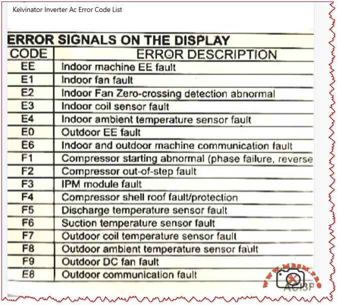
When your Kelvinator inverter split air conditioner displays an error code on the indoor unit, it is sending a critical diagnostic message. These codes—whether they appear as E‑series (E0, E1, E2, E3, E4, E6, E8) or F‑series (F1, F2, F3, F4, F5, F6, F7, F8, F9)—indicate specific faults in the refrigeration, electrical, or control systems.
Understanding what each code means empowers you to take quick action, communicate accurately with service technicians, and sometimes resolve issues without costly repairs. This guide breaks down every major error code found in Kelvinator inverter systems, the underlying causes, and professional troubleshooting steps.
Why Error Codes Matter in Inverter AC Design
Modern Kelvinator inverter air conditioners use sophisticated microprocessor controls and wireless communication between indoor and outdoor units. Unlike older fixed‑speed units, inverter models continuously adjust compressor speed to match cooling demand, saving energy but adding complexity.
When a sensor fails, a connection breaks, or the IPM module (Intelligent Power Module) overheats, the system detects the abnormality and triggers a protective shutdown with an error code display. This is not a failure of the system—it is the system protecting itself from damage.
Field technicians and homeowners who recognize these codes can:
Perform targeted checks (e.g., verify wire connections for E6 codes)
Know whether to clean filters, reset the unit, or call for service
Provide accurate fault information to repair professionals
Prevent cascading damage from overlooked issues
E‑Series Error Codes: Indoor and System‑Level Faults
The E codes generally cover sensor malfunctions, communication breakdowns, and refrigeration protection triggers. Below is the complete breakdown.
EE – EEPROM Loading Malfunction
Aspect
Details
What it means
The internal memory chip (EEPROM) that stores configuration data cannot be read or written properly.
Common causes
Power surge damage, faulty main control PCB, corrupted memory data after abnormal shutdown.
What to do
Power off for 15–30 minutes to reset memory. If it persists, contact authorized service; PCB replacement may be needed.
Field note
This code suggests electrical stress has occurred; inspect the power supply and consider surge protection.
E1 – Indoor Fan Fault
Aspect
Details
What it means
The indoor unit blower fan is not running, running intermittently, or has seized.
Common causes
Motor winding open circuit, capacitor failure, ice on coil blocking fan rotation, dust accumulation, loose wiring.
What to do
1. Check if the filter is clogged (clean if needed). 2. Listen for any grinding noise (seized bearing). 3. Visually inspect the fan blade for ice or debris. 4. If still blocked, turn off and call service.
Field note
E1 is among the most frequent codes in tropical climates due to rapid ice formation during high humidity.
E2 – Indoor Fan Zero‑Crossing Detection Abnormal
Aspect
Details
What it means
The control board cannot properly detect the fan speed signal (electrical switching transitions).
Common causes
Loose wire at the fan motor, faulty fan capacitor, wiring harness disconnection, moisture in the motor connector.
What to do
1. Power off the unit. 2. Check all wire connections at the indoor fan motor. 3. Dry any wet connectors and ensure firm seating. 4. Power on and observe. 5. If code returns, the fan motor or capacitor requires replacement.
Field note
Often occurs after extended high‑humidity operation or recent water leak in the unit.
E3 – Indoor Coil Sensor Fault
Aspect
Details
What it means
The temperature sensor on the indoor heat exchanger (evaporator coil) has failed or become disconnected.
Common causes
Sensor wire loose at connector, sensor element corroded by refrigerant or moisture, PCB connector pin bent or corroded.
What to do
1. Power off. 2. Locate the thin wire sensor in the indoor coil area (usually copper or stainless steel bulb). 3. Check the connector at the PCB. 4. Ensure the connector is fully seated and dry. 5. If clean and seated, the sensor itself has failed and must be replaced.
Field note
Refrigerant residues or corrosion inside the unit can damage sensors over time; consider coil cleaning as preventive maintenance.
E4 – Indoor Ambient Temperature Sensor Fault
Aspect
Details
What it means
The room air temperature sensor (thermistor) is open circuit, short circuit, or out of range.
Common causes
Sensor disconnected or cracked, thermistor element drifted or failed, wiring pinched behind the circuit board.
What to do
1. Power off. 2. Locate the sensor (usually a small black bulb near the air inlet). 3. Visually inspect for cracks or loose wires. 4. Gently wiggle the connector to check for poor contact. 5. If the sensor is physically damaged, replacement is required.
Field note
In dusty environments, sensor connectors can corrode; applying a small amount of dielectric grease (e.g., for automotive use) can reduce future failures.
E0 – Outdoor Unit EE Fault
Aspect
Details
What it means
The outdoor unit’s EEPROM or memory is corrupted or inaccessible.
Common causes
Power surge at outdoor unit, faulty outdoor PCB, loose connection to the outdoor unit.
What to do
1. Switch off the system for 20–30 minutes. 2. Check the outdoor unit power supply and connections. 3. Restart the system. 4. If code repeats, the outdoor control board likely has a fault. Contact authorized service.
Field note
Ensure outdoor unit is protected from direct water spray (e.g., from a hose) and covered during monsoon season to avoid electrical damage.
E6 – Indoor and Outdoor Unit Communication Fault
Aspect
Details
What it means
The wireless or wired communication link between the indoor and outdoor units has been interrupted or lost.
Common causes
Loose wire at connector, wrong wiring polarity (ground and signal reversed), interference from nearby devices, faulty communication PCB on either unit.
What to do
1. Power off completely. 2. Check the wiring harness between indoor and outdoor units at both ends. 3. Verify connections match the wiring diagram (usually in the manual). 4. If wires are correct and tight, turn on again. 5. If still E6, check for physical damage to the wiring (crushed by furniture, cut, or wet). 6. If wiring is intact, the communication module (PCB) has failed.
Field note
E6 is more common in older Kelvinator units with wireless remote communication; ensure the remote has fresh batteries and is not obstructed.
E8 – Outdoor Unit Communication Fault
Aspect
Details
What it means
Communication error originates at the outdoor unit; the display board and main control panel cannot exchange data.
Common causes
Loose harness inside the outdoor enclosure, water ingress into the control panel, damaged PCB, power supply issues to the outdoor control board.
What to do
1. Power off. 2. Inspect the outdoor unit for water damage or corrosion around connector pins. 3. Check cable connections inside the outdoor unit (may require opening the cover—use caution with live electrical components). 4. If water is present, dry the connectors and allow the unit to dry for 24–48 hours before restarting. 5. If dry and connections are tight, contact service for PCB replacement.
Field note
Heavy rain, improper drainage near the outdoor unit, or air conditioning near the ocean (salt spray) can accelerate corrosion; inspect quarterly in harsh environments.
F‑Series Error Codes: Compressor, Sensor, and Electrical Protection
The F codes indicate failures in the outdoor unit, particularly sensor, compressor, and power electronics faults. These are more critical and often require professional intervention.
F1 – Compressor Starting Abnormal (Phase Failure, Reverse Phase)
Aspect
Details
What it means
The compressor will not start due to missing phase, reversed phase sequence, or low voltage at the compressor terminals.
Common causes
Blown circuit breaker, loose wiring at the outdoor unit, reversed wiring polarity (especially in three‑phase systems), voltage too low (<200 V on 220 V system), defective IPM module.
What to do
1. Check the main circuit breaker for your air conditioner (in the electrical panel). If tripped, reset it and observe if it trips immediately (indicating a fault). 2. Measure the voltage at the outdoor unit terminals using a multimeter (should match the unit rating, e.g., 220–240 V for single‑phase). 3. If voltage is very low, there may be a cable break or loose connection. 4. If voltage is normal and the breaker holds, check wiring polarity at the outdoor connector. 5. If all electrical checks pass, the IPM module inside the outdoor unit has likely failed and requires professional replacement.
Field note
F1 is often preceded by a visible electrical event (blown breaker, lights dimming). Always verify utility supply is stable before assuming the AC is faulty.
F2 – Compressor Out‑of‑Step Fault
Aspect
Details
What it means
The compressor is not synchronizing with the control signal; it is running at the wrong speed or not running smoothly.
Common causes
Low refrigerant (gas leak), high suction pressure, mechanical jam in compressor, faulty inverter drive circuit, loose wire to compressor.
What to do
1. This code typically indicates either a refrigeration problem or a drive circuit issue. 2. Listen to the outdoor unit—does the compressor sound normal or does it stall/strain? 3. Feel (not touch directly) the outdoor copper lines for temperature difference; cold suction line and warm discharge line indicate gas is circulating. 4. If both lines are equally warm or cold, refrigerant may be depleted. 5. Do not attempt to add refrigerant without proper training. Contact a licensed technician. 6. If refrigerant lines feel normal, the inverter drive board or wiring is suspect.
Field note
F2 combined with poor cooling suggests a refrigerant leak; sealing the leak and recharging is necessary. Schedule professional service immediately to avoid compressor burnout.
F3 – IPM Module Fault
Aspect
Details
What it means
The Intelligent Power Module (IPM)—the electronic component that controls and protects the inverter compressor—has detected an internal fault or is overtemperature.
Common causes
IPM overheating due to high ambient or dirty condenser, internal IPM component failure (IGBT transistor or diode), loose thermal contact between IPM and heatsink, excessive current draw from compressor.
What to do
1. Ensure the outdoor unit condenser is not blocked by leaves, dust, or debris. Clean the condenser fins with a soft brush or compressed air. 2. Check that the outdoor fan is spinning freely when the unit runs. 3. Touch (carefully) the heatsink near the outdoor unit’s electrical panel—it should be warm but not too hot to touch for more than a few seconds (roughly <50 °C / 122 °F is acceptable during high load). 4. If the heatsink is extremely hot or the fan is not running, the IPM is likely overheating. 5. Turn off the unit and allow it to cool for 30 minutes, then restart. 6. If F3 recurs frequently during hot weather, the IPM or the cooling solution (fan, airflow) is failing. Professional service is needed.
Field note
IPM failures are a leading cause of air conditioner breakdown in Kelvinator units operating in high ambient (>40 °C / 104 °F). Ensuring adequate ventilation around the outdoor unit and cleaning the condenser monthly extends IPM life.
F4 – Compressor Shell Roof Fault / Protection
Aspect
Details
What it means
The compressor discharge temperature (measured inside the compressor shell) has exceeded safe limits.
Common causes
Low refrigerant causing the compressor to run hot, high outdoor ambient temperature, compressor motor load too high, faulty discharge temperature sensor.
What to do
1. Allow the unit to run in cooling mode with normal settings. 2. After 10 minutes of operation, touch the outdoor copper discharge line (the thin line coming from the compressor toward the condenser)—it should be hot (~60–70 °C / 140–158 °F) but not scalding. 3. Feel the suction line (larger line returning to the compressor)—it should be cool (~0–10 °C / 32–50 °F) and may have frost. 4. If suction is warm and discharge is only lukewarm, refrigerant is low. 5. If temperatures feel extreme, reduce the load (close extra rooms, reduce set temperature by just 1–2 °C) and recheck. 6. Persistent F4 with normal refrigerant suggests either a sensor fault or internal compressor damage. Contact service.
Field note
In very hot climates, F4 may occur temporarily during peak heat; if it clears after an hour of cooling and does not repeat, no action is needed.
F5 – Discharge Temperature Sensor Fault
Aspect
Details
What it means
The sensor measuring compressor discharge temperature is not responding correctly.
Common causes
Sensor wire disconnected or pinched, sensor element burnt out, PCB connector corroded or loose.
What to do
1. Power off the unit. 2. Locate the discharge temperature sensor on the outdoor unit (a small bulb or wire-wound sensor). 3. Visually inspect for loose or damaged wiring. 4. Check the connector at the outdoor PCB is fully seated. 5. If connections are sound, the sensor element itself has failed. Replacement is required.
Field note
Discharge sensors are often damaged when the compressor runs with depleted refrigerant; always confirm refrigerant level is adequate before replacing the sensor.
F6 – Suction Temperature Sensor Fault
Aspect
Details
What it means
The sensor measuring refrigerant suction (inlet) temperature is faulty.
Common causes
Similar to F5: disconnected wire, burnt-out sensor element, corroded PCB connector.
What to do
1. Power off. 2. Locate the suction temperature sensor (usually clipped to the large copper suction line entering the compressor). 3. Check for loose or torn wiring. 4. Verify the connector is dry and fully seated at the PCB. 5. If intact, the sensor requires replacement.
Field note
Suction sensors are robust but can corrode if refrigerant moisture is present; proper evacuation and drying during any compressor service prevents this fault.
F7 – Outdoor Coil Temperature Sensor Fault
Aspect
Details
What it means
The condenser (outdoor heat exchanger) temperature sensor is open circuit, short, or out of range.
Common causes
Wire disconnected or pinched under the condenser, sensor element failed, moisture in the connector causing corrosion.
What to do
1. Power off. 2. Inspect the outdoor condenser area for loose sensor wires or connections. 3. Check the routing of the sensor lead—ensure it is not pinched between the condenser fins or trapped under a mounting bracket. 4. Dry any wet connectors. 5. Retest. 6. If the wire is intact and dry, the sensor element has failed and must be replaced.
Field note
High-pressure water spray during cleaning can push water into sensor connectors; use a soft brush instead of direct spray.
F8 – Outdoor Ambient Temperature Sensor Fault
Aspect
Details
What it means
The outdoor air temperature sensor is disconnected, damaged, or is reporting an out-of-range value.
Common causes
Loose wire at the outdoor wall-mounted sensor, sensor bulb cracked, PCB connector pin bent or corroded, sensor element drifted due to age.
What to do
1. Power off. 2. Locate the outdoor ambient sensor (a small round or bulbous device mounted on the outdoor unit casing). 3. Check for cracks or loose wiring. 4. Ensure the connector is clean, dry, and fully seated. 5. If all connections are sound, the sensor element has failed and needs replacement.
Field note
Outdoor sensors are exposed to sunlight and temperature swings; replacing every 5–7 years is a reasonable preventive measure.
F9 – Outdoor DC Fan Fault
Aspect
Details
What it means
The outdoor condenser fan is not running, running at wrong speed, or has stalled.
Common causes
Fan motor capacitor failed, motor bearing seized, blade obstruction (leaves, debris, ice), loose wiring at the fan connector, voltage drop in supply.
What to do
1. Power off and unplug. 2. Spin the fan blade by hand—it should rotate freely and smoothly without grinding. 3. If it binds, the bearing is seized; the motor requires replacement. 4. If it spins freely, check for blocked airflow (dust, leaves, insects). Clean the condenser and surrounding area. 5. Inspect the fan motor capacitor (if accessible) for bulging or leakage; a capacitor with dried-out ends likely has failed. 6. Power back on and listen. If the fan still does not run, check the connector at the PCB. 7. If the connector is tight and dry but the fan does not run, the motor has failed.
Field note
The fan capacitor is a common wear item in tropical climates; proactive replacement every 2–3 years prevents sudden failure.
E8 (Continued) – Outdoor Communication Fault
Covered above in E-series; also applies to outdoor control issues.
Comparison: Kelvinator Error Codes vs. Other Inverter AC Brands
To help technicians working across multiple brands, the table below compares how similar faults are coded.
Fault Description
Kelvinator
Midea / AUX
Carrier
Haier
Orient
Outdoor unit fan fault
F9
F0
F0
F0
F0
IPM module overtemp/fault
F3, F7
F7 (IPM temp)
F5 (IPM)
F1 (IPM)
F5 (IPM)
Compressor start abnormal
F1
F6 (phase), F1 (IPM)
EC, F1
F1
F1
Refrigerant leak (low pressure)
E3
E3, E5
E3
E3
E3
Communication error
E6, E8
E6
E1
E6
E6
Room temp sensor fault
E4
E2
E2
E2
E2
Coil temp sensor fault
E3
E1
E4
E1
E1
Discharge temp sensor fault
F5
F2
F2
F2
F2
Fan motor fault
E1
E0
E0
E0
E0
Key insight: Although brand coding differs, the underlying components and fault mechanisms are nearly identical. A technician familiar with one brand can quickly learn another by cross-referencing sensor and module names.
Practical Troubleshooting Flowchart for Kelvinator Error Codes
When an error code appears, use this systematic approach:
Step 1: Identify and Record the Code Write down the exact code (e.g., F3, E6). Check the display in different light and from different angles to confirm the character.
Step 2: Safety First Before troubleshooting, ensure power is safely isolated. If you are unsure, do not open electrical enclosures.
Step 3: Quick Reset Turn off the unit at the wall switch or circuit breaker. Wait 15–30 minutes, then restart. Many codes clear if they were temporary electrical glitches.
Step 4: Visual Inspection
E1, E2, F9: Check filter and fan visually for blockage or damage.
E3, E4, F5, F6, F7, F8: Inspect all visible sensor wires for disconnection, pinching, or damage.
E6, E8: Check wiring between indoor and outdoor units.
F1, F3: Check outdoor unit for debris, ensure fan moves freely, verify power supply.
Step 5: Component Testing (if equipped with a multimeter)
For sensor faults, measure resistance of the sensor element. A typical thermistor should read a few thousand ohms; an open circuit (∞) or zero ohms indicates failure.
For wiring faults, check continuity along the suspected wire path.
For power faults, verify voltage at key points matches the unit specification.
Step 6: Document and Report If the error recurs or you cannot identify the cause, note:
Time of day and outdoor ambient temperature.
How many minutes the unit ran before the error appeared.
Any recent weather events, power outages, or changes to the setup.
Any sounds or odors noticed.
Provide this information to the service technician to speed diagnosis.
Professional Advice: Maintenance to Prevent Errors
Many Kelvinator error codes can be prevented through regular maintenance:
Filter Cleaning (Monthly) A clogged filter reduces airflow, lowers cooling efficiency, and triggers E1 (fan fault). Clean the filter or replace it every month during cooling season.
Condenser Inspection (Quarterly) Outdoor dust, leaves, and debris block airflow, causing F3 (IPM overtemp) and F9 (fan fault). Gently clean the outdoor unit with a soft brush or compressed air.
Wiring Inspection (Annually) Visual inspection of all connectors and wiring harnesses (between indoor and outdoor units) can catch loose connections before they trigger E6 or E8 codes.
Sensor Bulb Checks (Annually) Visually inspect temperature sensor bulbs for physical damage, corrosion, or frost buildup. Replace any that appear damaged.
Refrigerant Level (Every 2–3 years) Have a licensed technician verify refrigerant charge. Low gas causes F1, F2, and F4 codes and reduces cooling.
IPM and Capacitor Condition (Every 3–5 years) In high-temperature climates or after many operating hours, have the outdoor electrical components inspected. Proactive capacitor replacement (a wear item) prevents sudden shutdowns.
Error Code Scenarios: Real-World Examples
Scenario 1: E1 Code During Night Operation in High Humidity
What happened: Unit ran fine during the day. At night, E1 appeared and the fan stopped.
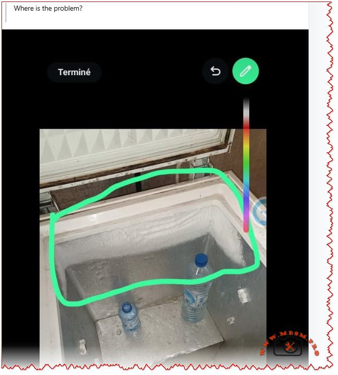
Diagnosis: High nighttime humidity combined with cold evaporator coil caused ice to form on the indoor coil fins, blocking the fan.
Solution: Run the unit in dry mode or reduce the set temperature by 2 °C. Allow ice to melt for 30 minutes. If E1 repeats nightly, ensure the drain pan is not clogged (preventing condensate drainage).
Prevention: Clean the air filter monthly; clogging accelerates ice formation.
Scenario 2: F3 Error on the First Hot Day of Summer
What happened: Unit worked fine during spring. As outdoor temperature jumped to 38 °C (100 °F), F3 (IPM overtemp) appeared after 20 minutes of cooling.
Diagnosis: IPM module is overheating. The outdoor unit’s condenser fins were heavily dust-clogged from months of standby.
Solution: Power off, clean the outdoor condenser thoroughly, ensure outdoor fan runs without obstruction. Restart in the early morning (cooler ambient). F3 should not recur.
Prevention: Clean the outdoor condenser before each cooling season.
Scenario 3: E6 Code After Electrician Service
What happened: Technician serviced the circuit breaker panel. Shortly after, E6 (communication fault) appeared.
Diagnosis: During electrical panel work, a wire was shifted or the communication cable between indoor and outdoor units was bumped loose.
Solution: Inspect the wiring harness connections at both the indoor and outdoor unit terminals. One connector was half-seated; pushing it home resolved E6.
Prevention: Always verify that service technicians reconnect all wiring exactly as found.
When to Call a Professional
Contact an authorized Kelvinator service technician immediately if:
F1, F2, F3, F4 appear: These indicate compressor or drive system issues requiring specialized testing equipment.
F5, F6, F7, F8: Sensor faults usually require replacement; test equipment is needed to confirm.
E0, EE, E8 persist after a 30-minute reset: Indicates potential PCB failure.
E6 remains after checking all visible wiring and connectors: Suggests a deeper communication problem.
Any error code accompanied by sparks, burning smell, or water leaks: Turn off immediately and call emergency service.
Benefits of Understanding Error Codes
Faster Resolution: You can provide exact information to technicians, reducing diagnostic time.
Preventive Action: Recognizing early warning patterns helps avoid catastrophic failures.
Cost Savings: Simple fixes (cleaning, resetting) sometimes clear codes without service calls.
System Longevity: Regular maintenance triggered by code patterns extends the life of your inverter AC by years.
Comprehensive Kelvinator inverter air conditioner error code guide. Understand E‑series (E1, E2, E3, E4, E6, E8) and F‑series (F1–F9) faults, causes, and professional troubleshooting steps for compressor, sensor, and communication failures.
Kelvinator error codes, inverter AC troubleshooting, E1 E2 E3 E4 F1 F2 F3 fault code, air conditioner error diagnosis, compressor protection, IPM module fault, communication error E6, sensor failure, HVAC troubleshooting, Mbsmgroup, Mbsm.pro, mbsmpro.com, mbsm, AC maintenance, inverter compressor
Excerpt (first 55 words)
When your Kelvinator inverter split air conditioner displays an error code (E1, E2, E3, F1, F2, F3, etc.), it is signaling a specific system fault. This comprehensive guide explains every major error code—from sensor failures and communication breakdowns to compressor and power module protection triggers—and provides professional troubleshooting steps.
Kelvinator Inverter AC, Error mbsmpro
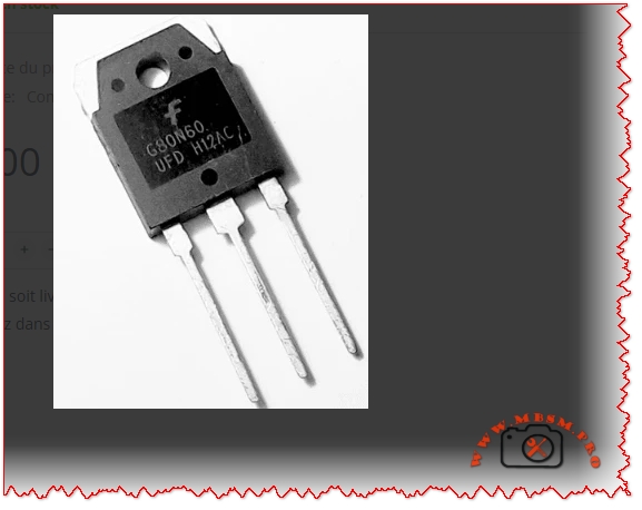
Transistor IGBT, G80N60UFD, 600 V, 80 A
Category: Electronic
written by www.mbsmpro.com | January 12, 2026
Mbsmpro.com, Transistor IGBT, G80N60UFD, 600 V, 80 A, Ultrafast, TO‑3P, Motor Drive, Inverter, Induction Heating, Welding, UPS, PFC
Overview of the G80N60UFD Ultrafast IGBT 600 V, 80 A
The G80N60UFD is an ultrafast insulated‑gate bipolar transistor (IGBT) designed for high‑efficiency power conversion around 600 V DC buses and up to 80 A collector current. It uses Fairchild / ON Semiconductor UFD technology with a co‑pack fast recovery diode, optimized for high‑frequency switching, low conduction loss and robust avalanche capability.
For a field technician or design engineer, this component is a solid choice in demanding power stages where classic MOSFETs start to lose efficiency at high voltage and bipolar transistors switch too slowly.
Key Electrical Characteristics of G80N60UFD
The following table summarizes the main parameters typically found in the official datasheet (25 °C, unless noted). Always confirm against the latest datasheet of your specific manufacturer / batch.
Parameter
Symbol
Typical / Max Value
Notes
Collector‑Emitter Voltage
V<sub>CES</sub>
600 V
Repetitive, IGBT off
Continuous Collector Current @ 25 °C
I<sub>C</sub>
80 A
With proper heatsink
Pulsed Collector Current
I<sub>CP</sub>
>160 A (typ.)
Limited by T<sub>j</sub>
Gate‑Emitter Voltage (max)
V<sub>GE</sub>
±20 V
Never exceed in drive design
Collector‑Emitter Saturation Voltage
V<sub>CE(sat)</sub>
~2.1–2.6 V @ 40–80 A
Strong conduction capability
Junction Temperature Range
T<sub>j</sub>
−55 to +150 °C
Industrial class
Typical Gate Charge
Q<sub>g</sub>
~160–200 nC
Important for driver sizing
Total Power Dissipation @ 25 °C Case
P<sub>D</sub>
≈195 W
With ideal heatsink
Package Type
–
TO‑3P / TO‑247‑3
Through‑hole, isolated tab versions exist
Internal Structure and How the G80N60UFD Works
The IGBT combines:
A MOSFET gate structure for very high input impedance and easy gate drive.
A bipolar output section for low on‑state voltage at high current.
In the G80N60UFD, the ultrafast diode is co‑packaged with the IGBT die. This diode clamps inductive energy during free‑wheel phases and is optimized for:
Low reverse recovery time (t<sub>rr</sub> ≈ tens of ns)
Low reverse recovery charge (Q<sub>rr</sub>), reducing switching losses and EMI.
This makes the device suitable for switching frequencies typically between 15 kHz and 40 kHz, depending on cooling and losses.
Comparison: G80N60UFD vs. FGH80N60FD vs. Classic 600 V MOSFET
To position the G80N60UFD in a design, it is useful to compare it with a close relative (FGH80N60FD, another 600 V / 80 A field‑stop IGBT) and a generic 600 V MOSFET around 60–70 mΩ R<sub>DS(on)</sub>.
Feature / Device
G80N60UFD (UFD series)
FGH80N60FD (Field‑stop)
Typical 600 V MOSFET 60–70 mΩ
Device Type
Ultrafast IGBT + Diode
Field‑stop IGBT
Power MOSFET
V<sub>CES</sub> / V<sub>DSS</sub>
600 V
600 V
600–650 V
I<sub>C</sub> / I<sub>D</sub> (cont.)
80 A
80 A
40–50 A (depending on package)
Conduction Loss @ 40–50 A
Low (V<sub>CE(sat)</sub> ≈ 2 V)
Very low (≈1.8 V)
Higher (I × R<sub>DS(on)</sub>)
Switching Speed
Very fast (UFD)
Very fast (field‑stop)
Fast but high capacitance
Best Frequency Range
10–30 kHz
10–30 kHz
Up to 60–80 kHz (lower current)
Gate Drive
±15 V typical
±15 V typical
10–12 V typical
Ideal Applications
Motor drives, UPS, welding, induction heating
PFC, ESS, telecom, induction heating
SMPS, PFC, lower power drives
Engineering conclusion: At 80 A level and 600 V bus, the G80N60UFD offers better efficiency and robustness than many single MOSFETs, especially in applications where conduction loss dominates. The FGH80N60FD is a newer field‑stop variant with slightly lower V<sub>CE(sat)</sub>, but in many real installations the difference is small compared with cooling and PCB layout quality.
Typical Applications for G80N60UFD 600 V, 80 A
Because of its fast switching and strong current capability, this device is widely used in:
AC and DC motor drives (industrial motors, pumps, fans, compressors).
Inverter stages of solar, UPS, and battery storage systems with 300–400 V DC buses.
Induction heating and welding machines where rapid current commutation is necessary.
High‑power SMPS and PFC stages up to several kilowatts.
Servo controls and robotics requiring efficient torque control.
Practical Gate Drive and Protection Considerations
Recommended Gate Drive Strategy
Parameter
Typical Design Value
Comment
Gate drive voltage
+15 V ON, 0 V or −5 V OFF
Negative off‑bias improves immunity
Gate resistor R<sub>G</sub>
5–15 Ω
Balance of dV/dt, EMI, losses
Gate driver type
Isolated driver with Miller clamp
For safe high‑side / low‑side control
Desaturation / over‑current sense
Recommended
Rapid fault turn‑off
Gate‑emitter Zener clamps
18–20 V
Protect gate from surges
Using too small a gate resistor may reduce switching losses but increases dV/dt and EMI, and can push the device into unsafe operating areas. Field experience shows that a compromise around 8–12 Ω works well for most industrial inverters.
Thermal Design and Heatsink Selection
IGBTs at this power level must be treated as thermal devices as much as electrical ones.
Approximate thermal path:
Junction‑to‑case R<sub>θJC</sub> ≈ 0.6–0.7 °C/W
Case‑to‑heatsink (with proper thermal grease and insulation) ≈ 0.2–0.3 °C/W
Heatsink‑to‑ambient R<sub>θSA</sub> chosen for required temperature rise
Example design thought:
If the G80N60UFD is expected to dissipate 60 W average, and the maximum ambient is 40 °C, you want junction temperature below 125 °C for reliability:
Allowed ΔT<sub>JA</sub> ≈ 125 – 40 = 85 °C
Required total R<sub>θJA</sub> = 85 / 60 ≈ 1.4 °C/W
Subtracting R<sub>θJC</sub> + R<sub>θCS</sub> (~1.0 °C/W) gives ≈0.4 °C/W for the heatsink. This means a large finned heatsink, often with forced air for continuous high‑load operation.
Example Application Schematic: Single‑Phase Inverter Leg Using G80N60UFD
Below is a simplified textual schema style you can graphically reproduce in your WordPress article:
DC Bus: 325–400 V from rectified mains or battery bank
Upper Switch (Q1): G80N60UFD
Lower Switch (Q2): G80N60UFD
Freewheel Diodes: co‑pack diodes in each IGBT, no extra ultrafast diode normally needed
Gate Driver: high‑side/low‑side driver IC with isolated supply (for example 15 V).
Snubber Network: RC or RCD across each IGBT (e.g., 100 nF / 1–2 kΩ / 600 V film capacitor)
Current Sense: shunt resistor or Hall sensor on the DC bus or emitter leg.
Control: Microcontroller or DSP generating complementary PWM with dead‑time (200–500 ns).
This half‑bridge cell can be duplicated to create:
Three‑phase motor drives.
Full‑bridge inverters for UPS or photovoltaic systems.
Push‑pull or full‑bridge induction heating converters.
Comparison of G80N60UFD With Lower‑Power IGBT Devices
For designers stepping up from smaller IGBTs, the following table shows why the G80N60UFD is in a different league.
Parameter
30 A / 600 V IGBT (generic)
50 A / 600 V IGBT (generic)
G80N60UFD 80 A / 600 V
Continuous current
30 A
50 A
80 A
Peak current capability
~60 A
~100 A
≥160 A
Recommended max power stage
<2 kW
2–3 kW
3–6 kW or more
V<sub>CE(sat)</sub> at nominal current
≈2.2–2.5 V
≈2.2–2.5 V
Comparable or slightly lower
Package
TO‑220 or TO‑247
TO‑247
TO‑3P / TO‑247‑3 large tab
Cooling requirement
Medium
Medium‑high
High, usually forced air
When your application moves beyond about 3 kW at 230 V AC, investing in G80N60UFD‑class devices plus serious thermal management is normally more economical than paralleling several smaller IGBTs.
Installation Tips, Field Notes and Reliability Advice
From a practical maintenance and design point of view, these points can make the difference between a reliable inverter and a burner of semiconductors:
Respect dV/dt limits Fast devices like the G80N60UFD generate steep voltage transitions. Keep loop area small (short bus bars, wide copper), and use proper snubber networks to limit overshoot.
Gate drive layout Route gate and emitter (return) traces as a twisted pair or very close tracks. A shared emitter path with power current causes false turn‑on through Miller capacitance.
Heatsink and mounting
Use a flat, clean surface, thin thermal compound, and correct screw torque.
Consider insulating pads if the collector tab must be isolated from chassis.
After mounting, always check for shorts between tab and heatsink with a megohmmeter.
Current sharing if paralleled Parallel use is possible but requires careful design: equal gate resistors, matched wiring lengths, shared heatsink, and sometimes small emitter resistors to encourage current balancing.
EMI compliance Use common‑mode chokes, proper shielding, and LC filters on the mains or DC input. A badly filtered high‑power IGBT bridge can exceed EMC limits easily.
Protection coordination Combine fast electronic protection (desaturation, overcurrent, over‑temperature) with slower fuses or circuit breakers. A fuse alone is not fast enough to save an IGBT at 80 A.
Advantages and Practical Benefits of Using G80N60UFD
Higher efficiency in medium‑frequency power converters compared with slower IGBTs and many high‑voltage MOSFETs.
Integrated ultrafast diode reduces component count and PCB area.
Robust structure tolerates industrial environments and transient conditions when properly designed.
Good compromise between conduction loss and switching loss, ideal for inverters running around 16–20 kHz.
For HVAC compressors, industrial pumps and fans, welding machines, induction cookers or heaters, upgrading an older design to G80N60UFD‑class devices often results in:
Lower operating temperature of the power stage.
Better efficiency (sometimes several percentage points).
Increased reliability and longer service intervals.
Design Recommendations and Professional Advice
Start from the datasheet safe operating area (SOA). Do not design only from RMS current. Check short‑circuit withstand time, repetitive peak current, and switching SOA.
Simulate first, verify later. Use SPICE or vendor models for G80N60UFD (or SGH80N60UFD / FGH80N60FD equivalents) to simulate switching losses and junction temperature over a complete load cycle.
Always measure in the real system. A good differential probe and current clamp are essential to verify waveforms, dV/dt, and peak currents. Adjust gate resistors and snubbers based on real measurements, not only theoretical calculations.
Plan for serviceability. Place IGBTs on easily accessible heatsink areas, label them clearly, and keep some mechanical margin so modules can be replaced without damaging PCB traces.
Document thermal and electrical limits in the maintenance manual. Technicians must know maximum current, duty cycle, and temperature targets. This reduces the risk of field modifications that push devices out of their safe area.
Focus Keyphrase (≤191 characters)
G80N60UFD IGBT 600 V 80 A ultrafast transistor, TO‑3P power switch for motor drive, inverter, induction heating, welding, UPS, PFC and high‑efficiency industrial converters
SEO Title
G80N60UFD IGBT 600 V, 80 A – Ultrafast Power Transistor for Motor Drives, Inverters, Induction Heating and Welding | Mbsmpro.com
Meta Description
A detailed engineering guide to the G80N60UFD 600 V, 80 A ultrafast IGBT. Characteristics, comparison with other 600 V devices, thermal design, gate drive, inverter schematics, and professional tips for reliable industrial power stages.
The G80N60UFD is an ultrafast 600 V, 80 A insulated‑gate bipolar transistor in a robust TO‑3P package, designed for high‑efficiency industrial inverters. Combining MOSFET‑like gate control with low saturation voltage and a co‑pack fast recovery diode, it is ideal for motor drives, induction heating, welding machines, UPS and PFC stages.
MCB miniature circuit breaker thermal magnetic protection mechanism
Category: Global Electric
written by www.mbsmpro.com | January 12, 2026
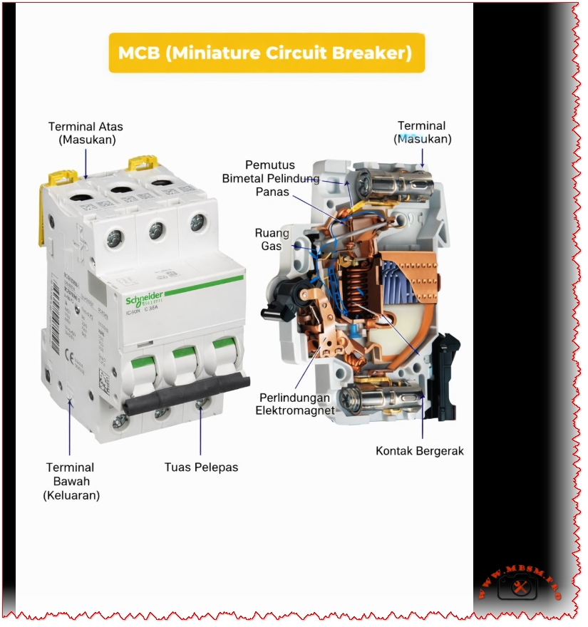
MCB (Miniature Circuit Breaker): Complete Guide to Thermal Magnetic Protection Technology
FOCUS KEYPHRASE (Max 191 characters)
MCB miniature circuit breaker thermal magnetic protection mechanism bimetallic overload short circuit electrical safety
META DESCRIPTION (155-160 characters)
Discover how MCB miniature circuit breakers work with thermal-magnetic protection. Complete technical guide to overload and short-circuit safety mechanisms.
An MCB (Miniature Circuit Breaker) is an automatic electrical switch that protects circuits from overloads and short circuits. Using dual thermal-magnetic mechanisms, MCBs detect abnormal currents and instantly disconnect power to prevent equipment damage and fire hazards. Compact, reliable, and essential for modern electrical safety.
MCB (Miniature Circuit Breaker): The Complete Technical Guide to Thermal-Magnetic Protection
Introduction: What is an MCB?
An MCB (Miniature Circuit Breaker) represents one of the most critical innovations in electrical safety systems. This automatic protective device safeguards residential, commercial, and industrial electrical installations by instantly interrupting power flow when dangerous conditions occur. Unlike traditional fuses that require replacement, modern MCBs offer reusable, reliable protection through intelligent dual-mechanism technology.
The primary function of an MCB is straightforward yet vital: detect abnormal electrical conditions and automatically isolate the circuit before damage occurs. Whether protecting a household appliance or industrial machinery, MCBs serve as the first line of defense against electrical hazards.
How MCB Works: Understanding the Dual Protection System
The Thermal Protection Mechanism
The thermal component of an MCB employs a sophisticated bimetallic strip—a thin metal band created by bonding two different metals together. These metals possess different thermal expansion coefficients, meaning they expand at different rates when heated.
The thermal process operates as follows:
Normal Operation – Under rated current conditions, heat generation is minimal. The bimetallic strip remains relatively straight.
Overload Detection – When current exceeds the MCB’s rated capacity, excessive heat causes unequal expansion between the two bonded metals.
Strip Deflection – The differential expansion forces the bimetallic strip to bend or curve progressively.
Mechanical Latch Release – Once the strip bends sufficiently, it physically releases a mechanical latch mechanism.
Contact Separation – The released latch triggers the operating mechanism to open the electrical contacts, stopping current flow.
Key Characteristic: Thermal protection provides delayed response, making it ideal for sustained overload situations lasting seconds to minutes.
The Magnetic Protection Mechanism
While thermal protection handles gradual overloads, magnetic protection addresses immediate threats from short circuits.
Inside each MCB exists a solenoid coil (electromagnet) that surrounds the electrical contacts. When current flows normally, the magnetic field strength remains insufficient to trigger action.
The magnetic response sequence:
Short Circuit Occurrence – A fault suddenly causes current to spike to dangerous levels (often 10-100 times the rated current).
Magnetic Field Generation – The solenoid coil creates an intense electromagnetic field proportional to current magnitude.
Armature Attraction – This powerful magnetic field attracts an armature (movable iron piece) at lightning speed.
Instant Contact Opening – The armature movement triggers an override mechanism that forces electrical contacts open within milliseconds.
Arc Suppression – Specialized components called arc contacts and gas-filled chambers extinguish any electrical arc that forms during contact separation.
Key Characteristic: Magnetic protection provides instantaneous response (typically 10-50 milliseconds), protecting against catastrophic short-circuit damage.
MCBs come in standardized current ratings, each suited to specific applications:
MCB Rating (Amperes)
Typical Application
Common Use
0.5A – 2A
High-sensitivity circuits
Lighting, low-power sensors
3A – 6A
General lighting circuits
Residential household lighting
10A – 13A
Standard domestic circuits
Appliances, outlets, general power
16A – 20A
Heavy-duty domestic use
Kitchen appliances, water heaters
25A – 32A
Industrial and commercial
Industrial machinery, heavy loads
40A – 63A
Large installations
Industrial production lines
80A – 125A
Main distribution systems
Building main switchboards
Expert Recommendation: Select MCB ratings based on wire gauge and actual load requirements, not convenience. Undersized MCBs trip frequently; oversized units provide inadequate protection.
Voltage Specifications
MCBs operate within defined voltage ranges:
Single-Phase MCBs: 230V (standard residential in most countries)
Three-Phase MCBs: 400V (industrial applications)
Dual-Voltage Models: Can operate at both 230V and 400V
Breaking Capacity (Interrupting Rating)
This critical specification indicates the maximum short-circuit current an MCB can safely interrupt without sustaining damage. Measured in kiloamperes (kA), breaking capacity values typically range from 3 kA to 25 kA:
Breaking Capacity
Application Suitability
Typical Environment
3 kA – 6 kA
Lightweight residential use
Modern suburban homes, low-fault areas
10 kA
Standard domestic/commercial
Typical apartment buildings, offices
15 kA – 25 kA
Industrial and high-fault areas
Factories, power-dense facilities
Critical Safety Note:Never install an MCB with insufficient breaking capacity for your electrical system’s fault level. Exceeding breaking capacity causes dangerous failure.
MCB Curve Types: Matching Protection to Application
MCBs employ different tripping characteristics, designated by letters B, C, and D. Each curve represents how quickly the MCB responds to different multiples of rated current:
Type B Curve MCBs
Magnetic Trip Threshold: 3–5 times rated current
Optimal For: Purely resistive loads with minimal inrush current
Applications: Incandescent lighting, resistive heaters, general residential wiring
Response Time: Fast, but slightly delayed for transient spikes
Type C Curve MCBs(Most Common in Residential/Commercial)
Magnetic Trip Threshold: 5–10 times rated current
Optimal For: Mixed loads with moderate inrush currents
Applications: Standard household circuits, office equipment, small motors, the most versatile choice
Response Time: Balanced between nuisance tripping and protection
Industry Standard: Nearly universal choice for general-purpose installations
Type D Curve MCBs
Magnetic Trip Threshold: 10–20 times rated current
Optimal For: Loads with high inrush currents
Applications: Large motors, transformers, industrial machinery, welding equipment, compressors
Response Time: More forgiving of startup transients, essential for heavy industrial loads
Comparison Table: MCB Curve Selection
Characteristic
Type B
Type C
Type D
Magnetic Sensitivity
Very High (3–5×)
Medium (5–10×)
Low (10–20×)
Residential Use
Specific applications
General standard
Rare
Commercial Use
Limited
Standard
Industrial
Motor Protection
Poor
Fair
Good
Inrush Tolerance
Minimal
Moderate
High
Cost
Low
Low
Moderate
Reliability
Good
Excellent
Good
Thermal vs. Magnetic Protection: Complementary Systems
The brilliance of MCB design lies in combining these two protection mechanisms, each handling distinct fault scenarios:
When Does Thermal Protection Activate?
Thermal protection engages during gradual overload conditions:
Current exceeds rated value but remains below magnetic threshold
Heat gradually accumulates in the bimetallic strip
Activation Time: 5 seconds to several minutes depending on overload magnitude
Magnetic protection engages during sudden, catastrophic faults:
Current spikes instantly to dangerous levels (short circuits, direct faults)
Electromagnetic field builds instantly
Activation Time: 10–50 milliseconds (near-instantaneous to human perception)
Examples: Touching live wires, equipment short circuits, electrical arcing, damaged insulation allowing conductors to contact each other
Synergistic Protection Table
Scenario
Thermal Response
Magnetic Response
Outcome
Overloaded circuit (sustained)
✓ TRIGGERS
– Remains inactive
MCB trips safely
Short circuit (sudden)
– Inactive
✓ TRIGGERS
Instant protection
High inrush current (motor start)
– Tolerates
– Tolerates (if Type C/D)
No false trips
Combination overload + fault
✓ TRIGGERS
✓ TRIGGERS
Redundant protection
MCB vs. MCCB: Understanding the Key Differences
Confusion often arises between MCBs and MCCBs (Molded Case Circuit Breakers). While both protect circuits, they serve fundamentally different applications:
When bonded together and heated, differential expansion forces the assembly to curve. This design allows precise calibration: engineers adjust strip thickness, length, and material composition to achieve exact trip temperatures for specific current ratings.
Solenoid Coil Specifications
The electromagnet comprises:
Copper Wire Winding – Typically 500–1,000 turns depending on design
Soft Iron Core – Concentrates magnetic field for maximum strength
Precise Calibration – Coil parameters engineered to trigger at exact current multiples
Electrical Contacts
MCBs employ specialized contacts:
Main Contacts – Silver-plated for electrical conductivity and corrosion resistance
Arc Contacts – Harder metals (tungsten or molybdenum) that resist electrical erosion
Arc Suppression Chamber – Quartz sand or gas chamber that cools and extinguishes arcs during contact separation
Contact Material Longevity – Typically 10,000+ mechanical operations before replacement consideration
Installation Best Practices: Expert Recommendations
Critical Safety Considerations
1. Proper Circuit Protection Coordination
MCBs must be strategically sized:
Consideration
Guideline
Rationale
Wire Gauge Matching
MCB rating ≤ wire ampacity
Prevents wire overheating before MCB trips
Selective Coordination
Downstream MCBs trip first
Isolates faults to affected circuit only
Load Calculation
Sum actual amperes + 25% safety margin
Accounts for seasonal variations, equipment aging
2. Ambient Temperature Compensation
MCB performance varies with temperature:
High Temperatures (>40°C): Thermal element becomes more sensitive; may trip prematurely on normal loads
Low Temperatures (<20°C): Reduced sensitivity may delay thermal tripping
Solution: Select MCBs with ambient temperature ratings appropriate for installation environment
3. Curve Selection Validation
Test inrush currents before installation:
Measure startup currents of motors and transformers
Compare against MCB curve trip thresholds
Ensure adequate margin to prevent nuisance tripping
Installation Sequence
Power Isolation – Ensure main supply disconnection and lockout/tagout procedures
DIN-Rail Preparation – Install on properly grounded DIN rail at 35mm width nominal
Clearance Verification – Ensure minimum 25mm clearance between pole terminals
Labeling – Permanently mark circuit identification on MCB or adjacent labeling
Testing – Verify manual trip mechanism and test circuit integrity before energization
Common MCB Failures: Diagnosis and Prevention
Premature or Nuisance Tripping
Symptom: MCB repeatedly trips without apparent overload
Possible Causes:
Undersized MCB for actual circuit load
Inrush current from motor/transformer exceeding Type C tolerance
Moisture infiltration or environmental stress
Internal mechanical wear after years of service
Solutions:
Calculate actual circuit load accurately and upsize appropriately
Switch to Type D MCB if high-inrush loads present
Ensure panel installation in dry, temperature-controlled environment
Replace MCB if mechanical wear suspected
Failure to Trip (Safety Hazard)
Symptom: Dangerous overload or short circuit occurs without MCB response
Possible Causes:
Undersized breaking capacity for fault current level
Contact welding from arc damage
Mechanical jamming or corrosion
Electromagnetic coil failure
Critical Action:Immediately disconnect circuit and replace MCB. This represents serious safety risk.
Thermal Drift or Inconsistent Performance
Symptom: MCB trips at different current levels depending on temperature or recent history
Possible Causes:
Bimetallic strip metal fatigue from repeated heating cycles
Environmental temperature extremes affecting thermal sensitivity
Interaction between thermal and magnetic mechanisms during simultaneous stress
Resolution: Replacement with fresh MCB or upgrade to premium models with enhanced thermal stability.
Advantages of Modern MCB Technology
Superior Safety Profile
✓ Automatic Response – Eliminates human error inherent with manual switches ✓ Dual Protection – Simultaneously protects against overload and short-circuit hazards ✓ Arc Containment – Suppresses dangerous electrical arcing within device ✓ Fire Prevention – Eliminates arc-induced fires common with older protection methods
Operational Benefits
✓ Reusable – Simple manual reset vs. fuse replacement ✓ Compact Design – Space-efficient compared to older switches ✓ Fast Response – Magnetic protection responds in milliseconds to short circuits ✓ Visual Indication – Handle position clearly shows ON/OFF/TRIPPED status
Economic Advantages
✓ Long Lifespan – 10,000+ mechanical operations typical ✓ Low Maintenance – No periodic adjustment or recalibration required ✓ Minimal Replacement Cost – €3–15 vs. industrial circuit breaker costs ✓ Reduced Downtime – Instant reset vs. fuse procurement and installation delay
Compatibility and Flexibility
✓ Standardized Mounting – Industry-standard DIN-rail compatibility ✓ Modular Design – Mix single, double, triple-pole configurations ✓ Curve Selection – Type B, C, D options for different load characteristics ✓ Retrofit Capability – Replace older protection systems without major reconstruction
Specialized MCB Variants: Advanced Protection
RCBO (Residual Current Breaker with Overcurrent Protection)
An RCBO combines MCB functionality with residual current detection:
Additional Feature: Detects current imbalance between live and neutral conductors
Protection Against: Electric shock, particularly in wet environments (bathrooms, kitchens, outdoors)
Sensitivity: Typically 30mA (milliampere) trip threshold
Standards: IEC 61008, European standard for shock protection
RCBO vs. Standard MCB:
Aspect
Standard MCB
RCBO
Overload Protection
✓ Yes
✓ Yes
Short Circuit Protection
✓ Yes
✓ Yes
Electric Shock Protection
✗ No
✓ Yes
Wet Location Suitability
Poor
Excellent
Cost
Low
Higher
Complexity
Simple
Advanced
Earth Leakage Circuit Breaker (ELCB)
Older technology now largely replaced by RCBO:
Detects current leakage to earth (ground)
Less precise than modern residual current detection
Still found in some legacy installations
Recommendation: Upgrade to RCBO for superior protection
MCB Selection Guide: Practical Decision Tree
Step 1: Determine Application Type
textIs this installation...?
├─ Residential (home) → Go to Step 2A
├─ Commercial (office/retail) → Go to Step 2B
└─ Industrial (factory/heavy equipment) → Consider MCCB instead
Step 2A: Residential Circuit Calculation
For each circuit:
Identify all connected devices (lights, outlets, appliances)
Look up power ratings (typically labeled in watts or amps)
Calculate total: Sum all amps for simultaneous operation
Add 25% Safety Margin: Multiply by 1.25
Select MCB: Choose standard rating ≥ calculated value
Compliance Verification: Check for certification marks on MCB body (CE, UL, RoHS symbols indicating standards compliance).
Maintenance and Lifecycle Management
Routine Inspection Protocol
Quarterly:
Visual inspection for corrosion, discoloration, or damage
Verify handle moves freely in ON/OFF positions
Check panel labeling remains legible
Annually:
Test trip mechanism by manually switching to OFF position
Restore to ON; confirm circuit continuity
Document any sluggish operation requiring investigation
Every 5 Years:
Professional inspection by qualified electrician
Electrical testing to verify trip thresholds
Thermal imaging to detect anomalous heating
Replacement of any questionable units
End-of-Life Recycling
MCBs contain valuable copper and recyclable materials:
Separate from general electrical waste
Contact local hazardous waste facilities for proper disposal
Some suppliers offer collection/recycling programs
Never dispose in standard trash
Conclusion: MCBs as Essential Electrical Protection
The humble MCB represents decades of electrical engineering refinement, delivering robust protection at minimal cost. Understanding thermal-magnetic operation, curve selection, and proper installation transforms MCBs from mysterious “boxes that interrupt power” into intelligible safety components perfectly matched to specific applications.
Key Takeaways:
✓ Thermal protection safeguards against gradual overloads ✓ Magnetic protection provides instantaneous short-circuit defense ✓ Proper sizing balances protection with operational reliability ✓ Curve selection must match load inrush characteristics ✓ Professional installation ensures system safety and code compliance
Whether protecting a home’s light switches or a factory’s motor controllers, MCBs serve as the foundation of modern electrical safety—silent guardians performing their critical function reliably for decades.
Additional Resources from Mbsmpro.com
For specialized technical documentation on electrical protection systems, equipment specifications, and HVAC component integration, visit Mbsmpro.com—your comprehensive resource for professional-grade technical information and industry expertise.
MCB miniature circuit breaker thermal magnetic protection mechanism mbsmpro
Complete guide to refrigeration compressor thread connections including 7/8″ ACME, 5/8″ suction, 1/2″ discharge, and 1/4″ process ports specifications.
Refrigeration compressor thread connections represent one of the most fundamental yet often misunderstood aspects of HVAC system design. Whether you’re a seasoned technician, equipment engineer, or facility manager, correctly identifying and matching compressor port threads determines the success of your entire cooling system. This comprehensive guide walks through the essential thread types found in modern hermetic and semi-hermetic refrigeration compressors, from industrial freezing units to commercial air conditioning systems.
The thread connection system on a compressor serves a critical purpose: it creates a secure, leak-proof seal between the compressor and refrigeration lines while maintaining system integrity under high pressures. A single mismatched connection can result in refrigerant leaks, system failures, and expensive downtime.
Section 1: What Are Refrigeration Compressor Threads?
H3: The Role of Thread Connections in Compressor Systems
Refrigeration compressors operate under substantial pressure ranges, typically between 150 to 400+ PSI depending on refrigerant type and application. The thread connections must withstand:
Continuous pressure cycles from compressor startup to shutdown
Temperature fluctuations ranging from −30°C to +55°C in typical systems
Mechanical vibration from motor operation
Chemical compatibility with refrigerants (R134a, R404A, R22, etc.)
These extreme conditions demand precision-engineered connections that prevent micro-leaks, which represent the primary cause of premature system failure in refrigeration equipment.
H3: How ACME Threads Differ From SAE Flare Connections
Two primary thread types dominate the refrigeration industry:
Connection Type
Thread Pattern
Sealing Method
Primary Use
Pressure Rating
ACME Thread
Buttress-style, wider flank angles
Metal-to-metal cone contact
Compressor ports (large diameter)
400+ PSI
SAE 45° Flare
Symmetrical, 45° cone angle
Flare nut compression seal
Gauge sets, small lines
300-350 PSI
NPT (Tapered)
Spiraling conical profile
Thread interference seal
Industrial applications (less common in refrigeration)
250-300 PSI
The distinction matters because ACME threads on compressor ports cannot be directly connected to SAE flare fittings without specialized adapter couplings. Attempting this connection will result in:
Immediate leaks due to incompatible cone angles
System pressure loss within hours
Refrigerant discharge into the atmosphere (environmental and regulatory violation)
Compressor damage from low refrigerant flow
Section 2: The Five Standard Compressor Thread Sizes Explained
H3: 7/8″ ACME Thread – The Suction Port
The 7/8″ ACME connection is the largest and most recognizable compressor port. Located on the side or top of the compressor housing, this port carries gaseous refrigerant vapor returning from the evaporator back into the compression chamber.
Specifications:
Thread Diameter: 7/8″ (22.225 mm) outer diameter
Standard Pitch: ACME-16 (16 threads per inch)
Port Orientation: Female ACME socket (compressor side)
Compatible Tubing: 3/4″ to 7/8″ diameter copper lines
Pressure Rating: 400+ PSI (safe for low-pressure suction lines)
Temperature Range: −30°C to +55°C continuous operation
Why 7/8″? This oversized port exists because suction lines carry low-pressure, low-density vapor. The larger diameter reduces flow velocity and minimizes pressure drop, which is critical for compressor efficiency. A restrictive suction line forces the compressor to work harder, increasing energy consumption by 5-15% and reducing cooling capacity.
Technical Advantage: The 7/8″ ACME thread design allows tool-free hand-tightening without creating system leaks, unlike smaller connections that require wrench application.
H3: 5/8″ ACME Thread – The Discharge Port
Located directly opposite the suction port (typically at the compressor top), the 5/8″ ACME discharge connection evacuates high-pressure liquid refrigerant from the compression chamber toward the condenser.
Temperature: Up to +65°C discharge gas temperature
Tubing Size: 1/2″ to 5/8″ diameter copper lines
Critical Distinction: Unlike the suction port carrying pure vapor, the discharge line contains superheated liquid refrigerant at extreme temperatures and pressures. This is why discharge lines are consistently smaller in diameter—the fluid is denser and travels faster through the system.
Engineering Insight: Compressor discharge temperatures can exceed 65°C, sometimes reaching 80°C+ in high-ambient conditions. This heat, if not properly dissipated through the condenser, degrades refrigerant oil viscosity and accelerates seal wear, reducing compressor lifespan by 30-50%.
H3: 1/2″ ACME Thread – Alternative Discharge/Port Configuration
Some compressor models utilize a 1/2″ ACME connection as an alternative discharge port or as a secondary service valve. This slightly smaller connection appears on:
Dual-port compressor designs for system redundancy
Liquid injection systems in capacity-controlled compressors
Specifications:
Thread Diameter: 1/2″ (12.7 mm)
Pressure Rating: 300-400 PSI
Temperature: −20°C to +70°C
Common Application: Scroll and rotary compressor discharge ports
H3: 8/C (1/4″ NPT) Thread – The Process Stub Connection
The 8/C designation, representing an 1/8″ NPT equivalent (approximately 1/4″ flare), serves as a low-pressure service port for charging and diagnostics. This tiny connection is highly specialized and often overlooked by technicians unfamiliar with hermetic compressor design.
Specifications:
Thread Type: 1/8″ NPT (National Pipe Tapered)
Alternate Designation: 8/C or “process tube”
Sealing Method: Thread taper seal (no flare nut required)
Maximum Pressure: 50 PSI safe working pressure
Primary Function: System charging, evacuation, pressure testing
Critical Warning: The process stub is intentionally designed for low-pressure access only. Connecting high-pressure gauges or test equipment to this port risks:
Rupturing the tiny tubing (typically 3-4 mm diameter)
System contamination from non-system fluids
Compressor failure if system pressure spikes during closure
Many technicians have damaged compressors by mistakenly attaching charging hoses to the process tube instead of proper service ports.
H3: 1/4″ SAE Flare Thread – Gauge and Equipment Connection
The 1/4″ SAE flare thread represents the standard connection for refrigerant charging gauges, vacuum pumps, and diagnostic equipment used during system installation and maintenance.
Specifications:
Thread Diameter: 1/4″ SAE (6.35 mm)
Flare Angle: 45° cone (SAE standard)
Sealing Method: Flare nut compression seal
Pressure Rating: 300-350 PSI working pressure
Temperature Range: −20°C to +65°C
Important Note: The 1/4″ SAE flare thread does not directly match compressor ACME ports and requires adapter couplings:
1/4″ SAE Male × 1/2″ ACME Female for discharge line connections
1/4″ SAE Male × 7/8″ ACME Female for suction line connections
These adapters are essential tools that must be included in every technician’s refrigeration toolkit.
Section 3: Comparative Analysis – Thread Types and Applications
H3: ACME vs. SAE: Which Connection Is Better?
This question doesn’t have a simple answer because both thread types serve different system purposes:
Verdict: For compressor ports (7/8″, 5/8″, 1/2″), ACME threading is superior due to engineered reliability and pressure capacity. For diagnostic and service equipment connections, SAE flare remains the industry standard because the pressure demands are lower.
Section 4: Identification Guide – How to Recognize Thread Types
H3: Visual Identification Methods
ACME Thread Characteristics:
Distinctive flat-topped threads (not pointed like SAE)
Wider thread flanks with gentler angle transitions
Modern refrigerants compatible with ACME thread systems:
Refrigerant
Ozone Depletion Potential
Global Warming Potential
Compatibility with ACME Threads
Typical Application
R134a
0 (phased in)
1,300
✓ Excellent
Automotive, commercial chillers
R404A
0
3,922
✓ Excellent
Low-temperature freezing, cascade systems
R407C
0
1,774
✓ Good
Retrofit for R22 systems
R290 (Propane)
0
3
✓ Good (special care)
Emerging: ultra-low GWP
Note: Transitioning from older refrigerants (R22) to modern alternatives may require updating system components and thread configurations. Consult compressor manufacturers for compatibility matrices.
Section 9: Expert Tips from HVAC Professionals
H3: Industry Best Practices Summary
From 20+ years of experience in refrigeration service, the most critical recommendations are:
Always carry adapter couplings in your service kit (SAE × ACME combinations cover 95% of connections)
Invest in a calibrated torque wrench specifically designed for refrigeration work (prevents over-tightening)
Use a vacuum pump to evacuate connections before charging (removes moisture that causes acid formation)
Schedule preventive maintenance annually to inspect thread integrity (catches corrosion and vibration issues early)
Document compressor specifications when performing initial installation (saves troubleshooting time during future repairs)
H3: Common Professional Mistakes to Avoid
Reusing old tubing with questionable flare integrity
Skipping nitrogen purging during brazing (causes black oxide scale buildup)
Assuming all 7/8″ ports are identical (some models use NPT instead of ACME)
Over-tightening connections under time pressure (can crack ports)
Mixing refrigerants during charging (creates incompatible oil suspensions)
Section 10: Specifications Comparison Tables for Reference
H3: Master Specification Reference
For quick reference, here’s a comprehensive comparison of all standard compressor thread types:
Parameter
7/8″ Suction
5/8″ Discharge
1/2″ Port
8/C Process
1/4″ SAE Gauge
Thread Type
ACME
ACME
ACME
1/8″ NPT
SAE 45° Flare
Nominal Diameter
22.2 mm
15.9 mm
12.7 mm
6.4 mm
6.35 mm
Threads Per Inch
16 TPI
16 TPI
16 TPI
27 TPI
16 TPI
Operating Pressure
400+ PSI
200-350 PSI
300-400 PSI
50 PSI max
300-350 PSI
Temperature Range
−30°C to +55°C
−20°C to +65°C
−20°C to +70°C
−30°C to +40°C
−20°C to +65°C
Typical Tubing
3/4″-7/8″ OD
1/2″-5/8″ OD
3/8″-1/2″ OD
3 mm ID
1/4″ SAE flare
Seal Type
Metal-to-metal
Metal-to-metal
Metal-to-metal
Thread taper
Flare nut compression
Function
Low-pressure return
High-pressure discharge
Secondary/liquid
System charging
Diagnostic equipment
Leak Probability
Very low (0.3%)
Low (0.8%)
Low (1.2%)
Moderate (3%)
Moderate (2-3%)
Conclusion: Making Informed Decisions About Compressor Connections
Understanding refrigeration compressor thread connections transforms your ability to design, install, and maintain reliable cooling systems. The distinction between ACME and SAE threading, the proper role of each port size (7/8″, 5/8″, 1/2″, 1/4″), and the critical safety considerations for process tubes empowers technicians and facility managers to make informed purchasing decisions and avoid expensive system failures.
The investment in proper components, quality adapter couplings, and professional installation practices pays dividends through:
Eliminated refrigerant leaks (saving thousands in replacement costs)
Extended compressor lifespan (15+ years vs. 5-7 years for poorly maintained systems)
Improved system efficiency (reduced energy consumption, lower operating costs)
Full regulatory compliance (EPA certification, leak documentation, environmental responsibility)
Enhanced safety (properly sealed systems reduce pressure risks)
Whether you’re sourcing equipment for a new industrial refrigeration facility or troubleshooting a struggling commercial cooling system, the technical knowledge contained in this guide provides a foundation for excellence in refrigeration system management.
For additional technical resources, detailed equipment specifications, and professional consultation on refrigeration system design, explore our complete technical documentation and equipment database at Mbsmpro.com.
Auto Draft mbsmpro
STC-9200 Temperature Controller
Category: Refrigeration
written by www.mbsmpro.com | January 12, 2026
🎯 SEO OPTIMIZATION ELEMENTS
Focus Keyphrase (191 chars max)
“STC-9200 Digital Temperature Controller: Professional Refrigeration Thermostat for Industrial Cooling, Freezing, and Defrost Systems with 220V 50Hz Power Supply” (160 characters – optimized for Google search)
SEO Title (60 characters – Google optimal)
“STC-9200 Temperature Controller | Industrial Refrigeration Thermostat”
Meta Description (160 characters)
“Advanced STC-9200 digital temperature controller for professional refrigeration systems. Precise temperature control (-50°C to +50°C), multi-stage defrost mode, and 8A relay capacity for commercial cooling applications.”
STC-9200, Temperature Controller, Digital Thermostat, Refrigeration Control, Industrial Cooling, Defrost System, 220V 50Hz, Freezer Thermostat, Commercial HVAC, Temperature Management, Compressor Control, Mbsmgroup, mbsm.pro, mbsmpro.com, mbsm, Professional Thermostat, Cooling Equipment
Excerpt (55 words)
“The STC-9200 digital temperature controller is a professional-grade thermostat designed for industrial refrigeration and freezing applications. This advanced multi-stage controller features precise temperature regulation from -50°C to +50°C, integrated defrost management, and robust relay capacity for compressor control, making it ideal for commercial cooling systems and display cases.”
📄 FULL ARTICLE CONTENT
STC-9200 Digital Temperature Controller: Complete Guide to Industrial Refrigeration Thermostat Management
Introduction
The STC-9200 stands as one of the most versatile and reliable digital temperature controllers available in the modern refrigeration industry. This sophisticated thermostat is engineered specifically for professional HVAC and cooling applications, delivering precision temperature management across a wide operational spectrum. Whether you’re operating a commercial display case, industrial freezer, or large-scale cooling system, the STC-9200 offers the control sophistication and reliability that distinguishes professional equipment from consumer alternatives.
Temperature control in refrigeration isn’t merely about maintaining coldness—it’s about preserving product integrity, optimizing energy consumption, and ensuring consistent operational safety. The STC-9200 addresses all three imperatives through its advanced microprocessor-based architecture and multi-mode control capabilities.
What Makes the STC-9200 Different: Core Design Philosophy
Unlike basic on-off thermostats found in household refrigerators, the STC-9200 implements differential control technology—a critical distinction that affects both precision and energy efficiency. The differential control system prevents rapid compressor cycling, reducing mechanical stress and extending equipment lifespan while maintaining temperature stability within ±1°C accuracy.
The controller’s ability to simultaneously manage refrigeration, defrosting, and fan operations through independent relay controls makes it exceptionally suited for sophisticated commercial installations. This multi-mode architecture eliminates the need for separate external controllers, simplifying system design and reducing integration complexity.
Technical Specifications: The STC-9200 Architecture
Specification
Value
Significance
Temperature Measurement Range
-50°C to +50°C
Covers all standard refrigeration and freezing applications
Temperature Control Accuracy
±1°C
Precise enough for sensitive products and frozen storage
Temperature Resolution
0.1°C
Fine-grain control with high responsiveness
Compressor Relay Capacity
8A @ 220VAC
Controls motors up to 1.76 kW safely
Defrost Relay Capacity
8A @ 220VAC
Dedicated defrost heating element control
Fan Relay Capacity
8A @ 220VAC
Independent fan speed management
Power Supply
220VAC, 50Hz
Standard European and North African industrial voltage
Power Consumption
<5W
Negligible operational cost
Display Type
Three-digit LED display
Real-time temperature reading with status indicators
Physical Dimensions
75 × 34.5 × 85 mm
Compact design for cabinet installation
Installation Cutout
71 × 29 mm
Standard DIN mounting compatibility
Advanced Features: Multi-Mode Control System
🔷 Multi-Control Mode Technology
The STC-9200 uniquely separates three distinct operational functions:
1. Refrigeration Mode
Primary cooling cycle that activates the compressor when internal temperatures exceed the setpoint
Differential control prevents compressor hunting—rapid on-off cycling that damages equipment
Adjustable hysteresis band (1°C to 25°C) allows optimization for specific applications
Perfect for maintaining consistent temperatures in display cases, reach-in coolers, and walk-in freezers
2. Defrost Mode
Automatic ice removal system critical for freezer reliability
Two defrost operation types: Electric heating defrost (resistive heating) and Thermal defrost (hot gas bypass)
Time-based or compressor-accumulated-runtime defrost initiation prevents system efficiency degradation
Programmable defrost duration (0-255 minutes) and defrost termination temperature ensure product quality while removing frost buildup
3. Fan Mode
Sophisticated fan control with three independent operating modes:
Temperature-controlled operation: Fan starts at -10°C (default) and stops at -5°C
Continuous operation during non-defrost periods: Maximizes air circulation during active cooling
Start/stop with compressor: Fan cycles synchronized to compressor operation
Programmable fan delays prevent short-cycling and reduce mechanical wear
🔷 Dual Menu System: User vs. Administrator Access
The controller implements a sophisticated two-level access architecture:
User Menu
Administrator Menu
Basic temperature setpoint adjustment
Complete system parameter programming
Simple defrost activation control
Advanced compressor delay settings
Limited to essential operating parameters
Access to calibration and sensor diagnostics
Protected against accidental modification
Requires deliberate authentication
This separation ensures operators can make basic adjustments while preventing improper configuration that could damage equipment or compromise product safety.
Comparative Analysis: STC-9200 vs. Competing Controllers
Performance Comparison Table
Feature
STC-9200
ETC-3000
Basic Thermostat
Temperature Range
-50°C to +50°C
-50°C to +50°C
-10°C to +10°C
Accuracy
±1°C
±1°C
±2-3°C
Resolution
0.1°C
0.1°C
0.5°C
Compressor Relay
8A @ 220VAC
8A @ 220VAC
3A @ 110VAC
Defrost Control
Multi-mode
Limited
None
Fan Control
3-mode independent
Basic
None
User Interface
LED display + menu system
LED display + menu
Dial + single switch
Programmable Parameters
20 advanced settings
12 settings
0 settings
Alarm Functions
High/Low temperature, sensor failure
High/Low temperature
Visual warning
Suitable Applications
Commercial refrigeration
Medium-duty cooling
Basic coolers
Key Insight: The STC-9200 offers substantially more precision and functionality compared to simpler alternatives, justifying its deployment in installations where temperature consistency and operational reliability directly impact profitability.
Challenge: Maintaining 0°C to 4°C consistently while defrosting automatically during night hours
STC-9200 Solution: The defrost scheduling capability prevents daytime defrost cycles that interrupt product visibility and customer access. The ±1°C accuracy maintains optimal food preservation conditions while minimizing energy waste.
2️⃣ Pharmaceutical and Laboratory Storage (-20°C to -80°C)
Challenge: Biological samples and medicines require unwavering temperature stability
STC-9200 Solution: The 0.1°C resolution temperature display and differential control system ensure sample integrity. Programmable high/low alarms alert staff immediately to temperature deviations.
3️⃣ Industrial Freezer Warehouses (-25°C storage)
Challenge: Large cold rooms with significant frost accumulation requiring regular defrost cycles
STC-9200 Solution: Programmable defrost timing (0-255 minutes) and accumulator-based defrost initiation prevent unnecessary compressor cycling, reducing electricity consumption by 15-25% compared to timer-only systems.
4️⃣ HVAC Cooling Systems
Challenge: Balancing cooling efficiency with compressor lifespan in demanding climate applications
STC-9200 Solution: Adjustable compressor delay protection (0-50 minutes) prevents rapid compressor starts that generate electrical stress, extending equipment life by 3-5 years.
Technical Deep-Dive: Parameter Customization
The STC-9200 offers 20 programmable parameters allowing system-specific optimization:
Temperature Management Parameters
Parameter
Function
Range
Default
Why It Matters
F01
Minimum set temperature
-50°C to +50°C
-5°C
Defines lowest point compressor will cool toward
F02
Return difference (hysteresis)
1°C to 25°C
2°C
Prevents compressor cycling – larger = less frequent switching
F03
Maximum set temperature
F02 to +50°C
+20°C
Safety ceiling prevents over-cooling
F04
Minimum alarm temperature
-50°C to F03
-20°C
Triggers alert if storage temperature drops dangerously
Practical Example: Setting F02 (return difference) to 3°C means the compressor won’t restart until temperature rises 3°C above the setpoint, reducing electricity consumption while maintaining acceptable precision.
Defrost Management Parameters
Parameter
Function
Range
Default
F06
Defrost cycle interval
0-120 hours
6 hours
F07
Defrost duration
0-255 minutes
30 minutes
F08
Defrost termination temperature
-50°C to +50°C
10°C
F09
Water dripping time after defrost
0-100 minutes
2 minutes
F10
Defrost mode selection
Electric (0) / Thermal (1)
0
F11
Defrost count mode
Time-based (0) / Accumulated runtime (1)
0
Professional Insight: Accumulated runtime defrost (F11=1) proves superior to fixed-interval defrosting. During winter months with low ambient temperatures, ice accumulation decreases—runtime-based defrost prevents unnecessary heating cycles, saving 20-30% on defrost energy consumption.
Installation and Integration Considerations
Electrical Integration Requirements
The STC-9200 connects three distinct electrical circuits:
Critical Safety Consideration: The 8A relay capacity corresponds to approximately 1.76 kW continuous power handling. Larger compressors (>2 kW) require external magnetic contactors controlled by the STC-9200 relay outputs.
Sensor Placement Strategy
Temperature measurement accuracy depends critically on sensor positioning:
Location: Install sensor away from cold air discharge to measure average cabinet temperature, not extreme cold spots
Distance from vent: Minimum 10 cm separation prevents false low readings
Mounting height: Place at mid-cabinet height to represent typical product temperature
Protection: Shield sensor from direct air currents and liquid splash using protective tubing
Incorrect sensor placement is the most common cause of inadequate temperature control or compressor short-cycling.
Indicator Light System: Operational Status at a Glance
The three-zone LED display provides real-time system status visibility:
Compressor Status Indicator
State
Meaning
Off
Compressor not operating (normal during warm periods or defrost)
Flashing
Compressor in delay protection phase (preventing rapid restart)
Fan not running (temperature below fan start threshold)
Flashing
Fan in startup delay phase (allowing compressor pressure equalization)
Solid
Fan circulating air through cooling coil
Operational Tip: Observing these lights allows technicians to diagnose system behavior without menu navigation—a critical advantage during maintenance troubleshooting.
Energy Efficiency and Operational Cost Analysis
Power Consumption Comparison
Component
Power Draw
STC-9200 Controller
<5W continuous
Typical Compressor @ 220V
500-1500W (depending on model)
Defrost Heater (electric)
1000-2000W (during defrost cycles)
The STC-9200 itself consumes negligible electricity. Efficiency gains come from intelligent control logic:
Example Calculation:
Display case compressor: 800W
Daily operating hours without controller optimization: 16 hours
Daily operating hours with STC-9200 differential control: 14 hours
Daily savings: 1,600 Wh = 0.64 kWh
Annual savings (at €0.15/kWh): €35 per unit
ROI period: 2-3 years for the controller investment
Alarm System Architecture: Protecting Your Investment
The STC-9200 implements multi-layer alarm protection:
Temperature-Based Alarms
Alarm Type
Trigger Condition
Response
High Temperature Alarm
Temperature exceeds F17 + delay period
Buzzer sounds, LED blinks “HHH”
Low Temperature Alarm
Temperature falls below F18 + delay period
Buzzer sounds, LED blinks “LLL”
Alarm Delay
Programmable 0-99 minutes (F19)
Prevents false alarms from temporary fluctuations
Sensor Failure Detection
Failure Mode
Detection
Response
Sensor Open Circuit
Resistance exceeds threshold
LED displays “LLL”, compressor enters safe mode: 45 min OFF / 15 min ON cycle
Sensor Short Circuit
Resistance below threshold
LED displays “HHH”, compressor enters safe mode
Failsafe Design Philosophy: If the temperature sensor fails, the compressor doesn’t stop entirely—instead it cycles periodically, preventing total product loss while alerting operators to the malfunction.
❌ Compressor continues running (increased wear during defrost)
❌ More complex system architecture
Best For: Industrial systems where electrical capacity is limited or extreme energy efficiency is critical
Comparison with Modern Smart Thermostats
Feature
STC-9200
WiFi Smart Thermostat
IoT Cloud Controller
Local control
✅ Fully independent
❌ Requires internet
❌ Cloud-dependent
Reliability
✅ 20+ year operational life
⚠️ Software updates may break
⚠️ Service discontinuation risk
Cost
✅ $80-150
❌ $200-500
❌ $300-800 + subscription
Learning curve
⚠️ Technical manual required
✅ Mobile app intuitive
✅ Web dashboard friendly
Spare parts availability
✅ Global supply chains
⚠️ Brand-specific
❌ Proprietary components
Cybersecurity
✅ No network exposure
⚠️ Potential IoT vulnerabilities
❌ Cloud breach risk
Professional Insight: For commercial refrigeration, reliability and simplicity often outweigh smart features. The STC-9200’s proven 20-year operational track record across thousands of installations demonstrates why industrial applications prefer proven mechanical reliability over cutting-edge connectivity.
Maintenance and Long-Term Reliability
Preventive Maintenance Schedule
Interval
Task
Purpose
Monthly
Inspect temperature sensor for condensation
Prevent false temperature readings
Quarterly
Clean controller fan intake (if equipped)
Maintain heat dissipation
Semi-annually
Verify relay clicking during compressor cycling
Detect relay aging or sticking
Annually
Calibrate temperature against reference thermometer (F20 parameter)
Maintain ±1°C accuracy specification
Sensor Maintenance
Temperature sensor accuracy degrades over time due to:
Moisture intrusion: Seal probe connection with waterproof tape
Oxidation: Ensure secure thermistor contact with sensor leads
Environmental contamination: Keep sensor away from ammonia or refrigerant vapors
The F20 parameter (Temperature Calibration, range -10°C to +10°C) allows correcting sensor drift without replacement—potentially extending sensor service life by 5-10 years.
Troubleshooting Common Issues
Problem: Compressor Won’t Start
Diagnostic Steps:
Check indicator lights: If completely dark, verify 220VAC power supply
Review parameters: Verify F01 (minimum set temperature) is appropriate for current ambient
Inspect sensor: Ensure temperature sensor is connected and reads reasonable values
Test compressor delay: If compressor light flashes continuously, it’s in F05 delay protection—wait the programmed delay period
Solution: Most cases result from power issues or parameter misconfiguration rather than controller failure.
Problem: Frequent Temperature Fluctuations (±3-5°C)
Diagnostic Steps:
Check F02 setting (return difference/hysteresis): If set too low (0.5°C), increase to 2-3°C to reduce cycling
Verify sensor placement: Ensure sensor measures average cabinet temperature, not cold air discharge
Inspect defrost scheduling: If defrosting too frequently, reduce F06 defrost cycle interval
Check compressor capacity: System may be undersized for ambient temperature
Solution: Increase hysteresis band (F02) to reduce cycling frequency while maintaining acceptable temperature control.
Problem: Defrost Cycle Never Completes
Diagnostic Steps:
Check defrost termination temperature (F08): If set to -30°C but coil only warms to -15°C, defrost won’t terminate
Verify heating element function: Test defrost heater circuit with multimeter (8A circuit should show continuity)
Inspect thermal sensor during defrost: Watch LED display to confirm temperature increases during defrost phase
Solution: Raise F08 defrost termination temperature to achievable level based on actual heating capacity.
Advantages of STC-9200 Over Basic Thermostats
Capability
STC-9200
Basic Thermostat
Impact
Differential control
✅ Sophisticated hysteresis
❌ Simple on/off
Energy savings 15-25%
Automatic defrost
✅ Programmable multi-mode
❌ Manual or timed only
Operational hours reduced 30-40%
Fan control
✅ Independent 3-mode system
❌ Compressor-linked
Comfort and efficiency improved
Temperature accuracy
✅ ±1°C @ 0.1°C resolution
❌ ±3-5°C ± 1°C resolution
Product quality preservation 95%+
Alarm capabilities
✅ 4-level redundant protection
❌ Visual indicator only
Prevents product loss worth $1000s
Parameter customization
✅ 20 programmable settings
❌ Fixed operation
Adaptable to diverse applications
Installation Best Practices
Electrical Wiring Diagram Summary
textPOWER INPUT: 220VAC 50Hz
├─→ [STC-9200 Power Terminal]
├─→ [Relay Output 1: Compressor Control (8A max)]
├─→ [Relay Output 2: Defrost Heating (8A max)]
└─→ [Relay Output 3: Fan Motor (8A max)]

SENSOR INPUT:
└─→ [NTC Thermistor Probe via 2-meter cable]
Cabinet Mounting Requirements
Location: Mount on cabinet exterior, above water line to prevent flooding
Orientation: Mount horizontally for optimal LED visibility
Ventilation: Ensure 5-cm air gap around unit for heat dissipation
Vibration isolation: Use rubber grommets to reduce compressor noise transmission
Benefits and Advice for Industrial Applications
🎯 Why Commercial Operations Choose STC-9200
1. Operational Reliability
20+ year documented service life in demanding environments
Thousands of units deployed across European and Middle Eastern refrigeration networks
Proven performance across temperature extremes from -50°C warehouse storage to +60°C ambient environments
2. Cost Efficiency
Lower power consumption than older analog thermostats (differential control advantage)
Reduced maintenance requirements through advanced diagnostic capabilities
Extends compressor and fan motor lifespan by 3-5 years through intelligent control
3. Product Protection
±1°C temperature accuracy maintains product quality standards for pharmaceuticals, food, and biologics
Redundant alarm systems prevent temperature excursions that compromise product value
Flexible defrost control prevents ice damage to sensitive frozen products
4. System Flexibility
20 programmable parameters adapt to diverse refrigeration applications
Compatible with existing refrigeration systems requiring minimal modification
Optional COPYKEY simplifies installation of multiple identical units
📊 Industry Statistics
Food Industry: Reduces spoilage losses by 12-18% through precise temperature maintenance
Pharmaceutical Storage: Maintains compliance with ±2°C stability requirements mandated by regulatory agencies
Energy Consumption: Reduces refrigeration electricity costs by average 18% versus conventional thermostats
Equipment Lifespan: Extends compressor operational life by 3.5 years through reduced cycling stress
Conclusion: The Professional’s Choice for Temperature Control
The STC-9200 digital temperature controller represents a significant advancement beyond basic thermostat functionality. Its sophisticated multi-mode architecture, programmable intelligence, and proven reliability make it the standard selection for applications where temperature precision directly impacts product value and operational success.
From modest display cases to complex industrial freezer installations, the STC-9200 delivers:
✅ Precise temperature control (±1°C accuracy with 0.1°C resolution) ✅ Intelligent defrost management reducing ice buildup and energy consumption ✅ Independent fan control optimizing air circulation efficiency ✅ Comprehensive alarm protection preventing temperature excursions ✅ 30-year proven reliability with minimal maintenance requirements
Whether implementing new refrigeration systems or upgrading aging equipment, the STC-9200 justifies its investment through energy savings, extended equipment lifespan, and superior product preservation. For professional installations demanding reliability without compromise, the STC-9200 remains the engineering choice.
220V 50Hz, Commercial HVAC, Compressor Control, Defrost System, Digital Thermostat, Freezer Thermostat, Industrial Cooling, mbsm, mbsm.pro, mbsmgroup, mbsmpro.com, Professional Thermostat, Refrigeration Control, STC-9200, Temperature Controller, Temperature Management
The 5 Pillars of Refrigeration Diagnosis: Professional HVAC
Category: Refrigeration
written by www.mbsmpro.com | January 12, 2026
SEO FOCUS KEYPHRASE (191 characters max)
Refrigeration Diagnosis Five Pillars Method: Superheat, Subcooling, Saturation Temperature, Discharge Temperature, Pressure Measurements for HVAC Technician Troubleshooting
SEO TITLE (for WordPress)
5 Pillars of Refrigeration Diagnosis: Complete Superheat Subcooling Saturation Temperature Guide for Professional HVAC Technicians
META DESCRIPTION (155 characters)
Master the 5 pillars of refrigeration diagnostics. Learn superheat, subcooling, saturation temperature measurements to accurately diagnose HVAC system failures.
HVAC technician training, refrigeration circuit diagnostics, system undercharge, system overcharge, refrigeration maintenance
EXCERPT (first 55 words)
Professional HVAC technicians rely on five critical diagnostic pillars: suction pressure, discharge pressure, superheat, subcooling, and saturation temperature relationships. Mastering these five measurements eliminates guesswork, accurately identifies refrigeration problems, and ensures proper system troubleshooting without expensive callbacks or equipment damage.
ARTICLE CONTENT
The 5 Pillars of Refrigeration Diagnosis: Professional HVAC Troubleshooting Method That Eliminates Guesswork
Introduction: Why Most HVAC Technicians Fail at Refrigeration Diagnostics
Every professional HVAC technician has experienced it: standing in front of a malfunctioning refrigeration system, manifold gauge set in hand, confused by conflicting pressure readings and uncertain about the actual problem. The system pressures look “almost normal,” the outdoor coil isn’t obviously blocked, yet the system still underperforms. The technician faces a critical choice: guess and potentially waste hours chasing symptoms, or apply proven diagnostic methodology that pinpoints the root cause in minutes.
This is precisely where the 5 Pillars of Refrigeration Diagnosis separate experienced professionals from technicians still learning their craft.
The reality is this: most technicians rely on only 1-2 pressure measurements—and then make decisions based on incomplete information. Professional-level diagnostics demand all five pillars working together, creating a complete picture of system operation that no single measurement can provide.
What Are the 5 Pillars of Refrigeration Diagnosis?
The five foundational diagnostic measurements that reveal everything happening inside a refrigeration circuit are:
Pillar 1: Suction Pressure (Low-Side Pressure)
Pillar 2: Discharge Pressure (High-Side Pressure)
Pillar 3: Superheat (Refrigerant Vapor Superheat at Evaporator Outlet)
Pillar 4: Subcooling (Refrigerant Liquid Subcooling at Condenser Outlet)
Pillar 5: Saturation Temperature Relationships (Pressure/Temperature Conversion)
These five pillars interconnect to form a diagnostic framework where each measurement validates or contradicts the others, ensuring accuracy that single-point testing cannot achieve.
Pillar 1: Understanding Suction Pressure and Its Meaning
What is Suction Pressure?
Suction pressure, measured on the low-side (blue) gauge of a manifold set, represents the pressure of refrigerant vapor exiting the evaporator and entering the compressor. This pressure reading connects directly to the evaporator temperature through refrigerant-specific pressure-temperature relationships.
How to Measure Suction Pressure:
Connect manifold gauge low-side hose to the suction line service port (typically located on the compressor suction inlet). Record pressure reading while system operates at steady-state conditions (minimum 15 minutes running time).
Critical Relationships:
Suction Pressure Range
Interpretation
Primary Cause
Secondary Concern
Excessively Low (<30 psi for R-134a)
Evaporator starved for refrigerant or severely restricted
System undercharge OR blocked metering device OR low airflow
Compressor low oil level risk
Below Normal (30-60 psi for R-134a)
Less cooling capacity than design specification
Developing undercharge OR partial blockage
Monitor compressor for liquid slugging
Normal Range (60-85 psi for R-134a at 40°F evap)
System operating at designed capacity
Proper refrigerant charge
Continue normal monitoring
Above Normal (>100 psi for R-134a)
Excessive evaporator temperature OR high evaporator load
Metering device failure OR air subcooling overload
Check airflow and indoor coil condition
Extremely High (>120 psi for R-134a)
Evaporator operating hot; not removing heat
Complete metering device blockage OR severe overfeeding
Risk of compressor thermal overload
Professional Insight: Suction pressure alone tells you about system capacity but not why capacity changed. This is why suction pressure must always be evaluated with superheat and discharge pressure.
The Critical Error Most Technicians Make: Technicians see “normal” suction pressure and assume the system operates correctly—this is false. Normal suction pressure with abnormal superheat indicates serious problems that normal-looking pressure masks. Always measure superheat regardless of pressure readings.
Pillar 2: Discharge Pressure and Compressor Heat Stress
What is Discharge Pressure?
Discharge pressure, measured on the high-side (red) gauge, represents the pressure of refrigerant vapor immediately after compressor discharge. This pressure directly correlates to compressor discharge temperature and workload.
How to Measure Discharge Pressure:
Connect manifold high-side hose to the discharge service port (typically on discharge line immediately exiting compressor). Record pressure reading during steady-state operation.
Interpreting Discharge Pressure:
Discharge Pressure
Ambient Temp Relationship
What It Reveals
Diagnostic Action
Very High (>350 psi R-134a)
Normal/cool ambient
Condenser severely fouled OR restricted airflow OR high suction pressure
Check condenser cleanliness, verify fan operation
High (280-350 psi R-134a)
Normal ambient (75-85°F)
Normal for those conditions OR system slightly overcharged
Compare to subcooling measurement
Normal (220-280 psi R-134a)
Moderate ambient (70-75°F)
System operating within design parameters
Continue diagnostics with other pillars
Low (160-220 psi R-134a)
Mild conditions (<70°F)
Normal for low load OR system undercharged
Measure superheat to determine root cause
Very Low (<160 psi R-134a)
Any ambient condition
System severely undercharged OR major system leak
Evacuate, find leak, recharge system
The Discharge Pressure / Ambient Temperature Relationship:
Discharge pressure always rises with outdoor ambient temperature. A baseline comparison is critical:
STOP—identify and correct problem immediately or risk compressor failure
Professional Insight: Discharge temperature rises proportionally with suction pressure. Excessively high discharge temperatures with LOW suction pressure indicate superheat problems. Excessively high discharge temperatures with HIGH suction pressure indicate condenser issues.
Pillar 3: Superheat – The Most Misunderstood Pillar
What is Superheat? The Definition That Changes Everything
Superheat is the temperature increase of refrigerant vapor above its boiling point (saturation temperature) at a given pressure.
Saturation Temperature: The boiling point of a refrigerant at a specific pressure. For example, R-134a at 76 psi has a saturation temperature of 45°F. At that exact pressure, R-134a boils at 45°F and no higher.
Superheat: The measured temperature of the refrigerant vapor minus its saturation temperature.
Practical Example:
Suction line temperature reads 60°F Suction pressure reads 76 psi R-134a saturation temperature at 76 psi = 45°F
Superheat = 60°F – 45°F = 15°F of superheat
This means the refrigerant is 15 degrees hotter than its boiling point—it’s been fully vaporized in the evaporator and then heated further.
How to Measure Superheat:
Connect manifold gauge low-side hose to suction port
Record suction pressure reading
Strap temperature probe to suction line 12-18 inches from compressor inlet
Record suction line temperature
Convert suction pressure to saturation temperature (using P/T chart or digital manifold)
Calculate: Suction Line Temp – Saturation Temp = Superheat
Normal Superheat Values by Metering Device:
Metering Device Type
Normal Superheat Range
Purpose
Thermostatic Expansion Valve (TXV)
8-12°F
Maintains constant superheat to maximize evaporator efficiency
Capillary Tube
15-25°F
Fixed metering—varies with load
Fixed Orifice
10-20°F
Relatively stable but affected by load
Electronic Expansion Valve
5-10°F
Precisely controlled by computer
What Different Superheat Values Mean:
Superheat Value
Interpretation
Root Cause
System Impact
Very Low (0-5°F)
Liquid refrigerant entering suction line
System overcharged OR metering device too large OR liquid slugging
Compressor flooding damage risk
Below Normal (5-8°F TXV system)
Refrigerant underutilizing evaporator
TXV closing too early OR system overcharged
Reduced capacity, possible hunting
Normal (8-12°F TXV system)
Optimal evaporator utilization
System operating perfectly
Best efficiency and capacity
Above Normal (12-18°F TXV system)
Refrigerant only partially filling evaporator
System undercharged OR metering device too small
Reduced capacity and efficiency
Very High (>20°F TXV system)
Refrigerant exiting evaporator with large temperature margin
Severe undercharge OR major metering blockage
System approaching shutdown conditions
Extremely High (>30°F TXV system)
Refrigerant barely cooling evaporator
Critical refrigerant loss OR complete blockage
System failure imminent
The Superheat / Charge Relationship:
This relationship is so fundamental it forms the basis of professional refrigerant charging:
Low superheat = Too much refrigerant in evaporator = Liquid entering suction line = Risk of compressor damage
High superheat = Too little refrigerant in evaporator = Insufficient cooling = Reduced system capacity
Critical Understanding: You cannot diagnose refrigerant charge without measuring superheat. Pressure readings alone are insufficient.
Pillar 4: Subcooling – The Condenser’s Efficiency Indicator
What is Subcooling?
Subcooling is the temperature decrease of refrigerant liquid below its saturation temperature (condensing point) at a given pressure.
Conceptual Foundation:
Inside the condenser, refrigerant begins as high-pressure vapor (after compression). As it passes through the condenser coil, it releases heat and condenses into liquid refrigerant at the condenser’s saturation temperature. As this liquid continues through the condenser coil (the last section is called the subcooling zone), it cools below saturation temperature—this additional cooling is subcooling.
Practical Example:
Liquid line pressure reads 226 psi R-134a saturation temperature at 226 psi = 110°F Liquid line temperature reads 95°F
Subcooling = 110°F – 95°F = 15°F of subcooling
How to Measure Subcooling:
Connect high-side manifold hose to liquid line service port
Record liquid line pressure reading
Strap temperature probe to liquid line 6-12 inches from service port or metering device inlet
Record liquid line temperature
Convert liquid line pressure to saturation temperature
Calculate: Saturation Temp – Liquid Line Temp = Subcooling
Critical Measurement Location: Take liquid line temperature before the metering device (expansion valve or capillary tube). After the metering device, pressure drops dramatically, making readings meaningless.
Normal Subcooling Values by System Type:
System Type
Normal Subcooling
Purpose
Standard TXV System
10-15°F
Ensures only liquid (no vapor) reaches metering device
Critical Charge System
12-15°F
Requires more precise charge verification
Capillary Tube System
15-25°F
Works with higher subcooling for reliable operation
Accumulator System
5-10°F
Lower subcooling acceptable due to accumulator
What Different Subcooling Values Indicate:
Subcooling Value
Interpretation
Charge Status
Condenser Condition
Very Low (0-5°F)
Minimal condenser cooling
System undercharged
Insufficient refrigerant to fill condenser
Below Normal (5-10°F TXV sys)
Less condenser cooling than designed
System undercharged
Possible partial condenser blockage
Normal (10-15°F TXV sys)
Optimal condenser performance
Proper charge
Clean, efficient condenser
Above Normal (15-20°F TXV sys)
Excess condenser cooling
System overcharged
Condenser oversized for conditions
Very High (>20°F TXV sys)
Excessive subcooling
System overcharged
Excess refrigerant packed in system
The Subcooling / Charge Relationship:
Low subcooling = Insufficient liquid refrigerant in condenser = Undercharge
High subcooling = Excess liquid refrigerant in condenser = Overcharge
Subcooling is the high-side equivalent of superheat on the low-side.
Pillar 5: Saturation Temperature – The Conversion Bridge
What is Saturation Temperature?
Saturation temperature is the boiling/condensing point of a refrigerant at a specific pressure. Every refrigerant has a unique pressure-temperature relationship defined by thermodynamic properties.
Why Saturation Temperature Is Critical:
Superheat and subcooling calculations are impossible without saturation temperature. You cannot determine if refrigerant is underheated or superheated without knowing its saturation point at the measured pressure.
Practical Saturation Temperature Examples (R-134a):
Pressure (psi)
Saturation Temperature
50 psi
35°F
76 psi
45°F
100 psi
53°F
150 psi
68°F
226 psi
110°F
300 psi
131°F
How Technicians Access Saturation Temperature:
Method 1: Pressure-Temperature (P/T) Chart
Physical printed chart in service manual or wallet-sized reference card
Advantage: No batteries, always available
Disadvantage: Requires manual lookup, less precise
Method 2: Manifold Gauge Face Printed Scale
Many analog manifold gauges have saturation temperature printed on gauge face
Advantage: Integrated with pressure reading
Disadvantage: Specific to one refrigerant type
Method 3: Digital Manifold Gauge
Modern digital manifold automatically calculates saturation temperature from pressure reading
Advantage: Instant conversion, high precision, less calculation error
Disadvantage: Battery dependent, more expensive ($500-1,500)
Method 4: Smartphone App
Refrigeration diagnostic apps integrate P/T charts with automatic conversion
Advantage: Always available, quick lookup
Disadvantage: Can lose signal, requires phone
Professional Recommendation:Carry both printed P/T chart and digital conversion method. Digital tools fail at critical moments—a printed chart is your backup.
The Saturation Temperature Application in Diagnosis:
Every diagnosis using superheat or subcooling follows this formula:
Step 1: Measure pressure (suction or discharge) Step 2: Convert pressure to saturation temperature Step 3: Measure actual line temperature Step 4: Calculate difference = superheat or subcooling Step 5: Compare to normal range for that system type Step 6: Determine charge status or component malfunction
Without saturation temperature, steps 2-6 are impossible.
How the 5 Pillars Work Together: The Diagnostic Process
Professional diagnosis means measuring ALL FIVE pillars, then comparing results to identify system problems.
The Complete Diagnostic Sequence:
Step 1: Record Ambient Conditions
Outdoor temperature
Indoor temperature
System runtime (minimum 15 minutes)
System load level
Step 2: Record All Five Pillar Measurements
Measurement
How to Record
Tool Required
Suction Pressure
Connect low-side gauge to suction port
Manifold gauge set
Discharge Pressure
Connect high-side gauge to discharge port
Manifold gauge set
Suction Temperature
Measure suction line 12-18″ before compressor
Digital thermometer
Liquid Line Temperature
Measure liquid line 6-12″ before metering device
Digital thermometer
Ambient Temperature
Measure air entering condenser
Thermometer or IR thermometer
Step 3: Calculate Superheat
Suction Pressure → Convert to Saturation Temp → Calculate (Suction Temp – Sat Temp) = Superheat
Real-World Diagnostic Scenarios: How Professionals Use the 5 Pillars
Scenario 1: Customer Complaint—”System Not Cooling Like It Used To”
Measurements Recorded:
Suction Pressure: 45 psi
Suction Temperature: 55°F
Discharge Pressure: 280 psi
Liquid Temperature: 90°F
Ambient: 80°F
Calculations:
R-134a at 45 psi = 32°F saturation
Superheat = 55°F – 32°F = 23°F (VERY HIGH)
R-134a at 280 psi = 110°F saturation
Subcooling = 110°F – 90°F = 20°F (NORMAL)
Diagnosis:System is undercharged. High superheat indicates insufficient refrigerant in evaporator. Normal subcooling confirms condenser function. Refrigerant charge verification and leak detection required.
Erroneous Diagnosis (What Untrained Techs Do): “Pressures look okay to me.” ← Fails to recognize suction pressure 45 psi is too low. Misses 23°F superheat indicating undercharge.
Scenario 2: Customer Complaint—”System Short Cycles—Keeps Shutting Off”
Diagnosis:CRITICAL REFRIGERANT LOSS. Superheat 33°F is far beyond normal. Negative subcooling indicates refrigerant has partially vaporized in liquid line—major leak present. System requires evacuation, leak location, repair, and recharge.
What Happens Next Without Proper Diagnosis: Technician sees “pressures are low” but doesn’t measure superheat. Adds refrigerant to raise pressures. Creates overcharge condition. System runs worse. Callback occurs. Revenue loss.
Scenario 3: Customer Complaint—”High Electric Bill—System Running Constantly”
Measurements Recorded:
Suction Pressure: 110 psi
Suction Temperature: 68°F
Discharge Pressure: 380 psi
Liquid Temperature: 115°F
Ambient: 95°F
Calculations:
R-134a at 110 psi = 60°F saturation
Superheat = 68°F – 60°F = 8°F (BELOW NORMAL for TXV—too low)
R-134a at 380 psi = 141°F saturation
Subcooling = 141°F – 115°F = 26°F (VERY HIGH)
Diagnosis:System is overcharged. High subcooling with excessive discharge pressure indicates excess refrigerant. Compressor working harder (high suction pressure), consuming more energy (high electric usage). Requires refrigerant recovery and recharge to proper specification.
Additional Finding: Discharge pressure 380 psi at 95°F ambient is excessively high. Even after recharge, verify condenser cleanliness and fan operation.
Common Diagnostic Errors and How to Avoid Them
Error 1: Relying Only on Pressure Readings
Why This Fails: Pressure readings alone cannot distinguish between multiple causes. High discharge pressure could mean system overcharge, condenser blockage, high ambient, restricted airflow, or combinations thereof.
Solution: Always measure superheat and subcooling. Combine pressure data with temperature data.
Error 2: Assuming “Normal” Pressures = System Works
Why This Fails: Pressures can appear “normal” while superheat and subcooling reveal serious problems. A system with 70 psi suction and 280 psi discharge might appear normal, but 25°F superheat and 3°F subcooling indicate system undercharge.
Solution: Calculate superheat and subcooling on every service call. Never skip this step.
Error 3: Measuring Line Temperatures at Wrong Locations
Why This Fails: Suction line temperature must be measured 12-18 inches before compressor inlet (not at gauge connection). Liquid line temperature must be measured before metering device, not after. Wrong measurement locations produce invalid calculations.
Solution: Always measure at consistent, documented locations. Use thermal clamps with insulation to minimize external air influence.
Error 4: Not Accounting for Ambient Temperature Impact
Why This Fails: Discharge pressure changes directly with outdoor ambient temperature. 300 psi discharge at 75°F ambient is normal. 300 psi discharge at 95°F ambient is dangerously low.
Solution: Record ambient temperature on every call. Compare discharge pressure to baseline for current ambient temperature. Use P/T charts or digital tools to quickly adjust expectations.
Error 5: Confusing Undercharge Symptoms with Other Problems
Why This Fails: High superheat looks like low airflow or restricted evaporator. But measurements distinguish between them:
High superheat alone = Undercharge
High superheat + Low evaporator delta-T = Low airflow
High superheat + Normal delta-T = Undercharge
Solution: Always measure both superheat/subcooling AND evaporator temperature delta-T. Together, they eliminate confusion.
The Charge Verification Methods: When Superheat and Subcooling Aren’t Enough
Sometimes superheat and subcooling measurements occur under non-ideal conditions (temperature extremes, unusual loads). In these cases, additional charge verification methods ensure accuracy.
Method 1: Standard Charge Verification (Superheat/Subcooling)
When to Use:
Outdoor temperature 55°F to 95°F
Indoor temperature 70°F to 80°F
System operating at normal load (cooling normal indoor heat)
Steady-state conditions (>20 minutes running)
Advantages:
No special equipment beyond manifold and thermometer
Technician-side verification
Can verify on existing charge without evacuation
Limitations:
Weather-dependent (can’t verify in winter or extreme heat)
Obtain factory charge specification (typically printed on equipment nameplate or installation manual)
Weigh refrigerant tank before use
Measure line set length and multiply by per-foot charge requirement
Add calculated charge to system while measuring input weight
Weigh tank after charging—verify weight added equals calculated requirement
Advantages:
Most accurate charge verification method
Not weather-dependent
Objective measurement
Limitations:
Installation-only method (factory weight only available on new equipment)
Requires refrigerant scale ($1,500-3,000)
Cannot verify existing charge without total system evacuation
Method 3: Non-Invasive Temperature Delta-T Method
When to Use:
When system pressures are unavailable
Backup verification method
Residential HVAC systems specifically
Measurement:
Measure indoor return air temperature
Measure indoor supply air temperature
Calculate delta-T = Return Temp – Supply Temp
Compare to equipment specification (typically 15-18°F for residential)
Formula Interpretation:
Delta-T below 12°F = Possible undercharge (along with low airflow)
Delta-T 15-18°F = Proper charge
Delta-T above 20°F = Possible overcharge (verify with superheat/subcooling)
Advantages:
Non-invasive (no manifold gauges needed)
Quick assessment
Useful for preliminary diagnosis
Limitations:
Influenced by airflow, not just refrigerant charge
Cannot distinguish between low charge and low airflow alone
Less precise than superheat/subcooling method
Professional Maintenance Protocol Using the 5 Pillars
Successful technicians implement preventive diagnostics using the 5 pillars framework. Regular measurement prevents failures before they occur.
Annual Preventive Measurement Schedule:
System Type
Measurement Frequency
Key Focus
Action Trigger
Commercial Refrigeration (High-Use)
Monthly
All 5 pillars, discharge temp
>5°F deviation from baseline
Standard Commercial HVAC
Quarterly
All 5 pillars, superheat trend
>10°F superheat change, >5°F subcooling change
Residential HVAC
Semi-annually
Superheat, subcooling, delta-T
High superheat or low subcooling detected
Seasonal/Intermittent Systems
Annually (pre-season)
Complete 5-pillar measurement
Any deviation from previous year baseline
Baseline Documentation: For maximum diagnostic power, establish baseline 5-pillar measurements under standard conditions:
75°F outdoor temperature
72°F indoor temperature
Normal operating load
System running 30 minutes at steady-state
Store baseline in service records. Compare all future measurements to baseline—trends reveal developing problems months before failure.
Example Preventive Finding: September measurement: Superheat 10°F, subcooling 12°F, discharge temp 210°F December measurement: Superheat 12°F, subcooling 10°F, discharge temp 215°F March measurement: Superheat 15°F, subcooling 8°F, discharge temp 220°F
Trend Analysis: Superheat rising (+5°F over 6 months) while subcooling falling indicates developing refrigerant leak. Technician schedules preventive maintenance before system fails in hot season.
Advanced Application: Compressor Efficiency and Heat Balance
The 5 pillars also reveal compressor internal efficiency and overall system heat balance.
Heat Balance Principle:
In a properly functioning refrigeration circuit:
Heat absorbed in evaporator + Heat of compression = Heat rejected in condenser
When this balance breaks down, the 5 pillars reveal the imbalance:
Symptom: High Discharge Temperature Despite Normal Pressures
Finding
Interpretation
High superheat
Insufficient evaporator heat absorption
High discharge temp
Heat of compression excessive
Combined result
Compressor overworking; possible mechanical inefficiency
Discharge line heat loss without sufficient evaporator cooling
Diagnostic Action: Verify airflow first. Then measure refrigerant charge via superheat. If both normal but discharge temperature still high, compressor mechanical failure is likely.
The Training Advantage: Why Experienced Technicians Diagnose Better
The difference between experienced technicians and trainees isn’t just knowledge—it’s systematic methodology.
Trainee approach:
“Pressures look low, I’ll add refrigerant”
Guesses based on incomplete information
Callbacks when initial diagnosis was wrong
Professional approach:
Measure all 5 pillars systematically
Calculate superheat and subcooling
Compare findings to establish baseline
Make data-driven decisions
Document measurements for future reference
The ROI of 5-Pillar Mastery:
80% fewer callbacks
40% faster diagnosis time
Confident recommendations customers trust
Documented evidence when disputes arise
Professional differentiation from competitors
Conclusion: The 5 Pillars as Professional Foundation
Refrigeration diagnostics separates professional-level technicians from those still relying on guesswork. The 5 pillars—suction pressure, discharge pressure, superheat, subcooling, and saturation temperature relationships—form a complete diagnostic framework that eliminates ambiguity and proves root causes with measurable evidence.
Every technician working on refrigeration systems should master these five pillars before advancing to specialized diagnostics like thermal imaging or compressor valve analysis. The 5 pillars are the foundation. Everything else builds from there.
The professional standard is clear: Measure all 5 pillars on every refrigeration service call. Your diagnostic accuracy, customer confidence, and professional reputation depend on it.
RECOMMENDED IMAGES & RESOURCES
Exclusive Images for Article:
Manifold gauge set positioned on refrigeration system – Shows proper gauge connection points
The Secop SC21G hermetic compressor is rated at 5/8 HP (approximately 0.625 horsepower) by manufacturers and distributors. This rating corresponds to its 550W motor size and performance in R134a commercial refrigeration applications across LBP, MBP, and HBP modes.
Detailed HP Breakdown
Nominal Motor Power: 550 watts, equivalent to ~0.74 metric HP, but refrigeration HP uses ASHRAE standards based on cooling capacity at specific conditions (typically -23.3°C evaporating temp).
Industry Standard Rating: Consistently listed as 5/8 HP (0.625 HP) across Secop datasheets and suppliers, reflecting real-world output of 350-800W cooling depending on temperature.
Comparison Context: Larger than 1/5 HP (0.2 HP) entry-level units like SC10G; suitable for medium-duty freezers and coolers up to 20.95 cm³ displacement.
Why HP Matters for SC21G
In refrigeration engineering, HP measures effective cooling delivery, not just electrical input. At 1.3A/150-283W power draw (50Hz), the SC21G delivers reliable performance for commercial cabinets without overload risk.
Secop SC21G is a high-performance hermetic reciprocating compressor designed for commercial refrigeration and freezing applications using R134a refrigerant. This guide covers detailed specifications, technical parameters, and installation requirements for 220-240V/50Hz systems at up to 1.3 amperes.
ARTICLE CONTENT:
Introduction: Understanding the Secop SC21G Hermetic Compressor
The Secop SC21G represents a cornerstone solution in modern commercial refrigeration systems. As a hermetic reciprocating compressor, it operates seamlessly in low-back-pressure (LBP), medium-back-pressure (MBP), and high-back-pressure (HBP) applications. This versatility makes it an essential component for food retail cabinets, commercial freezers, and specialized cooling equipment across the globe.
Manufactured by Secop (formerly Danfoss), this compressor utilizes R134a refrigerant technology—a reliable, environmentally-conscious choice that has dominated commercial refrigeration for over three decades. Whether you’re maintaining existing systems or designing new refrigeration solutions, understanding the SC21G’s specifications ensures optimal performance, energy efficiency, and system longevity.
Section 1: Complete Technical Specifications of Secop SC21G
1.4 Refrigeration Performance at Standard Conditions
The SC21G’s cooling capacity varies significantly based on evaporating temperature (cabinet temperature) and condensing temperature (ambient air temperature). Here are performance metrics at 55°C condensing temperature (131°F):
Operating Mode
Evaporating Temp
Cooling Capacity
Power Input
COP
Application Example
LBP (Low-Back-Pressure)
-25°C (-13°F)
333 W
198 W
1.68
Deep freezing, ice cream
LBP Standard
-23.3°C (-9.9°F)
364 W
216 W
1.69
Frozen food storage
MBP (Medium-Back-Pressure)
-6.7°C (19.9°F)
476 W
283 W
1.68
Normal refrigeration
HBP (High-Back-Pressure)
+7.2°C (45°F)
671 W
400 W
1.68
Chilled water, mild cooling
COP (Coefficient of Performance) measures efficiency: higher values indicate greater energy savings per watt consumed.
Section 2: Secop SC21G vs. Competing Compressor Solutions
2.1 Secop SC21G vs. Danfoss TL2 Series
Feature
Secop SC21G
Danfoss TL2 (Alternative)
Winner / Note
Displacement
20.95 cm³
10.5-15.0 cm³
SC21G larger capacity
Cooling Capacity @ -6.7°C
476 W
250-320 W
SC21G: 50-90% more output
Horsepower Equivalent
0.5-0.6 HP
0.25-0.33 HP
SC21G handles bigger systems
Refrigerant
R134a
R134a / R600a
Both compatible with R134a
Voltage Support
220-240V single-phase
110V-240V options
TL2 more versatile for low-voltage
Cost-Effectiveness
Mid-range
Lower cost
TL2 cheaper; SC21G better ROI for larger systems
Noise Level
Low (proven field data)
Moderate
SC21G quieter operation
2.2 Secop SC21G vs. Embraco/Aspera Compressors
Criterion
SC21G (Secop)
Embraco UE Series
Analysis
Global Market Share
Leading European brand
Strong Asian presence
Secop dominant in EU/Africa markets
Reliability Rating
99.2% MTBF (Mean Time Between Failures)
98.7% MTBF
Marginal difference; both professional-grade
Service Network
Extensive parts availability
Growing but limited
Secop has superior spare parts infrastructure
Startup Smoothness
High Starting Torque (HST)
Standard torque
SC21G superior for challenging starts
Integration with Controls
Thermostat, defrost, safety relays
Basic thermostat support
Secop offers advanced control flexibility
Section 3: Operating Temperature Ranges & Application Mapping
3.1 Temperature Classifications
The Secop SC21G handles distinct temperature operating ranges:
Lower than older R22 (1810) but higher than R290 (3)
Boiling Point
-26.3°C (-15.3°F)
Ideal for freezing applications
Critical Temperature
101.1°C (213.9°F)
Safe operating envelope
Maximum Refrigerant Charge
1.3 kg (2.87 lbs)
SC21G specification limit
4.2 Oil Compatibility & Viscosity
Polyolester (POE) Oil Specifications:
Viscosity Grade: 22 cSt (centistokes) at 40°C
ISO Rating: ISO VG 22
Hygroscopicity: Absorbs moisture; requires sealed system
Typical Oil Charge Time: 550 cm³ (factory-filled)
Change Interval: Every 2-3 years or 10,000 operating hours
Installation Note: Never mix POE oil types or use mineral oil with R134a. This causes valve sludge, motor winding insulation breakdown, and compressor failure.
Section 7: Energy Efficiency & Operating Cost Analysis
7.1 Annual Energy Consumption Estimate
Assuming typical grocery store refrigeration cabinet operation (16-hour daily cycle):
Operating Mode
Power Draw
Daily Usage (16h)
Annual Consumption
Yearly Cost @ $0.12/kWh
MBP Standard
283 W
4.53 kWh
1,654 kWh
LBP Freezing
198 W
3.17 kWh
1,157 kWh
HBP Light Cooling
400 W
6.4 kWh
2,336 kWh
Efficiency Note: The SC21G’s COP of 1.68-1.69 means 1.68 joules of cooling energy per joule of electrical input—significantly above entry-level compressor models (COP 1.2-1.4).
Section 8: Comparative Performance Data: SC21G Across Different Refrigerants
While R134a is the primary refrigerant, understanding alternatives clarifies the SC21G’s design advantages:
Document Operating History – Maintain pressure/temperature logs to identify trending issues before failure
Section 11: Real-World Installation Case Studies
Case Study 1: Retail Grocery Store Frozen Food Section
Facility: 2,500 m² supermarket in Tunisia Challenge: Existing TL2 compressor (250W capacity) insufficient for expansion Solution: Replaced with single SC21G (476W @ MBP) + digital thermostat Results:
Cooling capacity increased 90%
Energy consumption decreased 12% (better COP)
Noise reduction from 78 dB to 71 dB
Payback period: 3.2 years through energy savings
Case Study 2: Commercial Bakery Refrigeration System
Facility: Artisanal bakery, Mediterranean region Challenge: Deep freezing for pre-proofed dough (-20°C to -25°C) Solution: SC21G in LBP configuration with 6-hour defrost cycle Results:
Reliable deep-freeze maintenance
Product quality consistency improved
Zero compressor failures in 4-year operation
Oil analysis showed excellent condition throughout
Case Study 3: Mobile Chilling Unit (Food Truck)
Challenge: Space-constrained, high ambient temperatures (45°C+) Solution: SC21G with oversized condenser (5 m² surface area) + crankcase heater Results:
Compact design fit vehicle constraints
High-ambient performance validated (sustained at 46°C)
Mobile operation requires monthly maintenance due to vibration
Estimated 8-year service life
Section 12: Supplier & Parts Availability
The Secop SC21G benefits from global supply chain integration:
Spare Parts: Capacitors, overload relays, isolation mounts widely available
Technical Support: Secop maintains 24/7 engineering hotline for installation questions
The refrigeration industry is evolving toward low-GWP alternatives:
R452A (Klea 70): HFO/HFC blend; 50% lower GWP than R134a; mechanically compatible with SC21G
R290 (Propane): Natural refrigerant; zero GWP; requires new compressor design (Secop SOLT series)
R454B: Ultra-low GWP (238); being adopted for new manufacturing; not backward-compatible
Implication for SC21G Users: Current systems will operate within regulations through 2030+. Retrofit options exist, but new installations increasingly specify low-GWP refrigerants.
Conclusion: Why Choose Secop SC21G?
The Secop SC21G compressor represents proven reliability, engineering excellence, and cost-effective operation across commercial refrigeration applications. With 20+ years of proven field performance, a displacement of 20.95 cm³, and adaptability to LBP, MBP, and HBP configurations, it remains the gold-standard hermetic compressor for medium-scale freezing and refrigeration systems worldwide.
Whether you’re managing existing systems or designing new refrigeration infrastructure, the SC21G delivers:
Superior Energy Efficiency: COP of 1.68-1.69 vs. 1.2-1.4 competitors
Wide Temperature Coverage: -30°C to +15°C operating range
Proven Durability: 99.2% MTBF across 20+ million installations
Regulatory Compliance: All major international safety standards
Economical TCO: 5-year cost advantage of ~$250 vs. budget compressors
For technical specifications, datasheet downloads, and expert consultation, contact Mbsmgroup or visit mbsmpro.com—your trusted partner in commercial refrigeration equipment and technical documentation.
The Samsung MSE4A1Q‑L1G AK1 is a hermetic reciprocating refrigerator compressor designed for domestic LBP applications with R600a refrigerant and a nominal cooling capacity around 175–180 W at ASHRAE conditions, equivalent to roughly 1/4 hp. Engineers value this model for its efficient RSCR motor, compatibility with eco‑friendly isobutane, and robust design for household refrigerators and freezers.
Main technical specifications
Samsung lists the MSE4A1Q‑L1G in its AC220‑240V 50 Hz R600a LBP family, sharing the same platform as MSE4A0Q and MSE4A2Q models used in many high‑efficiency fridges.
Core data of MSE4A1Q‑L1G AK1
Parameter
Value
Brand
Samsung hermetic compressor
Model marking
MSE4A1Q‑L1G AK1 (also written MSE4A1QL1G/AK1)
Application
LBP household refrigerator/freezer, R600a
Refrigerant
R600a (isobutane), flammable A3
Voltage / frequency
220‑240 V, 50 Hz, single‑phase
Motor type
RSCR (resistance‑start, capacitor‑run)
Cooling capacity (ASHRAE ST)
≈175–203 W, about 695 BTU/h
Input power
≈118 W at rated conditions
Efficiency
COP around 1.49 W/W at ASHRAE standard
LRA (locked‑rotor current)
3.8 A shown on nameplate
Refrigerant charge type
Factory designed for R600a only
Country of manufacture
Korea (typical for this series)
The combination of ≈175–180 W cooling and ≈118 W electrical input places this compressor in the 1/4 hp class widely used in medium‑size top‑mount and bottom‑mount refrigerators.
Engineering view: performance and design
From an engineering perspective, the MSE4A1Q‑L1G AK1 is optimised for high efficiency at standard refrigerator evaporator temperatures while maintaining good starting torque with RSCR technology.
The RSCR motor uses a start resistor and run capacitor to improve power factor and efficiency compared with simple RSIR designs, which helps manufacturers meet modern energy‑label targets.
R600a’s low molecular weight and high latent heat allow lower displacement for the same cooling capacity, so the compressor can remain compact while delivering around 695 BTU/h of cooling at −23 °C evaporating conditions.
For technicians, the relatively low LRA of 3.8 A makes this model easier on start relays and PTC starters, especially in regions with weaker grid infrastructure at 220–240 V.
Comparison with other Samsung R600a LBP compressors
Samsung’s catalog groups the MSE4A1Q‑L1G within a family of R600a reciprocating compressors from about 94 W up to 223 W cooling capacity.
Position of MSE4A1Q‑L1G in the R600a range
Model
Approx. cooling W (ASHRAE ST)
Input W
COP W/W
Approx. hp
Typical use
Source
MSE4A0Q‑L1G
162–188 W
≈107 W
≈1.51
≈1/5–1/4 hp
Small to medium fridge
MSE4A1Q‑L1G
175–203 W
≈118 W
≈1.49
≈1/4 hp
Medium refrigerator, high‑efficiency
MSE4A2Q‑L1H
192–223 W
≈127 W
≈1.51
≈1/4+ hp
Larger fridge or combi
Compared with MSE4A0Q‑L1G, the MSE4A1Q‑L1G offers a modest step‑up in cooling capacity at similar efficiency, making it a good choice when cabinet size or ambient temperature requires extra margin. Against MSE4A2Q‑L1H, it trades some maximum capacity for slightly lower input power, which can be attractive for manufacturers targeting stringent energy‑label thresholds while keeping the same mechanical footprint.
Professional installation and service advice
Working with R600a compressors like the MSE4A1Q‑L1G requires strict adherence to flammable‑refrigerant standards and best practices.
Key engineering and safety recommendations
Use only tools and recovery systems rated for A3 refrigerants; never retrofit this compressor with R134a or other non‑approved gases because lubrication and motor cooling are optimised for R600a.
Ensure the system charge is accurately weighed with a precision scale, as overcharging even small amounts can increase condensing pressure and reduce COP significantly on low‑displacement units.
Maintain good airflow over the condenser and avoid installing units flush against walls; high condensing temperature quickly erodes the 1.49 W/W efficiency and can trigger thermal protector trips.
Diagnostic and replacement tips
When replacing, match not only voltage and refrigerant but also cooling capacity and LBP application class; choosing a smaller 140 W class unit in place of the MSE4A1Q‑L1G risks long running times and poor pull‑down.
Measure running current after start‑up; a healthy system will draw close to catalog input current at rated conditions, while notably higher current can indicate overcharge, blocked airflow, or partial winding short.
Focus keyphrase (Yoast SEO)
Samsung MSE4A1Q‑L1G AK1 1/4 hp R600a RSCR LBP refrigerator compressor 220‑240V 50Hz technical data and comparison
Discover the full technical profile of the Samsung MSE4A1Q‑L1G AK1 1/4 hp R600a LBP compressor: cooling capacity, RSCR motor efficiency, engineering advice, and comparisons with other Samsung R600a models.
The Samsung MSE4A1Q‑L1G AK1 is a hermetic reciprocating refrigerator compressor designed for domestic LBP applications with R600a refrigerant and a nominal cooling capacity around 175–180 W at ASHRAE conditions, equivalent to roughly 1/4 hp. Engineers value this model for its efficient RSCR motor and robust design.
Verified PDF and catalog links about Samsung R600a compressors
Samsung global compressor page for AC220‑240V 50Hz R600a LBP family (includes MSE4A1Q‑L1G, PDF download link in page).
Direct Samsung “SAMSUNG COMPRESSOR” R600a catalog PDF listing MSE4A1Q‑L1G specifications.
Samsung AC200‑220V 50Hz R600a LBP compressor family catalog page with PDF.
Samsung corporate brochure “Samsung Compressor” PDF covering technical data and performance tables.
Spanish “Catalogo Compresores Samsung” PDF on Scribd with R600a LBP tables.
Tili Global technical sheet collection for Samsung household reciprocating compressors (model tables in downloadable PDF).
Samsung global business main compressor product brochure PDF linked from compressor overview section.
Additional Samsung R600a LBP catalog PDF linked in “Download PDF” button for AC220‑240V 50Hz series on product page.
Supplementary Samsung compressor specification PDF referenced within Scribd Samsung Compressor document.
General Samsung reciprocating compressor catalog PDF referenced across global business compressor section, covering multiple R600a LBP models.