Carrier Inverter AC Error Codes, Indoor and Outdoor Protection

Carrier Inverter AC Error Codes, Indoor and Outdoor Protection mbsmpro

Carrier Inverter AC Error Codes, Indoor and Outdoor Protection, IPM Fault, Bus Voltage, Over‑High/Over‑Low, Professional Diagnostic Guide

Carrier inverter air conditioners use a structured error‑code system to protect the compressor, inverter module, sensors, and power supply in both indoor and outdoor units. Knowing how to interpret these codes is essential for fast and accurate HVAC troubleshooting in residential and light‑commercial installations.​


Carrier Inverter Indoor Unit Error Codes

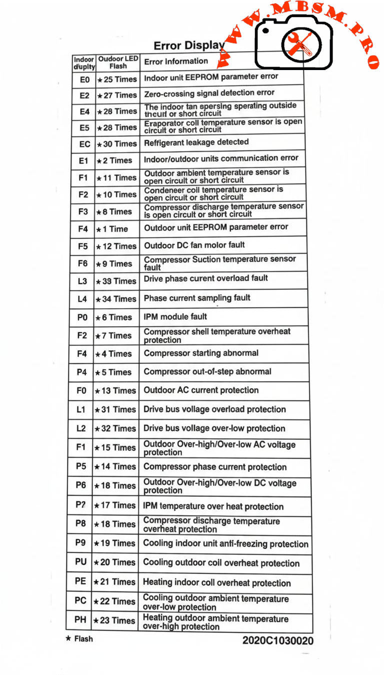
Indoor codes mainly relate to EEPROM parameters, communication, and temperature or refrigerant protection. The table summarizes the key entries from the error‑display list.​

Indoor code Typical description Technical meaning
E0 Indoor unit EEPROM parameter error Configuration data in indoor PCB memory cannot be read or is corrupted.​
E2 Indoor/outdoor units communication error Serial data between indoor and outdoor boards lost or unstable.​
E4 Indoor room or coil temp sensor error Temperature sensor open/short, usually T1 or similar designation.​
E5 Evaporator coil temperature sensor error T2 thermistor fault, affecting frost and overheat protection.
EC Refrigerant leakage detected Control logic detects abnormal combination of coil temperatures and runtime.​
P9 Cooling indoor unit anti‑freezing protection Evaporator temperature too low; system reduces or stops cooling.

Indoor sensor and communication errors often originate from loose connectors, pinched cables, or water ingress around the PCB rather than failed components, so visual inspection is a critical first step.​


Carrier Inverter Outdoor Unit and Power‑Electronics Codes

Outdoor codes in Carrier inverter systems cover ambient and coil sensors, DC fan faults, compressor temperature, current protection, and IPM module errors.​

Code Short description Engineering interpretation
F1 Outdoor ambient temperature sensor open/short T4 thermistor fault; affects capacity and defrost logic.
F2 Condenser coil temperature sensor open/short T3 sensor error; risks loss of condensing control.
F3 Compressor discharge temp sensor open/short T5 failure; system cannot monitor discharge superheat.​
F4 Outdoor EEPROM parameter error PCB memory error in outdoor unit.​
F5 Outdoor DC fan motor fault / speed out of control DC fan not reaching commanded speed; bearing, driver, or wiring issue.​​
F6 Compressor suction temperature sensor fault Suction line thermistor reading abnormal values.
F0 Outdoor AC current protection Abnormal outdoor current over‑high or over‑low; system enters protection mode.​
L1 / L2 Drive bus voltage over‑high / over‑low protection DC bus outside limits, often due to mains issues or rectifier problems.​
P0 IPM module fault Intelligent Power Module over‑current or internal failure; compressor speed control compromised.​
P2 Compressor shell temperature overheat protection Excessive body temperature at compressor top sensor.​
P4 Inverter compressor drive error Drive IC or gate‑signal abnormal; may follow IPM or wiring problems.​
P5 Compressor phase current or mode conflict Phase current protection or logic conflict in operating mode selection.​​
P6 Outdoor DC voltage over‑high/over‑low or IPM protection DC bus or IPM voltage feedback outside safe range.​
P7 IPM temperature overheat protection Inverter module overheating due to high load or blocked airflow.​
P8 Compressor discharge temperature overheat protection Discharge sensor indicates over‑temperature; often linked to poor condenser airflow or charge issues.​
PU / PE / PC / PH Coil or ambient overheat / over‑low protections depending on model Protection of indoor or outdoor coil and ambient sensors during extreme conditions.​

For codes like F0, P0, P1, P6, service manuals stress checking supply voltage, compressor current, and all inverter‑side connections before deciding to replace expensive PCBs or the compressor itself.​


Comparison With LG Inverter Error Logic

Both Carrier and LG inverter systems protect similar components, but the naming and grouping of codes differ slightly.​

Feature Carrier inverter codes LG inverter codes
EEPROM / memory E0 indoor / outdoor EEPROM malfunction.​ 9, 60: indoor/outdoor PCB EPROM errors.
Communication E2 indoor‑outdoor comms error.​ 5, 53: indoor‑outdoor communication errors.
IPM / inverter P0 IPM malfunction, P6 voltage protection, P7 IPM overheat.​ 21, 22, 27: IPM and current faults, 61–62 heatsink overheat.​
Current protection F0 outdoor AC current, P5 phase current, F0 manuals describe overload diagnosis.​ C6, C7, 29: compressor over‑current and phase errors.​

This comparison helps multi‑brand technicians adapt their diagnostic approach while recognizing common inverter‑system failure modes: sensor faults, communication problems, over‑current, and over‑temperature on the IPM and compressor.​


Engineering‑Level Diagnostic Consel for Carrier Inverter AC

Professional troubleshooting of Carrier inverter error codes should follow structured, safety‑oriented steps.​

  • Stabilize power and reset correctly. Disconnect supply, wait for DC bus capacitors to discharge, and then re‑energize to see if transient grid disturbances caused codes like F0, P1, or L1/L2.​
  • Measure, don’t guess. For sensor codes (F1–F3, F6, P8, P9), check thermistor resistance vs temperature and compare to tables in Carrier service manuals before replacing parts.​
  • Check airflow and refrigerant circuit. Overheat protections (P2, P7, P8, PU, PE, PH) frequently point to blocked coils, failed fans, or charge problems rather than electronic failure.​
  • Handle IPM faults carefully. For P0 and P6, confirm all compressor‑to‑IPM connections, inspect for carbonized terminals, and verify correct insulation before deciding whether the IPM module or compressor has failed.​

Following these engineering practices reduces unnecessary part replacement, protects technicians from high DC bus voltages, and helps maintain long‑term reliability of Carrier inverter installations.​

Focus keyphrase (Yoast SEO)
Carrier inverter AC error codes indoor outdoor EEPROM sensor communication IPM module fault F0 P0 P6 bus voltage over high over low professional troubleshooting guide

SEO title
Mbsmpro.com, Carrier Inverter AC, Error Codes E0–PH, Indoor and Outdoor Unit, F0 AC Current, P0 IPM Fault, Bus Voltage Protection, Professional HVAC Guide

Meta description
Comprehensive Carrier inverter AC error‑code guide covering indoor and outdoor EEPROM, sensor, communication, F0 current protection, P0 IPM faults, and bus‑voltage alarms, with engineering‑level troubleshooting tips for HVAC technicians.

Slug
carrier-inverter-ac-error-codes-f0-p0-p6-professional-guide

Tags
Carrier inverter error codes, Carrier AC F0 code, Carrier IPM fault P0, EEPROM parameter error, bus voltage protection, inverter air conditioner troubleshooting, HVAC diagnostics, Mbsmgroup, Mbsm.pro, mbsmpro.com, mbsm

Excerpt (first 55 words)
Carrier inverter air conditioners use detailed error codes to protect the compressor, sensors, and inverter electronics. Codes such as E0, F0, P0, and P6 reveal EEPROM faults, outdoor AC current problems, IPM module errors, and DC bus voltage issues, giving HVAC technicians a clear roadmap for safe, accurate troubleshooting and long‑term system reliability.

10 PDF or technical resources about Carrier inverter AC error codes

  1. Carrier air conditioner error‑code and troubleshooting tables with indoor and outdoor descriptions (E0, F0, P0, P2, etc.).
  2. Carrier AC error‑code list with explanations for F3, F4, F5, P0–P6 and separate outdoor tables.
  3. Carrier split‑inverter AC error‑code video and transcript, detailing meanings for E0–E5, F0–F5, P0–P7 and related protections.​
  4. Carrier service manual describing overload current protection and diagnostics for F0 with decision conditions and test steps.
  5. Carrier mini‑split service documentation covering IPM module errors, bus‑voltage protections, and compressor temperature protections.​
  6. Field‑Masters technical article on F0 error in Carrier split AC, focusing on outdoor current protection causes and fixes.
  7. Carrier indoor error‑code summary for installers and service technicians (EEPROM, sensor, and communication codes).
  8. Knowledge‑base article on IPM module faults explaining inspection of connections, refrigerant level, and when to replace the IPM module.
  9. General inverter error‑code reference for drive boards and IPM protections that parallels Carrier codes, including PH, PL, PU, and over‑current alarms.
  10. External Carrier code lists used by service centers to cross‑reference outdoor unit errors and recommended corrective actions.
Carrier Inverter AC Error Codes, Indoor and Outdoor Protection mbsmpro


Fresh SFW13C1P‑B Split Air Conditioner

Fresh SFW13C1P‑B Split Air Conditioner mbsmpro

Fresh SFW13C1P-B Split Air Conditioner: Technical Label, Specifications, and Error 11.1 Guide

The Fresh SFW13C1P-B split air conditioner is a 1.5 HP cooling‑only indoor unit designed for 220–240 V residential applications, with a cooling capacity around 12,000 BTU/h and R22 refrigerant. Its nameplate also references the diagnostic code ERR 11.1, which technicians commonly associate with serial communication faults between indoor and outdoor units on similar split systems.


Nameplate data overview

The identification label on the Fresh SFW13C1P-B indoor unit groups the key electrical and operating data needed for installation, commissioning, and service.

  • Model family: SFW13C series, 1.5 HP, cooling‑only split air conditioner.
  • Typical application: Small to medium rooms (about 12–18 m² depending on climate and insulation).
  • Refrigerant: R22 on legacy units in this series, with specified maximum operating pressures for high and low sides.

Fresh SFW13C1P-B basic specifications

Parameter Typical value / range Notes
Series / model SFW13C / SFW13C1P-B Smart digital wall‑mounted split. 
Type Split air conditioner, indoor unit Wall hi‑wall design. 
Nominal horsepower 1.5 HP Residential/light‑commercial class. 
Cooling capacity ≈ 12,000 BTU/h Catalog values for 1.5 HP Fresh SFW13C. 
Function Cooling only No heat pump on this variant. 
Refrigerant R22 On older SFW13C inverter range. 
Voltage 220–240 V Single‑phase supply. 
Frequency 50 Hz MEA / Africa grid standard. 
Moisture protection IP24 (indoor casing) Splash‑resistant enclosure category on label. 
Sound pressure level ≈ 39 dB(A) indoor Quiet residential operation. 

Electrical and operating characteristics

The label on the SFW13C1P‑B provides detailed electrical data that help installers size breakers, cables, and protection devices correctly.

  • Rated voltage 220–240 V, 50 Hz single‑phase with electronic inverter control on associated outdoor units in the SIFW/SFW families.
  • Rated and maximum currents are specified (often around 6–8 A running and 20–25 A max), guiding breaker choice and cable sizing.
  • Input power on cooling is in the 1.5 kW class for a 1.5 HP Fresh split, which matches catalog data for SIFW13C‑IP and SFW13C series.

Indicative electrical table for 1.5 HP Fresh SFW13C series

Item Typical value Practical implication
Rated current (cooling) ≈ 6–7 A Used to check running load. 
Maximum current ≈ 25 A Used for MCB / fuse rating margin. 
Rated input power ≈ 1,560 W Helps estimate energy consumption. 
Isolation / protection 25 A marking, IP24 Indoor unit protection coordination. 

ERR 11.1 on Fresh SFW13C1P-B

The nameplate of this indoor unit explicitly lists “ERR 11.1”, indicating that self‑diagnostic communication is part of the design.

  • On many inverter split systems, error 11 or 11.1 corresponds to a serial communication error between indoor and outdoor units (loss or corruption of signal on the interconnecting terminals).
  • Service manuals for comparable brands describe error 11 as forward or reverse transfer serial communication failure, often triggered when the outdoor PCB does not properly receive the indoor control signal for 10 seconds or more.

Typical causes associated with error 11 / 11.1

Possible cause Description Reference behavior
Loose or oxidized interconnecting terminals Poor contact on indoor–outdoor signal cable can interrupt data communication. 
Wrong wiring sequence Reversed communication cores (e.g., terminals 2–3 swapped) lead to serial transfer errors. 
Damaged communication cable Mechanical damage or moisture ingress causes intermittent signal loss. 
PCB failure Indoor or outdoor main board cannot generate or read serial signal. 
External electrical noise Strong interference, bad earthing or voltage dips disturb the serial bus. 

Professional troubleshooting approach

Professional technicians treating a Fresh SFW13C1P‑B that displays ERR 11.1 can follow a methodical process inspired by standard inverter AC service instructions.

  1. Reset and verify supply

    • Isolate power for several minutes, then re‑energize and confirm that error 11.1 reappears under normal load, ruling out a temporary voltage dip.
    • Check mains voltage within 220–240 V and verify correct earthing to reduce electrical noise on the serial line.

  2. Inspect communication wiring

    • Confirm that the communication terminals on indoor and outdoor units are tightened, corrosion‑free, and wired in the manufacturer’s order.
    • Trace the cable path for cuts, joints, or water ingress, replacing suspect lengths with shielded cable where specified.

  3. Measure serial signal

    • Service documentation for similar systems specifies that the AC serial signal between designated terminals should swing within an expected voltage window (for example, 30–130 V AC) during operation; abnormal readings indicate PCB or wiring faults.
    • During measurement, verify that fan motors and relays do not induce excessive noise on the same harness.

  4. Evaluate PCBs and external causes

    • When wiring and supply are correct, error 11.1 persisting usually points to indoor or outdoor controller PCB failure.
    • Before replacing boards, technicians should rule out external causes such as unstable power feeders, undersized generators, or nearby heavy electrical machinery.


User‑oriented best practices

End users operating a Fresh SFW13C1P‑B split unit can reduce the risk of error codes and extend system life by following a few simple best practices derived from documentation of modern Fresh air conditioners.

  • Maintain clean indoor filters to preserve airflow and reduce strain on the refrigeration circuit and electronics.
  • Avoid repeatedly cycling power from the main breaker, as frequent restarts stress inverter components and communication circuits; instead use the remote control for routine on–off operations.
  • If error 11.1 appears repeatedly after a full power reset, contact qualified HVAC service instead of attempting to rewire the communication cable.
Fresh SFW13C1P‑B Split Air Conditioner mbsmpro