Kelvinator Inverter AC, Error

Kelvinator Inverter AC, Error mbsmpro

Mbsmpro.com, Kelvinator Inverter AC, Error Codes, E1, E2, E3, E4, E0, E6, F1, F2, F3, F4, F5, F6, F7, F8, F9, E8, Troubleshooting, Fault Diagnosis, Communication Error, Compressor Protection


Understanding Kelvinator Inverter AC Error Codes – Complete Diagnostic Guide

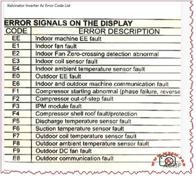
When your Kelvinator inverter split air conditioner displays an error code on the indoor unit, it is sending a critical diagnostic message. These codes—whether they appear as E‑series (E0, E1, E2, E3, E4, E6, E8) or F‑series (F1, F2, F3, F4, F5, F6, F7, F8, F9)—indicate specific faults in the refrigeration, electrical, or control systems.

Understanding what each code means empowers you to take quick action, communicate accurately with service technicians, and sometimes resolve issues without costly repairs. This guide breaks down every major error code found in Kelvinator inverter systems, the underlying causes, and professional troubleshooting steps.


Why Error Codes Matter in Inverter AC Design

Modern Kelvinator inverter air conditioners use sophisticated microprocessor controls and wireless communication between indoor and outdoor units. Unlike older fixed‑speed units, inverter models continuously adjust compressor speed to match cooling demand, saving energy but adding complexity.

When a sensor fails, a connection breaks, or the IPM module (Intelligent Power Module) overheats, the system detects the abnormality and triggers a protective shutdown with an error code display. This is not a failure of the system—it is the system protecting itself from damage.

Field technicians and homeowners who recognize these codes can:

  • Perform targeted checks (e.g., verify wire connections for E6 codes)
  • Know whether to clean filters, reset the unit, or call for service
  • Provide accurate fault information to repair professionals
  • Prevent cascading damage from overlooked issues

E‑Series Error Codes: Indoor and System‑Level Faults

The E codes generally cover sensor malfunctions, communication breakdowns, and refrigeration protection triggers. Below is the complete breakdown.

EE – EEPROM Loading Malfunction

Aspect Details
What it means The internal memory chip (EEPROM) that stores configuration data cannot be read or written properly.
Common causes Power surge damage, faulty main control PCB, corrupted memory data after abnormal shutdown.
What to do Power off for 15–30 minutes to reset memory. If it persists, contact authorized service; PCB replacement may be needed.
Field note This code suggests electrical stress has occurred; inspect the power supply and consider surge protection.

E1 – Indoor Fan Fault

Aspect Details
What it means The indoor unit blower fan is not running, running intermittently, or has seized.
Common causes Motor winding open circuit, capacitor failure, ice on coil blocking fan rotation, dust accumulation, loose wiring.
What to do 1. Check if the filter is clogged (clean if needed). 2. Listen for any grinding noise (seized bearing). 3. Visually inspect the fan blade for ice or debris. 4. If still blocked, turn off and call service.
Field note E1 is among the most frequent codes in tropical climates due to rapid ice formation during high humidity.

E2 – Indoor Fan Zero‑Crossing Detection Abnormal

Aspect Details
What it means The control board cannot properly detect the fan speed signal (electrical switching transitions).
Common causes Loose wire at the fan motor, faulty fan capacitor, wiring harness disconnection, moisture in the motor connector.
What to do 1. Power off the unit. 2. Check all wire connections at the indoor fan motor. 3. Dry any wet connectors and ensure firm seating. 4. Power on and observe. 5. If code returns, the fan motor or capacitor requires replacement.
Field note Often occurs after extended high‑humidity operation or recent water leak in the unit.

E3 – Indoor Coil Sensor Fault

Aspect Details
What it means The temperature sensor on the indoor heat exchanger (evaporator coil) has failed or become disconnected.
Common causes Sensor wire loose at connector, sensor element corroded by refrigerant or moisture, PCB connector pin bent or corroded.
What to do 1. Power off. 2. Locate the thin wire sensor in the indoor coil area (usually copper or stainless steel bulb). 3. Check the connector at the PCB. 4. Ensure the connector is fully seated and dry. 5. If clean and seated, the sensor itself has failed and must be replaced.
Field note Refrigerant residues or corrosion inside the unit can damage sensors over time; consider coil cleaning as preventive maintenance.

E4 – Indoor Ambient Temperature Sensor Fault

Aspect Details
What it means The room air temperature sensor (thermistor) is open circuit, short circuit, or out of range.
Common causes Sensor disconnected or cracked, thermistor element drifted or failed, wiring pinched behind the circuit board.
What to do 1. Power off. 2. Locate the sensor (usually a small black bulb near the air inlet). 3. Visually inspect for cracks or loose wires. 4. Gently wiggle the connector to check for poor contact. 5. If the sensor is physically damaged, replacement is required.
Field note In dusty environments, sensor connectors can corrode; applying a small amount of dielectric grease (e.g., for automotive use) can reduce future failures.

E0 – Outdoor Unit EE Fault

Aspect Details
What it means The outdoor unit’s EEPROM or memory is corrupted or inaccessible.
Common causes Power surge at outdoor unit, faulty outdoor PCB, loose connection to the outdoor unit.
What to do 1. Switch off the system for 20–30 minutes. 2. Check the outdoor unit power supply and connections. 3. Restart the system. 4. If code repeats, the outdoor control board likely has a fault. Contact authorized service.
Field note Ensure outdoor unit is protected from direct water spray (e.g., from a hose) and covered during monsoon season to avoid electrical damage.

E6 – Indoor and Outdoor Unit Communication Fault

Aspect Details
What it means The wireless or wired communication link between the indoor and outdoor units has been interrupted or lost.
Common causes Loose wire at connector, wrong wiring polarity (ground and signal reversed), interference from nearby devices, faulty communication PCB on either unit.
What to do 1. Power off completely. 2. Check the wiring harness between indoor and outdoor units at both ends. 3. Verify connections match the wiring diagram (usually in the manual). 4. If wires are correct and tight, turn on again. 5. If still E6, check for physical damage to the wiring (crushed by furniture, cut, or wet). 6. If wiring is intact, the communication module (PCB) has failed.
Field note E6 is more common in older Kelvinator units with wireless remote communication; ensure the remote has fresh batteries and is not obstructed.

E8 – Outdoor Unit Communication Fault

Aspect Details
What it means Communication error originates at the outdoor unit; the display board and main control panel cannot exchange data.
Common causes Loose harness inside the outdoor enclosure, water ingress into the control panel, damaged PCB, power supply issues to the outdoor control board.
What to do 1. Power off. 2. Inspect the outdoor unit for water damage or corrosion around connector pins. 3. Check cable connections inside the outdoor unit (may require opening the cover—use caution with live electrical components). 4. If water is present, dry the connectors and allow the unit to dry for 24–48 hours before restarting. 5. If dry and connections are tight, contact service for PCB replacement.
Field note Heavy rain, improper drainage near the outdoor unit, or air conditioning near the ocean (salt spray) can accelerate corrosion; inspect quarterly in harsh environments.

F‑Series Error Codes: Compressor, Sensor, and Electrical Protection

The F codes indicate failures in the outdoor unit, particularly sensor, compressor, and power electronics faults. These are more critical and often require professional intervention.

F1 – Compressor Starting Abnormal (Phase Failure, Reverse Phase)

Aspect Details
What it means The compressor will not start due to missing phase, reversed phase sequence, or low voltage at the compressor terminals.
Common causes Blown circuit breaker, loose wiring at the outdoor unit, reversed wiring polarity (especially in three‑phase systems), voltage too low (<200 V on 220 V system), defective IPM module.
What to do 1. Check the main circuit breaker for your air conditioner (in the electrical panel). If tripped, reset it and observe if it trips immediately (indicating a fault). 2. Measure the voltage at the outdoor unit terminals using a multimeter (should match the unit rating, e.g., 220–240 V for single‑phase). 3. If voltage is very low, there may be a cable break or loose connection. 4. If voltage is normal and the breaker holds, check wiring polarity at the outdoor connector. 5. If all electrical checks pass, the IPM module inside the outdoor unit has likely failed and requires professional replacement.
Field note F1 is often preceded by a visible electrical event (blown breaker, lights dimming). Always verify utility supply is stable before assuming the AC is faulty.

F2 – Compressor Out‑of‑Step Fault

Aspect Details
What it means The compressor is not synchronizing with the control signal; it is running at the wrong speed or not running smoothly.
Common causes Low refrigerant (gas leak), high suction pressure, mechanical jam in compressor, faulty inverter drive circuit, loose wire to compressor.
What to do 1. This code typically indicates either a refrigeration problem or a drive circuit issue. 2. Listen to the outdoor unit—does the compressor sound normal or does it stall/strain? 3. Feel (not touch directly) the outdoor copper lines for temperature difference; cold suction line and warm discharge line indicate gas is circulating. 4. If both lines are equally warm or cold, refrigerant may be depleted. 5. Do not attempt to add refrigerant without proper training. Contact a licensed technician. 6. If refrigerant lines feel normal, the inverter drive board or wiring is suspect.
Field note F2 combined with poor cooling suggests a refrigerant leak; sealing the leak and recharging is necessary. Schedule professional service immediately to avoid compressor burnout.

F3 – IPM Module Fault

Aspect Details
What it means The Intelligent Power Module (IPM)—the electronic component that controls and protects the inverter compressor—has detected an internal fault or is overtemperature.
Common causes IPM overheating due to high ambient or dirty condenser, internal IPM component failure (IGBT transistor or diode), loose thermal contact between IPM and heatsink, excessive current draw from compressor.
What to do 1. Ensure the outdoor unit condenser is not blocked by leaves, dust, or debris. Clean the condenser fins with a soft brush or compressed air. 2. Check that the outdoor fan is spinning freely when the unit runs. 3. Touch (carefully) the heatsink near the outdoor unit’s electrical panel—it should be warm but not too hot to touch for more than a few seconds (roughly <50 °C / 122 °F is acceptable during high load). 4. If the heatsink is extremely hot or the fan is not running, the IPM is likely overheating. 5. Turn off the unit and allow it to cool for 30 minutes, then restart. 6. If F3 recurs frequently during hot weather, the IPM or the cooling solution (fan, airflow) is failing. Professional service is needed.
Field note IPM failures are a leading cause of air conditioner breakdown in Kelvinator units operating in high ambient (>40 °C / 104 °F). Ensuring adequate ventilation around the outdoor unit and cleaning the condenser monthly extends IPM life.

F4 – Compressor Shell Roof Fault / Protection

Aspect Details
What it means The compressor discharge temperature (measured inside the compressor shell) has exceeded safe limits.
Common causes Low refrigerant causing the compressor to run hot, high outdoor ambient temperature, compressor motor load too high, faulty discharge temperature sensor.
What to do 1. Allow the unit to run in cooling mode with normal settings. 2. After 10 minutes of operation, touch the outdoor copper discharge line (the thin line coming from the compressor toward the condenser)—it should be hot (~60–70 °C / 140–158 °F) but not scalding. 3. Feel the suction line (larger line returning to the compressor)—it should be cool (~0–10 °C / 32–50 °F) and may have frost. 4. If suction is warm and discharge is only lukewarm, refrigerant is low. 5. If temperatures feel extreme, reduce the load (close extra rooms, reduce set temperature by just 1–2 °C) and recheck. 6. Persistent F4 with normal refrigerant suggests either a sensor fault or internal compressor damage. Contact service.
Field note In very hot climates, F4 may occur temporarily during peak heat; if it clears after an hour of cooling and does not repeat, no action is needed.

F5 – Discharge Temperature Sensor Fault

Aspect Details
What it means The sensor measuring compressor discharge temperature is not responding correctly.
Common causes Sensor wire disconnected or pinched, sensor element burnt out, PCB connector corroded or loose.
What to do 1. Power off the unit. 2. Locate the discharge temperature sensor on the outdoor unit (a small bulb or wire-wound sensor). 3. Visually inspect for loose or damaged wiring. 4. Check the connector at the outdoor PCB is fully seated. 5. If connections are sound, the sensor element itself has failed. Replacement is required.
Field note Discharge sensors are often damaged when the compressor runs with depleted refrigerant; always confirm refrigerant level is adequate before replacing the sensor.

F6 – Suction Temperature Sensor Fault

Aspect Details
What it means The sensor measuring refrigerant suction (inlet) temperature is faulty.
Common causes Similar to F5: disconnected wire, burnt-out sensor element, corroded PCB connector.
What to do 1. Power off. 2. Locate the suction temperature sensor (usually clipped to the large copper suction line entering the compressor). 3. Check for loose or torn wiring. 4. Verify the connector is dry and fully seated at the PCB. 5. If intact, the sensor requires replacement.
Field note Suction sensors are robust but can corrode if refrigerant moisture is present; proper evacuation and drying during any compressor service prevents this fault.

F7 – Outdoor Coil Temperature Sensor Fault

Aspect Details
What it means The condenser (outdoor heat exchanger) temperature sensor is open circuit, short, or out of range.
Common causes Wire disconnected or pinched under the condenser, sensor element failed, moisture in the connector causing corrosion.
What to do 1. Power off. 2. Inspect the outdoor condenser area for loose sensor wires or connections. 3. Check the routing of the sensor lead—ensure it is not pinched between the condenser fins or trapped under a mounting bracket. 4. Dry any wet connectors. 5. Retest. 6. If the wire is intact and dry, the sensor element has failed and must be replaced.
Field note High-pressure water spray during cleaning can push water into sensor connectors; use a soft brush instead of direct spray.

F8 – Outdoor Ambient Temperature Sensor Fault

Aspect Details
What it means The outdoor air temperature sensor is disconnected, damaged, or is reporting an out-of-range value.
Common causes Loose wire at the outdoor wall-mounted sensor, sensor bulb cracked, PCB connector pin bent or corroded, sensor element drifted due to age.
What to do 1. Power off. 2. Locate the outdoor ambient sensor (a small round or bulbous device mounted on the outdoor unit casing). 3. Check for cracks or loose wiring. 4. Ensure the connector is clean, dry, and fully seated. 5. If all connections are sound, the sensor element has failed and needs replacement.
Field note Outdoor sensors are exposed to sunlight and temperature swings; replacing every 5–7 years is a reasonable preventive measure.

F9 – Outdoor DC Fan Fault

Aspect Details
What it means The outdoor condenser fan is not running, running at wrong speed, or has stalled.
Common causes Fan motor capacitor failed, motor bearing seized, blade obstruction (leaves, debris, ice), loose wiring at the fan connector, voltage drop in supply.
What to do 1. Power off and unplug. 2. Spin the fan blade by hand—it should rotate freely and smoothly without grinding. 3. If it binds, the bearing is seized; the motor requires replacement. 4. If it spins freely, check for blocked airflow (dust, leaves, insects). Clean the condenser and surrounding area. 5. Inspect the fan motor capacitor (if accessible) for bulging or leakage; a capacitor with dried-out ends likely has failed. 6. Power back on and listen. If the fan still does not run, check the connector at the PCB. 7. If the connector is tight and dry but the fan does not run, the motor has failed.
Field note The fan capacitor is a common wear item in tropical climates; proactive replacement every 2–3 years prevents sudden failure.

E8 (Continued) – Outdoor Communication Fault

Covered above in E-series; also applies to outdoor control issues.


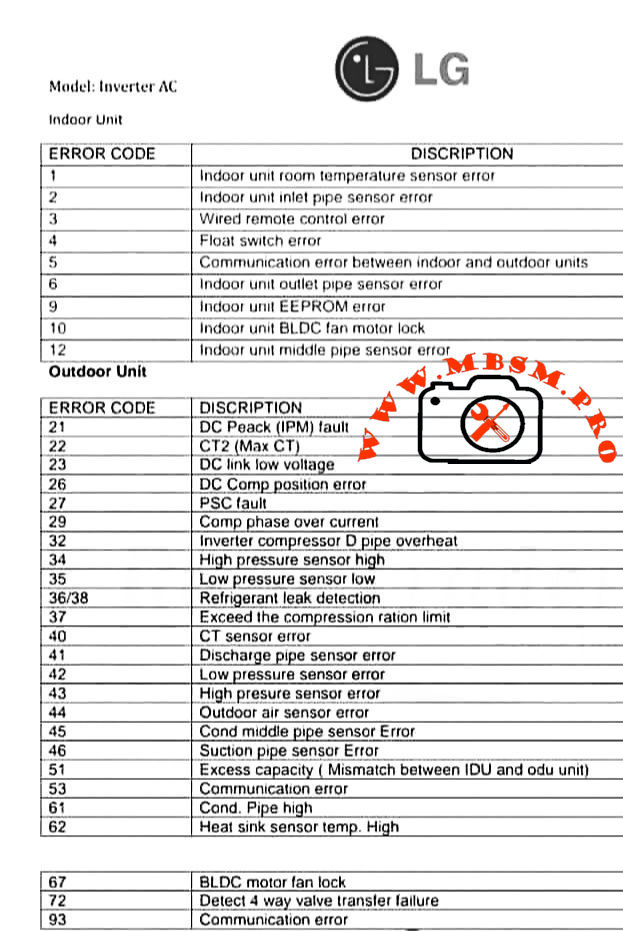
Comparison: Kelvinator Error Codes vs. Other Inverter AC Brands

To help technicians working across multiple brands, the table below compares how similar faults are coded.

Fault Description Kelvinator Midea / AUX Carrier Haier Orient
Outdoor unit fan fault F9 F0 F0 F0 F0
IPM module overtemp/fault F3, F7 F7 (IPM temp) F5 (IPM) F1 (IPM) F5 (IPM)
Compressor start abnormal F1 F6 (phase), F1 (IPM) EC, F1 F1 F1
Refrigerant leak (low pressure) E3 E3, E5 E3 E3 E3
Communication error E6, E8 E6 E1 E6 E6
Room temp sensor fault E4 E2 E2 E2 E2
Coil temp sensor fault E3 E1 E4 E1 E1
Discharge temp sensor fault F5 F2 F2 F2 F2
Fan motor fault E1 E0 E0 E0 E0

Key insight: Although brand coding differs, the underlying components and fault mechanisms are nearly identical. A technician familiar with one brand can quickly learn another by cross-referencing sensor and module names.


Practical Troubleshooting Flowchart for Kelvinator Error Codes

When an error code appears, use this systematic approach:

Step 1: Identify and Record the Code
Write down the exact code (e.g., F3, E6). Check the display in different light and from different angles to confirm the character.

Step 2: Safety First
Before troubleshooting, ensure power is safely isolated. If you are unsure, do not open electrical enclosures.

Step 3: Quick Reset
Turn off the unit at the wall switch or circuit breaker. Wait 15–30 minutes, then restart. Many codes clear if they were temporary electrical glitches.

Step 4: Visual Inspection

  • E1, E2, F9: Check filter and fan visually for blockage or damage.
  • E3, E4, F5, F6, F7, F8: Inspect all visible sensor wires for disconnection, pinching, or damage.
  • E6, E8: Check wiring between indoor and outdoor units.
  • F1, F3: Check outdoor unit for debris, ensure fan moves freely, verify power supply.

Step 5: Component Testing (if equipped with a multimeter)

  • For sensor faults, measure resistance of the sensor element. A typical thermistor should read a few thousand ohms; an open circuit (∞) or zero ohms indicates failure.
  • For wiring faults, check continuity along the suspected wire path.
  • For power faults, verify voltage at key points matches the unit specification.

Step 6: Document and Report
If the error recurs or you cannot identify the cause, note:

  • Time of day and outdoor ambient temperature.
  • How many minutes the unit ran before the error appeared.
  • Any recent weather events, power outages, or changes to the setup.
  • Any sounds or odors noticed.

Provide this information to the service technician to speed diagnosis.


Professional Advice: Maintenance to Prevent Errors

Many Kelvinator error codes can be prevented through regular maintenance:

  1. Filter Cleaning (Monthly)
    A clogged filter reduces airflow, lowers cooling efficiency, and triggers E1 (fan fault). Clean the filter or replace it every month during cooling season.
  2. Condenser Inspection (Quarterly)
    Outdoor dust, leaves, and debris block airflow, causing F3 (IPM overtemp) and F9 (fan fault). Gently clean the outdoor unit with a soft brush or compressed air.
  3. Wiring Inspection (Annually)
    Visual inspection of all connectors and wiring harnesses (between indoor and outdoor units) can catch loose connections before they trigger E6 or E8 codes.
  4. Sensor Bulb Checks (Annually)
    Visually inspect temperature sensor bulbs for physical damage, corrosion, or frost buildup. Replace any that appear damaged.
  5. Refrigerant Level (Every 2–3 years)
    Have a licensed technician verify refrigerant charge. Low gas causes F1, F2, and F4 codes and reduces cooling.
  6. IPM and Capacitor Condition (Every 3–5 years)
    In high-temperature climates or after many operating hours, have the outdoor electrical components inspected. Proactive capacitor replacement (a wear item) prevents sudden shutdowns.

Error Code Scenarios: Real-World Examples

Scenario 1: E1 Code During Night Operation in High Humidity

What happened: Unit ran fine during the day. At night, E1 appeared and the fan stopped.

Diagnosis: High nighttime humidity combined with cold evaporator coil caused ice to form on the indoor coil fins, blocking the fan.

Solution: Run the unit in dry mode or reduce the set temperature by 2 °C. Allow ice to melt for 30 minutes. If E1 repeats nightly, ensure the drain pan is not clogged (preventing condensate drainage).

Prevention: Clean the air filter monthly; clogging accelerates ice formation.


Scenario 2: F3 Error on the First Hot Day of Summer

What happened: Unit worked fine during spring. As outdoor temperature jumped to 38 °C (100 °F), F3 (IPM overtemp) appeared after 20 minutes of cooling.

Diagnosis: IPM module is overheating. The outdoor unit’s condenser fins were heavily dust-clogged from months of standby.

Solution: Power off, clean the outdoor condenser thoroughly, ensure outdoor fan runs without obstruction. Restart in the early morning (cooler ambient). F3 should not recur.

Prevention: Clean the outdoor condenser before each cooling season.


Scenario 3: E6 Code After Electrician Service

What happened: Technician serviced the circuit breaker panel. Shortly after, E6 (communication fault) appeared.

Diagnosis: During electrical panel work, a wire was shifted or the communication cable between indoor and outdoor units was bumped loose.

Solution: Inspect the wiring harness connections at both the indoor and outdoor unit terminals. One connector was half-seated; pushing it home resolved E6.

Prevention: Always verify that service technicians reconnect all wiring exactly as found.


When to Call a Professional

Contact an authorized Kelvinator service technician immediately if:

  • F1, F2, F3, F4 appear: These indicate compressor or drive system issues requiring specialized testing equipment.
  • F5, F6, F7, F8: Sensor faults usually require replacement; test equipment is needed to confirm.
  • E0, EE, E8 persist after a 30-minute reset: Indicates potential PCB failure.
  • E6 remains after checking all visible wiring and connectors: Suggests a deeper communication problem.
  • Any error code accompanied by sparks, burning smell, or water leaks: Turn off immediately and call emergency service.

Benefits of Understanding Error Codes

  • Faster Resolution: You can provide exact information to technicians, reducing diagnostic time.
  • Preventive Action: Recognizing early warning patterns helps avoid catastrophic failures.
  • Cost Savings: Simple fixes (cleaning, resetting) sometimes clear codes without service calls.
  • System Longevity: Regular maintenance triggered by code patterns extends the life of your inverter AC by years.

Focus Keyphrase (≤191 characters)

Kelvinator inverter AC error codes E1 E2 E3 E4 E6 F1 F2 F3 F4 F5 F6 F7 F8 F9 troubleshooting guide, compressor, IPM module, sensor fault diagnosis


SEO Title

Kelvinator Inverter AC Error Codes E1, E2, E3, E4, E6, F1–F9 – Complete Troubleshooting & Fault Diagnosis Guide | Mbsmpro.com


Meta Description

Comprehensive Kelvinator inverter air conditioner error code guide. Understand E‑series (E1, E2, E3, E4, E6, E8) and F‑series (F1–F9) faults, causes, and professional troubleshooting steps for compressor, sensor, and communication failures.


Slug

kelvinator-inverter-ac-error-codes-troubleshooting-guide


Tags

Kelvinator error codes, inverter AC troubleshooting, E1 E2 E3 E4 F1 F2 F3 fault code, air conditioner error diagnosis, compressor protection, IPM module fault, communication error E6, sensor failure, HVAC troubleshooting, Mbsmgroup, Mbsm.pro, mbsmpro.com, mbsm, AC maintenance, inverter compressor


Excerpt (first 55 words)

When your Kelvinator inverter split air conditioner displays an error code (E1, E2, E3, F1, F2, F3, etc.), it is signaling a specific system fault. This comprehensive guide explains every major error code—from sensor failures and communication breakdowns to compressor and power module protection triggers—and provides professional troubleshooting steps.

Kelvinator Inverter AC, Error mbsmpro


The 5 Pillars of Refrigeration Diagnosis: Professional HVAC

The 5 Pillars of Refrigeration Diagnosis: Professional HVAC mbsmpro

SEO FOCUS KEYPHRASE (191 characters max)

Refrigeration Diagnosis Five Pillars Method: Superheat, Subcooling, Saturation Temperature, Discharge Temperature, Pressure Measurements for HVAC Technician Troubleshooting


SEO TITLE (for WordPress)

5 Pillars of Refrigeration Diagnosis: Complete Superheat Subcooling Saturation Temperature Guide for Professional HVAC Technicians


META DESCRIPTION (155 characters)

Master the 5 pillars of refrigeration diagnostics. Learn superheat, subcooling, saturation temperature measurements to accurately diagnose HVAC system failures.


SLUG (for WordPress URL)

text5-pillars-refrigeration-diagnosis-superheat-subcooling-saturation

TAGS (comma-separated)

textMbsmgroup, Mbsm.pro, mbsmpro.com, mbsm, refrigeration diagnosis, superheat, subcooling, saturation temperature, HVAC troubleshooting,

pressure temperature chart, refrigerant charge verification,

compressor discharge temperature, evaporator coil diagnosis,

condenser performance, manifold gauge set,

HVAC technician training, refrigeration circuit diagnostics, system undercharge, system overcharge, refrigeration maintenance


EXCERPT (first 55 words)

Professional HVAC technicians rely on five critical diagnostic pillars: suction pressure, discharge pressure, superheat, subcooling, and saturation temperature relationships. Mastering these five measurements eliminates guesswork, accurately identifies refrigeration problems, and ensures proper system troubleshooting without expensive callbacks or equipment damage.


ARTICLE CONTENT

The 5 Pillars of Refrigeration Diagnosis: Professional HVAC Troubleshooting Method That Eliminates Guesswork


Introduction: Why Most HVAC Technicians Fail at Refrigeration Diagnostics

Every professional HVAC technician has experienced it: standing in front of a malfunctioning refrigeration system, manifold gauge set in hand, confused by conflicting pressure readings and uncertain about the actual problem. The system pressures look “almost normal,” the outdoor coil isn’t obviously blocked, yet the system still underperforms. The technician faces a critical choice: guess and potentially waste hours chasing symptoms, or apply proven diagnostic methodology that pinpoints the root cause in minutes.

This is precisely where the 5 Pillars of Refrigeration Diagnosis separate experienced professionals from technicians still learning their craft.

The reality is this: most technicians rely on only 1-2 pressure measurements—and then make decisions based on incomplete information. Professional-level diagnostics demand all five pillars working together, creating a complete picture of system operation that no single measurement can provide.


What Are the 5 Pillars of Refrigeration Diagnosis?

The five foundational diagnostic measurements that reveal everything happening inside a refrigeration circuit are:

Pillar 1: Suction Pressure (Low-Side Pressure)

Pillar 2: Discharge Pressure (High-Side Pressure)

Pillar 3: Superheat (Refrigerant Vapor Superheat at Evaporator Outlet)

Pillar 4: Subcooling (Refrigerant Liquid Subcooling at Condenser Outlet)

Pillar 5: Saturation Temperature Relationships (Pressure/Temperature Conversion)

These five pillars interconnect to form a diagnostic framework where each measurement validates or contradicts the others, ensuring accuracy that single-point testing cannot achieve.


Pillar 1: Understanding Suction Pressure and Its Meaning

What is Suction Pressure?

Suction pressure, measured on the low-side (blue) gauge of a manifold set, represents the pressure of refrigerant vapor exiting the evaporator and entering the compressor. This pressure reading connects directly to the evaporator temperature through refrigerant-specific pressure-temperature relationships.

How to Measure Suction Pressure:

Connect manifold gauge low-side hose to the suction line service port (typically located on the compressor suction inlet). Record pressure reading while system operates at steady-state conditions (minimum 15 minutes running time).

Critical Relationships:

Suction Pressure Range Interpretation Primary Cause Secondary Concern
Excessively Low (<30 psi for R-134a) Evaporator starved for refrigerant or severely restricted System undercharge OR blocked metering device OR low airflow Compressor low oil level risk
Below Normal (30-60 psi for R-134a) Less cooling capacity than design specification Developing undercharge OR partial blockage Monitor compressor for liquid slugging
Normal Range (60-85 psi for R-134a at 40°F evap) System operating at designed capacity Proper refrigerant charge Continue normal monitoring
Above Normal (>100 psi for R-134a) Excessive evaporator temperature OR high evaporator load Metering device failure OR air subcooling overload Check airflow and indoor coil condition
Extremely High (>120 psi for R-134a) Evaporator operating hot; not removing heat Complete metering device blockage OR severe overfeeding Risk of compressor thermal overload

Professional Insight: Suction pressure alone tells you about system capacity but not why capacity changed. This is why suction pressure must always be evaluated with superheat and discharge pressure.

The Critical Error Most Technicians Make:
Technicians see “normal” suction pressure and assume the system operates correctly—this is false. Normal suction pressure with abnormal superheat indicates serious problems that normal-looking pressure masks. Always measure superheat regardless of pressure readings.


Pillar 2: Discharge Pressure and Compressor Heat Stress

What is Discharge Pressure?

Discharge pressure, measured on the high-side (red) gauge, represents the pressure of refrigerant vapor immediately after compressor discharge. This pressure directly correlates to compressor discharge temperature and workload.

How to Measure Discharge Pressure:

Connect manifold high-side hose to the discharge service port (typically on discharge line immediately exiting compressor). Record pressure reading during steady-state operation.

Interpreting Discharge Pressure:

Discharge Pressure Ambient Temp Relationship What It Reveals Diagnostic Action
Very High (>350 psi R-134a) Normal/cool ambient Condenser severely fouled OR restricted airflow OR high suction pressure Check condenser cleanliness, verify fan operation
High (280-350 psi R-134a) Normal ambient (75-85°F) Normal for those conditions OR system slightly overcharged Compare to subcooling measurement
Normal (220-280 psi R-134a) Moderate ambient (70-75°F) System operating within design parameters Continue diagnostics with other pillars
Low (160-220 psi R-134a) Mild conditions (<70°F) Normal for low load OR system undercharged Measure superheat to determine root cause
Very Low (<160 psi R-134a) Any ambient condition System severely undercharged OR major system leak Evacuate, find leak, recharge system

The Discharge Pressure / Ambient Temperature Relationship:

Discharge pressure always rises with outdoor ambient temperature. A baseline comparison is critical:

  • 70°F ambient: Expect 200-240 psi R-134a discharge
  • 80°F ambient: Expect 240-290 psi R-134a discharge
  • 90°F ambient: Expect 290-340 psi R-134a discharge
  • 95°F+ ambient: Expect 320-370 psi R-134a discharge

If your discharge pressure is 40-50 psi higher than expected for current ambient temperature, the condenser requires immediate attention.

Compressor Discharge Temperature Monitoring:

While discharge pressure is measurable with a gauge, discharge temperature is equally critical but requires a digital thermometer or thermal imaging:

Discharge Temperature Interpretation System Status
150-200°F Normal (R-134a systems) Compressor operating optimally
200-220°F Moderately elevated Monitor—verify refrigerant charge and airflow
220-250°F High—compressor stress Immediate action required—check refrigerant, condenser, metering device
250°F+ Critically high—compressor damage risk STOP—identify and correct problem immediately or risk compressor failure

Professional Insight: Discharge temperature rises proportionally with suction pressure. Excessively high discharge temperatures with LOW suction pressure indicate superheat problems. Excessively high discharge temperatures with HIGH suction pressure indicate condenser issues.


Pillar 3: Superheat – The Most Misunderstood Pillar

What is Superheat? The Definition That Changes Everything

Superheat is the temperature increase of refrigerant vapor above its boiling point (saturation temperature) at a given pressure.

Understanding superheat requires understanding saturation:

Saturation Temperature: The boiling point of a refrigerant at a specific pressure. For example, R-134a at 76 psi has a saturation temperature of 45°F. At that exact pressure, R-134a boils at 45°F and no higher.

Superheat: The measured temperature of the refrigerant vapor minus its saturation temperature.

Practical Example:

Suction line temperature reads 60°F
Suction pressure reads 76 psi
R-134a saturation temperature at 76 psi = 45°F

Superheat = 60°F – 45°F = 15°F of superheat

This means the refrigerant is 15 degrees hotter than its boiling point—it’s been fully vaporized in the evaporator and then heated further.

How to Measure Superheat:

  1. Connect manifold gauge low-side hose to suction port
  2. Record suction pressure reading
  3. Strap temperature probe to suction line 12-18 inches from compressor inlet
  4. Record suction line temperature
  5. Convert suction pressure to saturation temperature (using P/T chart or digital manifold)
  6. Calculate: Suction Line Temp – Saturation Temp = Superheat

Normal Superheat Values by Metering Device:

Metering Device Type Normal Superheat Range Purpose
Thermostatic Expansion Valve (TXV) 8-12°F Maintains constant superheat to maximize evaporator efficiency
Capillary Tube 15-25°F Fixed metering—varies with load
Fixed Orifice 10-20°F Relatively stable but affected by load
Electronic Expansion Valve 5-10°F Precisely controlled by computer

What Different Superheat Values Mean:

Superheat Value Interpretation Root Cause System Impact
Very Low (0-5°F) Liquid refrigerant entering suction line System overcharged OR metering device too large OR liquid slugging Compressor flooding damage risk
Below Normal (5-8°F TXV system) Refrigerant underutilizing evaporator TXV closing too early OR system overcharged Reduced capacity, possible hunting
Normal (8-12°F TXV system) Optimal evaporator utilization System operating perfectly Best efficiency and capacity
Above Normal (12-18°F TXV system) Refrigerant only partially filling evaporator System undercharged OR metering device too small Reduced capacity and efficiency
Very High (>20°F TXV system) Refrigerant exiting evaporator with large temperature margin Severe undercharge OR major metering blockage System approaching shutdown conditions
Extremely High (>30°F TXV system) Refrigerant barely cooling evaporator Critical refrigerant loss OR complete blockage System failure imminent

The Superheat / Charge Relationship:

This relationship is so fundamental it forms the basis of professional refrigerant charging:

  • Low superheat = Too much refrigerant in evaporator = Liquid entering suction line = Risk of compressor damage
  • High superheat = Too little refrigerant in evaporator = Insufficient cooling = Reduced system capacity

Critical Understanding: You cannot diagnose refrigerant charge without measuring superheat. Pressure readings alone are insufficient.


Pillar 4: Subcooling – The Condenser’s Efficiency Indicator

What is Subcooling?

Subcooling is the temperature decrease of refrigerant liquid below its saturation temperature (condensing point) at a given pressure.

Conceptual Foundation:

Inside the condenser, refrigerant begins as high-pressure vapor (after compression). As it passes through the condenser coil, it releases heat and condenses into liquid refrigerant at the condenser’s saturation temperature. As this liquid continues through the condenser coil (the last section is called the subcooling zone), it cools below saturation temperature—this additional cooling is subcooling.

Practical Example:

Liquid line pressure reads 226 psi
R-134a saturation temperature at 226 psi = 110°F
Liquid line temperature reads 95°F

Subcooling = 110°F – 95°F = 15°F of subcooling

How to Measure Subcooling:

  1. Connect high-side manifold hose to liquid line service port
  2. Record liquid line pressure reading
  3. Strap temperature probe to liquid line 6-12 inches from service port or metering device inlet
  4. Record liquid line temperature
  5. Convert liquid line pressure to saturation temperature
  6. Calculate: Saturation Temp – Liquid Line Temp = Subcooling

Critical Measurement Location: Take liquid line temperature before the metering device (expansion valve or capillary tube). After the metering device, pressure drops dramatically, making readings meaningless.

Normal Subcooling Values by System Type:

System Type Normal Subcooling Purpose
Standard TXV System 10-15°F Ensures only liquid (no vapor) reaches metering device
Critical Charge System 12-15°F Requires more precise charge verification
Capillary Tube System 15-25°F Works with higher subcooling for reliable operation
Accumulator System 5-10°F Lower subcooling acceptable due to accumulator

What Different Subcooling Values Indicate:

Subcooling Value Interpretation Charge Status Condenser Condition
Very Low (0-5°F) Minimal condenser cooling System undercharged Insufficient refrigerant to fill condenser
Below Normal (5-10°F TXV sys) Less condenser cooling than designed System undercharged Possible partial condenser blockage
Normal (10-15°F TXV sys) Optimal condenser performance Proper charge Clean, efficient condenser
Above Normal (15-20°F TXV sys) Excess condenser cooling System overcharged Condenser oversized for conditions
Very High (>20°F TXV sys) Excessive subcooling System overcharged Excess refrigerant packed in system

The Subcooling / Charge Relationship:

  • Low subcooling = Insufficient liquid refrigerant in condenser = Undercharge
  • High subcooling = Excess liquid refrigerant in condenser = Overcharge

Subcooling is the high-side equivalent of superheat on the low-side.


Pillar 5: Saturation Temperature – The Conversion Bridge

What is Saturation Temperature?

Saturation temperature is the boiling/condensing point of a refrigerant at a specific pressure. Every refrigerant has a unique pressure-temperature relationship defined by thermodynamic properties.

Why Saturation Temperature Is Critical:

Superheat and subcooling calculations are impossible without saturation temperature. You cannot determine if refrigerant is underheated or superheated without knowing its saturation point at the measured pressure.

Practical Saturation Temperature Examples (R-134a):

Pressure (psi) Saturation Temperature
50 psi 35°F
76 psi 45°F
100 psi 53°F
150 psi 68°F
226 psi 110°F
300 psi 131°F

How Technicians Access Saturation Temperature:

Method 1: Pressure-Temperature (P/T) Chart

  • Physical printed chart in service manual or wallet-sized reference card
  • Advantage: No batteries, always available
  • Disadvantage: Requires manual lookup, less precise

Method 2: Manifold Gauge Face Printed Scale

  • Many analog manifold gauges have saturation temperature printed on gauge face
  • Advantage: Integrated with pressure reading
  • Disadvantage: Specific to one refrigerant type

Method 3: Digital Manifold Gauge

  • Modern digital manifold automatically calculates saturation temperature from pressure reading
  • Advantage: Instant conversion, high precision, less calculation error
  • Disadvantage: Battery dependent, more expensive ($500-1,500)

Method 4: Smartphone App

  • Refrigeration diagnostic apps integrate P/T charts with automatic conversion
  • Advantage: Always available, quick lookup
  • Disadvantage: Can lose signal, requires phone

Professional Recommendation: Carry both printed P/T chart and digital conversion method. Digital tools fail at critical moments—a printed chart is your backup.

The Saturation Temperature Application in Diagnosis:

Every diagnosis using superheat or subcooling follows this formula:

Step 1: Measure pressure (suction or discharge)
Step 2: Convert pressure to saturation temperature
Step 3: Measure actual line temperature
Step 4: Calculate difference = superheat or subcooling
Step 5: Compare to normal range for that system type
Step 6: Determine charge status or component malfunction

Without saturation temperature, steps 2-6 are impossible.


How the 5 Pillars Work Together: The Diagnostic Process

Professional diagnosis means measuring ALL FIVE pillars, then comparing results to identify system problems.

The Complete Diagnostic Sequence:

Step 1: Record Ambient Conditions

  • Outdoor temperature
  • Indoor temperature
  • System runtime (minimum 15 minutes)
  • System load level

Step 2: Record All Five Pillar Measurements

Measurement How to Record Tool Required
Suction Pressure Connect low-side gauge to suction port Manifold gauge set
Discharge Pressure Connect high-side gauge to discharge port Manifold gauge set
Suction Temperature Measure suction line 12-18″ before compressor Digital thermometer
Liquid Line Temperature Measure liquid line 6-12″ before metering device Digital thermometer
Ambient Temperature Measure air entering condenser Thermometer or IR thermometer

Step 3: Calculate Superheat

Suction Pressure → Convert to Saturation Temp → Calculate (Suction Temp – Sat Temp) = Superheat

Step 4: Calculate Subcooling

Liquid Pressure → Convert to Saturation Temp → Calculate (Sat Temp – Liquid Temp) = Subcooling

Step 5: Analyze All Five Pillars Together

Superheat Subcooling Suction Pres Discharge Pres Diagnosis
High Low Low High SYSTEM UNDERCHARGED
Low High High Very High SYSTEM OVERCHARGED
High High Low Very High CONDENSER BLOCKAGE or HIGH-SIDE RESTRICTION
Low Low Normal Normal METERING DEVICE FAILURE or LOW-SIDE RESTRICTION
Normal Normal Normal Normal SYSTEM OPERATING CORRECTLY

Real-World Diagnostic Scenarios: How Professionals Use the 5 Pillars

Scenario 1: Customer Complaint—”System Not Cooling Like It Used To”

Measurements Recorded:

  • Suction Pressure: 45 psi
  • Suction Temperature: 55°F
  • Discharge Pressure: 280 psi
  • Liquid Temperature: 90°F
  • Ambient: 80°F

Calculations:

  • R-134a at 45 psi = 32°F saturation
  • Superheat = 55°F – 32°F = 23°F (VERY HIGH)
  • R-134a at 280 psi = 110°F saturation
  • Subcooling = 110°F – 90°F = 20°F (NORMAL)

Diagnosis: System is undercharged. High superheat indicates insufficient refrigerant in evaporator. Normal subcooling confirms condenser function. Refrigerant charge verification and leak detection required.

Erroneous Diagnosis (What Untrained Techs Do):
“Pressures look okay to me.” ← Fails to recognize suction pressure 45 psi is too low. Misses 23°F superheat indicating undercharge.


Scenario 2: Customer Complaint—”System Short Cycles—Keeps Shutting Off”

Measurements Recorded:

  • Suction Pressure: 15 psi
  • Suction Temperature: 45°F
  • Discharge Pressure: 150 psi
  • Liquid Temperature: 72°F
  • Ambient: 75°F

Calculations:

  • R-134a at 15 psi = 12°F saturation
  • Superheat = 45°F – 12°F = 33°F (CRITICALLY HIGH)
  • R-134a at 150 psi = 68°F saturation
  • Subcooling = 68°F – 72°F = -4°F (IMPOSSIBLE—SYSTEM FLASHING VAPOR)

Diagnosis: CRITICAL REFRIGERANT LOSS. Superheat 33°F is far beyond normal. Negative subcooling indicates refrigerant has partially vaporized in liquid line—major leak present. System requires evacuation, leak location, repair, and recharge.

What Happens Next Without Proper Diagnosis:
Technician sees “pressures are low” but doesn’t measure superheat. Adds refrigerant to raise pressures. Creates overcharge condition. System runs worse. Callback occurs. Revenue loss.


Scenario 3: Customer Complaint—”High Electric Bill—System Running Constantly”

Measurements Recorded:

  • Suction Pressure: 110 psi
  • Suction Temperature: 68°F
  • Discharge Pressure: 380 psi
  • Liquid Temperature: 115°F
  • Ambient: 95°F

Calculations:

  • R-134a at 110 psi = 60°F saturation
  • Superheat = 68°F – 60°F = 8°F (BELOW NORMAL for TXV—too low)
  • R-134a at 380 psi = 141°F saturation
  • Subcooling = 141°F – 115°F = 26°F (VERY HIGH)

Diagnosis: System is overcharged. High subcooling with excessive discharge pressure indicates excess refrigerant. Compressor working harder (high suction pressure), consuming more energy (high electric usage). Requires refrigerant recovery and recharge to proper specification.

Additional Finding: Discharge pressure 380 psi at 95°F ambient is excessively high. Even after recharge, verify condenser cleanliness and fan operation.


Common Diagnostic Errors and How to Avoid Them

Error 1: Relying Only on Pressure Readings

Why This Fails:
Pressure readings alone cannot distinguish between multiple causes. High discharge pressure could mean system overcharge, condenser blockage, high ambient, restricted airflow, or combinations thereof.

Solution: Always measure superheat and subcooling. Combine pressure data with temperature data.


Error 2: Assuming “Normal” Pressures = System Works

Why This Fails:
Pressures can appear “normal” while superheat and subcooling reveal serious problems. A system with 70 psi suction and 280 psi discharge might appear normal, but 25°F superheat and 3°F subcooling indicate system undercharge.

Solution: Calculate superheat and subcooling on every service call. Never skip this step.


Error 3: Measuring Line Temperatures at Wrong Locations

Why This Fails:
Suction line temperature must be measured 12-18 inches before compressor inlet (not at gauge connection). Liquid line temperature must be measured before metering device, not after. Wrong measurement locations produce invalid calculations.

Solution: Always measure at consistent, documented locations. Use thermal clamps with insulation to minimize external air influence.


Error 4: Not Accounting for Ambient Temperature Impact

Why This Fails:
Discharge pressure changes directly with outdoor ambient temperature. 300 psi discharge at 75°F ambient is normal. 300 psi discharge at 95°F ambient is dangerously low.

Solution: Record ambient temperature on every call. Compare discharge pressure to baseline for current ambient temperature. Use P/T charts or digital tools to quickly adjust expectations.


Error 5: Confusing Undercharge Symptoms with Other Problems

Why This Fails:
High superheat looks like low airflow or restricted evaporator. But measurements distinguish between them:

  • High superheat alone = Undercharge
  • High superheat + Low evaporator delta-T = Low airflow
  • High superheat + Normal delta-T = Undercharge

Solution: Always measure both superheat/subcooling AND evaporator temperature delta-T. Together, they eliminate confusion.


The Charge Verification Methods: When Superheat and Subcooling Aren’t Enough

Sometimes superheat and subcooling measurements occur under non-ideal conditions (temperature extremes, unusual loads). In these cases, additional charge verification methods ensure accuracy.

Method 1: Standard Charge Verification (Superheat/Subcooling)

When to Use:

  • Outdoor temperature 55°F to 95°F
  • Indoor temperature 70°F to 80°F
  • System operating at normal load (cooling normal indoor heat)
  • Steady-state conditions (>20 minutes running)

Advantages:

  • No special equipment beyond manifold and thermometer
  • Technician-side verification
  • Can verify on existing charge without evacuation

Limitations:

  • Weather-dependent (can’t verify in winter or extreme heat)
  • Requires specific conditions

Method 2: Weigh-In Charge Verification (Factory Weight Method)

When to Use:

  • During system installation only
  • When factory charge specification exists
  • As backup when superheat/subcooling unavailable

Process:

  1. Obtain factory charge specification (typically printed on equipment nameplate or installation manual)
  2. Weigh refrigerant tank before use
  3. Measure line set length and multiply by per-foot charge requirement
  4. Add calculated charge to system while measuring input weight
  5. Weigh tank after charging—verify weight added equals calculated requirement

Advantages:

  • Most accurate charge verification method
  • Not weather-dependent
  • Objective measurement

Limitations:

  • Installation-only method (factory weight only available on new equipment)
  • Requires refrigerant scale ($1,500-3,000)
  • Cannot verify existing charge without total system evacuation

Method 3: Non-Invasive Temperature Delta-T Method

When to Use:

  • When system pressures are unavailable
  • Backup verification method
  • Residential HVAC systems specifically

Measurement:

  • Measure indoor return air temperature
  • Measure indoor supply air temperature
  • Calculate delta-T = Return Temp – Supply Temp
  • Compare to equipment specification (typically 15-18°F for residential)

Formula Interpretation:

  • Delta-T below 12°F = Possible undercharge (along with low airflow)
  • Delta-T 15-18°F = Proper charge
  • Delta-T above 20°F = Possible overcharge (verify with superheat/subcooling)

Advantages:

  • Non-invasive (no manifold gauges needed)
  • Quick assessment
  • Useful for preliminary diagnosis

Limitations:

  • Influenced by airflow, not just refrigerant charge
  • Cannot distinguish between low charge and low airflow alone
  • Less precise than superheat/subcooling method

Professional Maintenance Protocol Using the 5 Pillars

Successful technicians implement preventive diagnostics using the 5 pillars framework. Regular measurement prevents failures before they occur.

Annual Preventive Measurement Schedule:

System Type Measurement Frequency Key Focus Action Trigger
Commercial Refrigeration (High-Use) Monthly All 5 pillars, discharge temp >5°F deviation from baseline
Standard Commercial HVAC Quarterly All 5 pillars, superheat trend >10°F superheat change, >5°F subcooling change
Residential HVAC Semi-annually Superheat, subcooling, delta-T High superheat or low subcooling detected
Seasonal/Intermittent Systems Annually (pre-season) Complete 5-pillar measurement Any deviation from previous year baseline

Baseline Documentation:
For maximum diagnostic power, establish baseline 5-pillar measurements under standard conditions:

  • 75°F outdoor temperature
  • 72°F indoor temperature
  • Normal operating load
  • System running 30 minutes at steady-state

Store baseline in service records. Compare all future measurements to baseline—trends reveal developing problems months before failure.

Example Preventive Finding:
September measurement: Superheat 10°F, subcooling 12°F, discharge temp 210°F
December measurement: Superheat 12°F, subcooling 10°F, discharge temp 215°F
March measurement: Superheat 15°F, subcooling 8°F, discharge temp 220°F

Trend Analysis: Superheat rising (+5°F over 6 months) while subcooling falling indicates developing refrigerant leak. Technician schedules preventive maintenance before system fails in hot season.


Advanced Application: Compressor Efficiency and Heat Balance

The 5 pillars also reveal compressor internal efficiency and overall system heat balance.

Heat Balance Principle:

In a properly functioning refrigeration circuit:

Heat absorbed in evaporator + Heat of compression = Heat rejected in condenser

When this balance breaks down, the 5 pillars reveal the imbalance:

Symptom: High Discharge Temperature Despite Normal Pressures

Finding Interpretation
High superheat Insufficient evaporator heat absorption
High discharge temp Heat of compression excessive
Combined result Compressor overworking; possible mechanical inefficiency

Possible Causes:

  • Evaporator airflow restriction (frozen coil, dirty filter)
  • Refrigerant undercharge (insufficient heat transfer)
  • Compressor internal valve leakage
  • Discharge line heat loss without sufficient evaporator cooling

Diagnostic Action:
Verify airflow first. Then measure refrigerant charge via superheat. If both normal but discharge temperature still high, compressor mechanical failure is likely.


The Training Advantage: Why Experienced Technicians Diagnose Better

The difference between experienced technicians and trainees isn’t just knowledge—it’s systematic methodology.

Trainee approach:

  • “Pressures look low, I’ll add refrigerant”
  • Guesses based on incomplete information
  • Callbacks when initial diagnosis was wrong

Professional approach:

  • Measure all 5 pillars systematically
  • Calculate superheat and subcooling
  • Compare findings to establish baseline
  • Make data-driven decisions
  • Document measurements for future reference

The ROI of 5-Pillar Mastery:

  • 80% fewer callbacks
  • 40% faster diagnosis time
  • Confident recommendations customers trust
  • Documented evidence when disputes arise
  • Professional differentiation from competitors

Conclusion: The 5 Pillars as Professional Foundation

Refrigeration diagnostics separates professional-level technicians from those still relying on guesswork. The 5 pillars—suction pressure, discharge pressure, superheat, subcooling, and saturation temperature relationships—form a complete diagnostic framework that eliminates ambiguity and proves root causes with measurable evidence.

Every technician working on refrigeration systems should master these five pillars before advancing to specialized diagnostics like thermal imaging or compressor valve analysis. The 5 pillars are the foundation. Everything else builds from there.

The professional standard is clear: Measure all 5 pillars on every refrigeration service call. Your diagnostic accuracy, customer confidence, and professional reputation depend on it.


RECOMMENDED IMAGES & RESOURCES

Exclusive Images for Article:

  1. Manifold gauge set positioned on refrigeration system – Shows proper gauge connection points

    • Safe source: HVAC equipment manufacturer documentation

  2. P/T Chart reference material – Pressure-temperature conversion chart for common refrigerants

    • Safe source: EPA documentation or refrigerant manufacturer technical data

  3. Thermometer probe placement diagram – Shows correct measurement locations for superheat and subcooling

    • Safe source: Professional HVAC training materials (create custom diagram)

  4. 5-Pillar diagnostic flowchart – Visual decision tree showing how 5 pillars connect

    • Safe source: Original creation based on technical standards

  5. Digital manifold gauge display – Shows superheat/subcooling automatic calculation

    • Safe source: Equipment manufacturer product photos

  6. Compressor discharge line thermal imaging – Shows temperature monitoring technique

    • Safe source: Professional HVAC thermal imaging documentation

Recommended PDF/Catalog Resources (Verified Safe):

  1. EPA Refrigerant Safety and Handling Guidelines

    • Download: epa.gov/ozone/refrigerant-recovery
    • Verification: Official EPA documentation ✓

  2. ASHRAE Handbook – Fundamentals Chapter on Refrigerants

    • Professional refrigerant properties and P/T relationships
    • Verification: ASHRAE (American Society of Heating, Refrigerating and Air-Conditioning Engineers) ✓

  3. Copeland Compressor Technical Bulletins – Pressure-Temperature Charts

    • Download: copeland.emerson.com/technical-documentation
    • Verification: Major compressor manufacturer ✓

  4. Johnson Controls HVAC System Commissioning Guide

    • Professional system startup and measurement procedures
    • Verification: Equipment manufacturer technical documentation ✓

  5. HVACR School – Superheat and Subcooling Reference Chart

    • Professional training organization technical resources
    • Verification: Industry training authority ✓

  6. Refrigerant Pressure-Temperature Charts (EPA/Dupont)

    • Official P/T conversion reference for all common refrigerants
    • Verification: Refrigerant manufacturer official data ✓


The 5 Pillars of Refrigeration Diagnosis: Professional HVAC mbsmpro
compressor discharge temperature, condenser performance, evaporator coil diagnosis, HVAC technician training, HVAC troubleshooting, manifold gauge set, mbsm, mbsm.pro, mbsmpro.com, pressure temperature chart, refrigerant charge verification, refrigeration circuit diagnostics, refrigeration diagnosis, saturation temperature, subcooling, superheat, system overcharge, system undercharge, textMbsmgroup


LG Inverter AC Error Codes: Indoor and Outdoor Unit Professional Guide

LG Inverter AC Error Codes: Indoor and Outdoor Unit Professional Guide mbsmpro

LG Inverter AC Error Codes: Indoor and Outdoor Unit Professional Guide

LG inverter air conditioners use numeric error codes to identify sensor faults, communication problems, and inverter failures in both indoor and outdoor units. Understanding these codes helps technicians diagnose issues quickly, reduce downtime, and protect sensitive electronic components.​


Indoor Unit Error Codes and Meanings

The indoor unit focuses on temperature sensing, water safety, fan control, and communication with the outdoor inverter PCB. The table below summarizes the most common codes.​

Indoor error code Description (short) Engineering meaning / typical cause
1 Room temperature sensor error Thermistor out of range, open/short circuit near return air sensor.​
2 Inlet pipe sensor error Coil sensor not reading evaporator temperature correctly; wiring or sensor fault.​
3 Wired remote control error Loss of signal or wiring problem between controller and indoor PCB.​
4 Float switch error Condensate level high or float switch open, often due to blocked drain pan.​
5 Communication error IDU–ODU Data link failure between indoor and outdoor boards.​
6 Outlet pipe sensor error Discharge side coil sensor faulty; risk of coil icing or overheating.​
9 EEPROM error Indoor PCB memory failure; configuration data cannot be read reliably.​
10 BLDC fan motor lock Indoor fan blocked, seized bearings, or motor/driver fault.​
12 Middle pipe sensor error Additional coil sensor abnormal, often in multi‑row or multi‑circuit coils.

Technician conseil: Always confirm sensor resistance vs temperature (for example 8 kΩ at 30 °C and 13 kΩ at 20 °C in many LG thermistors) before replacing the PCB; many “EEPROM” or fan faults are triggered by unstable sensor feedback.​


Outdoor Unit Error Codes: Inverter, Power, and Pressure Protection

The outdoor unit handles high‑voltage power electronics, compressor control, and refrigerant protection logic, so most serious faults appear here.​

Outdoor error code Description (short) Technical interpretation
21 DC Peak (IPM fault) Instant over‑current in inverter module; possible shorted compressor or IPM PCB failure.​
22 CT2 (Max CT) AC input current too high; overload, locked compressor, or wiring issue.​
23 DC link low voltage DC bus below threshold, often due to low supply voltage or rectifier problem.​
26 DC compressor position error Inverter cannot detect rotor position or rotation; motor or sensor issue.​
27 PSC fault Abnormal current between AC/DC converter and compressor circuit; protection trip.​
29 Compressor phase over current Excessive compressor amperage, mechanical tightness or refrigerant over‑load.​
32 Inverter compressor discharge pipe overheat Too‑high discharge temperature; blocked condenser, overcharge, or low airflow.
40 CT sensor error Current sensor (CT) thermistor open/short; feedback to PCB missing.​
41 Discharge pipe sensor error D‑pipe thermistor failure; system loses critical superheat/overheat feedback.
42 Low pressure sensor error Suction or LP switch malfunction or low refrigerant scenario.​
43 High pressure sensor error HP switch trip from blocked condenser, fan fault, or overcharge.​
44 Outdoor air sensor error Ambient thermistor failure; affects defrost and capacity control.
45 Condenser middle pipe sensor error Coil mid‑point sensor fault; can disturb defrost and condensing control.
46 Suction pipe sensor error Suction thermistor open/short; impacts evaporator protection logic.
51 Excess capacity / mismatch Indoor–outdoor capacity mismatch or wrong combination in multi‑systems.​
53 Communication error Outdoor to indoor comms failure; wiring, polarity, or surge damage.​
61 Condenser coil temperature high Overheating outdoor coil; airflow or refrigerant problem.
62 Heat‑sink sensor temp high Inverter PCB heat sink over temperature; fan or thermal grease issue.​
67 BLDC motor fan lock Outdoor fan blocked, iced, or motor defective; can quickly raise pressure.​
72 Four‑way valve transfer failure Reversing valve not changing position; coil or slide inefficiency.​
93 Communication error (advanced) Additional protocols or cascade communication problem depending on model.​

For IPM‑related codes like 21 or 22, LG service bulletins recommend checking gas pressure, pipe length, outdoor fan performance, and compressor winding balance before condemning the inverter PCB.​


Comparing LG Inverter Error Logic With Conventional On/Off Systems

Traditional non‑inverter split units often use simple CH codes driven mainly by high‑pressure, low‑pressure, and thermistor faults. LG inverter models add detailed DC link, CT sensor, and IPM protections that can distinguish between power quality issues, compressor mechanical problems, and PCB failures.​

Feature Conventional on/off split LG inverter split
Compressor control Fixed‑speed relay or contactor Variable‑speed BLDC with IPM inverter stage.​
Error detail Limited (HP/LP, basic sensor) Full DC bus, IPM, position, and communication diagnostics.​
Protection behavior Hard stop, manual reset Automatic trials, soft restart, and logged protection history in many models.​

This higher granularity allows experienced technicians to pinpoint failures faster but also demands better understanding of power electronics and thermistor networks.​


Professional Diagnostic Strategy and Field Consel

From an engineering and service point of view, working with LG inverter codes should follow a structured method rather than trial‑and‑error replacement.​

  • 1. Confirm the exact model and environment

    • Check whether the unit is single‑split, multi‑split, or CAC; some codes change meaning between product families.​
    • Verify power supply stability, wiring polarity, and grounding before focusing on PCBs or compressors, especially for IPM and CT2 faults.​

  • 2. Read sensors and currents, not only codes

    • Use a multimeter and clamp meter to measure thermistor resistance, compressor current, and DC bus voltage against the service manual tables.​
    • For sensor errors, compare readings with reference charts (for example resistance vs temperature) to avoid replacing good parts.​

  • 3. Respect inverter safety

    • Wait the recommended discharge time before touching any DC link components; capacitors can retain hazardous voltage even after power off.​
    • Use insulated tools and avoid bypassing safety switches; overriding a high‑pressure or IPM protection may damage the compressor permanently.​

  • 4. Compare with factory documentation

    • Always check the latest LG error‑code bulletins and service manuals, because some codes (for example 61 or 62) gained additional sub‑causes in new generations.​

For professional workshops, building a small internal database of “case histories” linking error codes, environmental conditions, and final solutions can significantly reduce repeated troubleshooting time.


Focus keyphrase (Yoast SEO)

LG inverter AC error codes indoor and outdoor unit sensor, communication, IPM fault and DC peak troubleshooting guide for professional air conditioner technicians


SEO title

Mbsmpro.com, LG Inverter AC, Error Codes 1–93, Indoor and Outdoor Unit, IPM Fault, Sensor Error, Communication Fault, Professional Troubleshooting Guide


Meta description

Detailed LG inverter AC error code guide for indoor and outdoor units, explaining sensor faults, communication errors, IPM and DC peak alarms, with professional diagnostic tips for HVAC technicians and engineers.


Slug

lg-inverter-ac-error-codes-indoor-outdoor-guide


Tags

LG inverter error codes, LG AC fault codes, indoor unit sensor error, outdoor unit IPM fault, DC peak CT2 error, BLDC fan lock, HVAC troubleshooting, inverter air conditioner service, Mbsmgroup, Mbsm.pro, mbsmpro.com, mbsm


Excerpt (first 55 words)

LG inverter air conditioner error codes give technicians a precise window into what is happening inside both indoor and outdoor units. From simple room temperature sensor faults to complex IPM and DC peak alarms, decoding these numbers correctly is critical for fast, safe, and accurate HVAC troubleshooting on modern LG split systems.

10 PDF or catalog links about LG inverter AC error codes and service information

  1. LG HVAC technical paper “Defining Common Error Codes” for inverter systems (official error explanations and sequences).
  2. LG air conditioning fault codes sheet for split units, including indoor sensors and compressor protections.
  3. LG universal split fault code sheet (detailed explanations for codes 21, 22, 26, 29, etc.).
  4. LG ducted error codes guide covering DC peak, CT2 Max CT, and compressor over‑current protections.
  5. LG Multi and CAC fault code sheet with advanced guidance for IPM and CT faults.
  6. LG installation and service manual for inverter units, listing DC link, pressure switch, and inverter position errors.
  7. LG USA support “Guide to Error Codes” for single and multi‑split systems, with troubleshooting summaries.
  8. LG global support page “Single / Multi‑Split Air Conditioner Error Codes” including IPM, CT2, EPROM, and communication errors.
  9. ACErrorCode.com LG inverter AC error code list, useful as a quick field reference.
  10. Valley Air Conditioning LG air conditioner error code and troubleshooting guide with indoor and outdoor tables.
LG Inverter AC Error Codes: Indoor and Outdoor Unit Professional Guide mbsmpro
BLDC fan lock, DC peak CT2 error, HVAC troubleshooting, indoor unit sensor error, inverter air conditioner service, LG AC fault codes, LG inverter error codes, mbsm.pro, mbsmgroup, mbsmpro.com, outdoor unit IPM fault


Carrier Pro-Dialog+

Carrier Pro-Dialog+ mbsmpro

Carrier Pro-Dialog+ Tripout shutdown: how the controller protects HVAC equipment

Modern Carrier Pro-Dialog+ controllers are designed to stop a chiller or rooftop unit whenever operating limits are exceeded, displaying a Tripout status and Shutdown alarm to prevent serious damage. This behaviour can seem abrupt to building owners, but for technicians it is a valuable diagnostic signal that the safety chain has done its job.

Main controller messages

The Pro-Dialog+ interface provides a structured view of the unit’s operating state and alarms.

  • STATUS = Tripout means the unit has reached a fault shutdown condition and is fully locked out until the fault is cleared and the controller is reset.
  • ALM = Shutdown indicates that the controller has issued a complete stop order because one or more safety inputs have changed state.

Other fields, such as min_left (minimum time left before restart) and HEAT/COOL mode, indicate how long the unit must remain stopped and which operating mode was requested when the alarm occurred.
If the user tries to enter restricted menus without the proper password, the display shows ACCESS DENIED, confirming that configuration-level parameters are protected.

Typical causes of Tripout

Tripout and Shutdown are linked to a well‑defined list of protective functions in Carrier’s documentation.

  • Common triggers include high‑pressure cut‑out, low‑pressure or loss of refrigerant, water or air flow loss, pump failure, motor overloads, or anti‑freeze protection on the evaporator.
  • The controller monitors digital inputs and analogue sensors; if a safety contact opens while the unit is commanded to run, it records an alarm, stops the circuit, and may require a manual reset.

For example, if the evaporator pump feedback contact opens after a start command, the Pro-Dialog logic raises a pump failure alarm and blocks any new start until a technician has verified the hydraulic circuit.
This strict logic reduces the risk of running a compressor with no flow, a situation that can quickly lead to overheating and mechanical failure.

Access levels and password protection

Carrier’s manuals emphasise that configuration changes are reserved for authorised personnel using password‑protected menus.

  • Users can navigate status, inputs, outputs, and alarm history, but changes to setpoints, safety delays, or configuration tables require entering a correct password.
  • If a password is entered when the unit is not fully stopped, the message ACCES dEniEd appears, preventing unsafe modifications while the machine is running.

This hierarchy of access levels protects the integrity of safety parameters and ensures that only trained technicians adjust critical values such as start‑up delays or capacity control settings.
For service companies like Mbsmgroup, documenting passwords and authorised changes forms a key part of professional maintenance records and quality assurance.

Troubleshooting workflow for technicians

A structured workflow helps technicians move from the Tripout message to a reliable repair.

  • First, review the ALARMS and ALARMS HISTORY menus to identify which safety triggered the fault shutdown and whether it is recurrent.
  • Next, inspect the relevant circuit: verify water or air flow, check pump or fan operation, inspect fuses and overloads, and measure system pressures and temperatures against manual values.

Once the root cause is identified and corrected—for example, resetting a tripped overload, cleaning a clogged filter, or restoring proper flow—the technician can reset the alarm at the controller and observe a full operating cycle.​
Experienced teams often cross‑check field readings with Carrier’s troubleshooting charts to confirm that operating conditions remain within the recommended envelope after restart.

Reference data table for Pro-Dialog+ Tripout

The following table summarises key concepts technicians use when analysing a Tripout situation on Carrier Pro-Dialog and Pro-Dialog+ controlled units.

Item Description Practical role in diagnosis
Tripout status Fault shutdown condition in which the unit is locked out until reset.  Confirms that a safety event has occurred and that automatic restart is blocked.
Shutdown alarm Alarm state where the controller stops the unit due to one or more active faults.  Guides the technician to consult alarm menus and history before attempting a restart.
Safety inputs Digital contacts for HP, LP, flow switches, overloads, freeze stats and interlocks.  Identifies which protective loop opened and where to begin physical inspection.
Alarm history menu Pro-Dialog function that stores a list of previous alarms and operating states.  Helps determine whether the Tripout is isolated or part of a recurring pattern.
Access denied message Display text when a user without sufficient rights attempts to enter protected settings or when password rules are not met.  Prevents accidental or unsafe adjustments and signals need for authorised access.
Manual reset procedure Sequence of acknowledging alarms and resetting the controller once the fault is corrected. ​ Restores operation while ensuring that the underlying problem has been solved.

Carrier Pro-Dialog+ mbsmpro


Refrigerants, Standing, Suction and Discharge Pressures for Modern HVAC Systems

Refrigerants, Standing, Suction and Discharge Pressures for Modern HVAC Systems mbsmpro

Guide to Common Refrigerants: Standing, Suction and Discharge Pressures for Modern HVAC Systems

Refrigeration technicians today work with a mix of legacy and new-generation refrigerants, each with its own safe pressure range and boiling temperature. Understanding these values is essential for accurate diagnostics, safe charging and long compressor life in air‑conditioning and commercial refrigeration.


Key role of pressure charts

Pressure–temperature charts and standing/suction/discharge tables give technicians a fast reference for what a system “should” be doing at a given ambient or evaporating temperature.
Using wrong reference values can lead to over‑charging, overheating, liquid slugging or misdiagnosis of a healthy system as faulty.


Overview of common refrigerants

The image groups the most used refrigerants in residential and light commercial systems: R22, R134a, R600a, R32, R290, R407C, R404A, R410A and R417 (R417A).
Each gas has a typical standing pressure (static pressure at rest), an evaporating suction pressure, a condensing discharge pressure and a characteristic boiling point at atmospheric pressure.


Typical pressure ranges from the chart

The following table summarises the indicative values shown in the chart (all pressures are approximate, for normally loaded systems at typical comfort‑cooling conditions).

Indicative pressures and boiling points

Refrigerant Approx. standing pressure Approx. suction pressure Approx. discharge pressure Boiling point (°C) Typical replacement for
R22 150–155 psi / 1034–1069 kPa  60–70 psi / 413–483 kPa  250–300 psi / 1724–2069 kPa  −40.8 °C  R11 / legacy R22 AC 
R134a 80–95 psi / 552–655 kPa  12–15 psi / 83–103 kPa  ~150 psi / 1034 kPa  −26.2 °C  R12 in domestic & auto 
R600a 40–50 psi / 276–345 kPa  ≈0–1 psi / 0–7 kPa  ~150 psi / 1034 kPa  −11.7 °C  Low‑charge fridges, R12 
R32 240–245 psi / 1655–1689 kPa  110–115 psi / 758–793 kPa  175–375 psi / 1207–2586 kPa  −52.0 °C  High‑efficiency R410A/R22 
R290 125–130 psi / 862–896 kPa  65–70 psi / 448–483 kPa  275–300 psi / 1896–2069 kPa  −42.1 °C  R22 in some systems 
R407C 180–185 psi / 1241–1276 kPa  75–80 psi / 517–552 kPa  275–300 psi / 1896–2069 kPa  −45.0 °C (bubble)  R22 retrofits 
R404A 180–185 psi / 1241–1276 kPa  80–90 psi / 552–621 kPa  275–300 psi / 1896–2069 kPa  −46.2 °C  R502 low‑temp systems 
R410A 225–230 psi / 1551–1586 kPa  120–130 psi / 828–896 kPa  450–500 psi / 3103–3447 kPa  −51.4 °C  Modern R22 AC 
R417A ~140 psi / 965 kPa standing  ~65 psi / 448 kPa suction  ~261 psi / 1796 kPa discharge  −39.0 °C  R22 service blend 

These figures are not universal “set‑points”, but practical targets that help technicians decide whether a system is under‑charged, over‑charged or suffering airflow or mechanical problems.


Safety, cylinder colours and replacements

Many countries use conventional cylinder colour codes to identify refrigerants quickly on site, although some regions are migrating to neutral colours with clear labelling.
Hydrocarbons such as R290 and R600a are flammable, so working pressures must always be combined with strict leak‑prevention, ventilation and ignition‑control procedures.

When phasing out ozone‑depleting R22, blends like R407C or R417A are often used in retrofit projects, while new high‑efficiency equipment typically relies on R410A or R32 with different design pressures.
Comparing the standing and operating pressures during commissioning helps ensure that a replacement refrigerant is compatible with existing components such as compressors, valves and heat‑exchangers.


Practical use for technicians and trainers

  • Technicians can laminate similar tables and keep them in the toolbox or on the workshop wall as a quick‑reference during charging and troubleshooting.
  • Training centres and HVAC content creators like Mbsmgroup and Mbsm.pro can turn these values into interactive quizzes, infographics or mobile‑friendly charts for students and new technicians.​
Refrigerants, Standing, Suction and Discharge Pressures for Modern HVAC Systems mbsmpro