LM317 Voltage Regulator: Complete Guide, Pinout, Application Circuit, and Engineering Best Practices
Professional, practical, and ready for WordPress publication — engineered for technicians, makers, and design engineers.
Overview
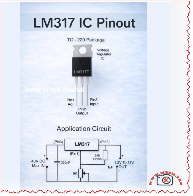
The LM317 is a versatile adjustable linear voltage regulator in a TO‑220 (and SMD) package that delivers a stable output from 1.2 V to 37 V with a maximum input rating of 40 V DC. It’s widely used for bench power supplies, embedded systems, and analog rails where simplicity, low noise, and predictable behavior matter. This article explains pinout and application circuits, common design mistakes, thermal calculations, layout rules, comparisons with alternatives, and practical installation advice.
Pinout and Basic Application
| Pin | Label | Function |
|---|---|---|
| 1 | Adj | Adjust input for output set resistor network |
| 2 | Out | Regulated output voltage |
| 3 | In | Unregulated input voltage (max 40 V DC) |
Typical application components: 240 Ω resistor between Out and Adj, adjustable resistor (e.g., 5 kΩ) between Adj and ground, 330 nF on Adj for stability in some layouts, and 1 µF on Output for transient suppression.
Standard Application Formula
- Output voltage:
where , R1 = 240 Ω, R2 is the adjustable resistor.
Recommended Component Values
| Component | Recommended Value | Purpose |
|---|---|---|
| R1 | 240 Ω | Sets reference current |
| R2 | variable 0–5 kΩ | Sets VOUT range |
| Cadj | 330 nF (optional) | Improves transient response and stability |
| Cout | 1 µF low‑ESR | Output decoupling and stability |
| Cin | 10 µF (electrolytic) | Input decoupling and transient handling |
Thermal Design and Power Dissipation
- Power dissipation:
.
- Example: VIN = 24 V, VOUT = 5 V, ILOAD = 0.8 A → . 15.2 W requires a substantial heatsink or a switching alternative.
Practical rule: If W, plan a heatsink or consider a switching regulator. For portable or battery systems, prefer switching converters for efficiency.
Common Mistakes and How to Fix Them
| Mistake | Effect | Fix |
|---|---|---|
| No input/output decoupling | Oscillation, noise | Add 10 µF on input, 1 µF on output, plus 0.1 µF ceramic close to pins |
| Long traces to caps | Instability | Place caps within 5 mm of pins; use wide traces |
| Ignoring thermal dissipation | Overheating, thermal shutdown | Calculate ; add heatsink or switch to buck converter |
| Wrong capacitor type | Oscillation or poor transient | Use low‑ESR electrolytic or tantalum; pair with ceramic |
| Using LM317 for large VIN–VOUT | Excessive wasted heat | Use buck converter for large drops or high current |
| No protection against reverse input | Device failure on faults | Add diode from Out to In and input transient protection |
Layout and PCB Best Practices
- Place input and output capacitors as close as possible to the regulator pins.
- Use wide copper pours for VIN and VOUT to reduce thermal resistance.
- Add thermal vias under SMD packages to move heat to inner layers.
- Keep adjust resistor network close to Adj pin to minimize noise pickup.
- Label test points for VIN, VOUT, and ADJ for easy debugging.
Comparison: LM317 vs. AMS1117 vs. Switching Regulators
| Attribute | LM317 (Adjustable LDO) | AMS1117 (Fixed LDO) | Buck Converter (Switching) |
|---|---|---|---|
| Output range | 1.2–37 V | Fixed variants (1.2–5 V) | Wide, programmable |
| Efficiency (large VIN drop) | Low | Low | High |
| Noise | Low | Moderate | Higher (switching noise) |
| Thermal stress | High for large VIN–VOUT | High | Low |
| Complexity | Low | Very low | Higher (inductor, diode, layout) |
| Best use | Bench supplies, analog rails | Simple fixed rails | High current, battery systems |
When to Use LM317
- You need an adjustable linear rail with low noise.
- VIN is only slightly higher than desired VOUT (small voltage drop).
- Current requirements are moderate (typically < 1 A unless heavily heatsinked).
- Simplicity and low component count are priorities.
When to Avoid LM317
- High current (> 1 A) with large VIN–VOUT difference.
- Battery‑powered designs where efficiency is critical.
- Very low noise analog front ends that require specialized low‑noise LDOs.
Testing and Validation Checklist
- No‑load test: Verify VOUT with no load; confirm VREF ≈ 1.25 V across R1.
- Load ramp: Apply increasing load and monitor VOUT and temperature.
- Thermal soak: Run full expected load for 30 minutes; measure case and PCB temps.
- Transient test: Step load and measure recovery time and overshoot.
- Ripple test: Check output ripple with oscilloscope; ensure within system tolerance.
Safety Notes and Notices
- Maximum input voltage: Do not exceed 40 V DC on the input pin.
- Heat: The package can become hot; use proper insulation and heatsinking.
- Polarity: Protect against reverse polarity and input transients.
- Capacitor polarity: Observe electrolytic capacitor polarity to avoid explosion.
Practical Design Examples
| Scenario | VIN | VOUT | ILOAD | P (W) | Recommendation |
|---|---|---|---|---|---|
| Small MCU rail | 7 V | 5 V | 0.2 A | 0.4 W | LM317 with small heatsink |
| Bench 5 V supply | 24 V | 5 V | 0.8 A | 15.2 W | Use buck converter or heavy heatsink |
| Sensor analog rail | 12 V | 3.3 V | 0.1 A | 0.87 W | LM317 with decoupling caps |
FAQ (Short Answers)
- Can LM317 deliver 1 A? Yes, but only with adequate heatsinking and thermal planning.
- Do I need the 240 Ω resistor? Yes; it sets the reference current and stabilizes the regulator.
- How to reduce noise? Use proper decoupling, a 0.1 µF ceramic near pins, and a low‑ESR output cap.
Focus Keyphrase
LM317 adjustable voltage regulator TO‑220 pinout 1.2–37V 40V IN application circuit thermal design decoupling layout mistakes
SEO Title
Mbsmpro.com, LM317 Voltage Regulator, TO‑220, 1.2–37V, 40V IN, Pinout, Application Circuit, Thermal Design
Meta Description
Complete LM317 guide: pinout, application circuit, component values, thermal calculations, PCB layout tips, common mistakes, and comparisons with AMS1117 and switching regulators.
Slug
lm317-voltage-regulator-to-220-1-2-37v-40v-in-pinout-application
Tags
LM317, Voltage Regulator, TO-220, Adjustable LDO, 1.2V, 3.3V, 5V, Thermal Design, Decoupling, PCB Layout, Mbsmgroup, Mbsm.pro, mbsmpro.com, mbsm, Electronics, Power Supply
Excerpt (first 55 words)
LM317 is a flexible adjustable linear regulator delivering 1.2 V to 37 V from a 40 V max input. This guide covers pinout, recommended component values, thermal calculations, layout best practices, common mistakes, and when to choose switching alternatives for efficiency and high current.