Mbsmpro.com, Universal Electronic Defrost Timer Module, Refrigerator Control, 220-240V, 50/60Hz, 10A, Compressor Control, Defrost Cycle, Wiring Schematic, HVAC Repair
The Ultimate Guide to the Universal Electronic Defrost Timer Module: Engineering and Field Application
In the demanding world of professional refrigeration repair, adaptability is the hallmark of a master technician. When high-end electronic control boards fail and original replacements are obsolete or unavailable, the Universal Electronic Defrost Timer Module emerges as the definitive solution. This solid-state powerhouse is designed to bypass complex circuitry, providing a reliable, long-term fix for domestic and commercial cooling systems.
Technical Characteristics and Operating Principles
Unlike traditional mechanical timers that rely on a motorized gear train, this electronic module utilizes a microchip to manage timing cycles. This eliminates the risk of mechanical wear and “stuck” gears, which are the primary causes of evaporator freeze-ups.
| Specification | Detail / Value |
| Input Voltage | 220V – 240V AC |
| Frequency | 50 / 60 Hz |
| Maximum Current (Compressor) | 10 Amps (Inductive) |
| Maximum Current (Defrost) | 5 Amps (Resistive) |
| Defrost Interval | Fixed 6 or 8 Hours (Model Dependent) |
| Defrost Duration | Fixed 20 to 25 Minutes |
| Housing | High-Insulation Heat-Shrink Polymer |
| Operating Temperature | -10°C to +55°C |
Comparison: Mechanical vs. Electronic Defrost Timers
Understanding the shift from mechanical to electronic components is vital for modernizing older units.
| Feature | Mechanical Timer | Electronic Module |
| Reliability | Prone to gear failure | High (No moving parts) |
| Noise Level | Audible clicking/humming | Completely silent |
| Accuracy | Varies with motor wear | Digital precision |
| Vibration Resistance | Low (Internal pins can shift) | High (Solid-state encapsulation) |
| Size | Bulky, requires mounting bracket | Compact, fits inside wire looms |
Advanced Wiring Schematic for Technicians
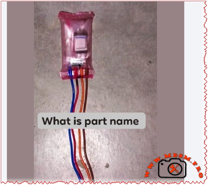
To successfully integrate this module into a refrigerator, one must identify the primary power feeds and load lines. Below is the standard industrial wiring configuration for these four-wire universal modules:
- Line 1 (Phase): Usually connected to the Brown or Black wire.
- Neutral (N): Connected to the Blue wire.
- Compressor Output (Terminal 4 equivalent): Connected to the Red wire.
- Defrost Heater Output (Terminal 2 equivalent): Connected to the Orange wire.
Engineer’s Note: Always verify the color coding with a multimeter before final soldering, as some manufacturers may swap the Orange and Red functions depending on the production batch.
Installation Strategy and Field Advice
When performing a “board bypass,” the objective is to restore the basic cooling logic: Compressor Run -> Accumulated Time -> Defrost Cycle -> Repeat.
- Thermal Protection: Ensure the defrost heater circuit remains in series with the original Bimetal Thermostat and Thermal Fuse. Never bypass safety components.
- Placement: Although encapsulated, avoid placing the module in areas prone to direct moisture or heavy vibration from the compressor.
- Connection Integrity: Use high-quality crimp connectors or solder with heat-shrink tubing to prevent oxidation in high-humidity environments.
Benefits of Using the Universal Electronic Module
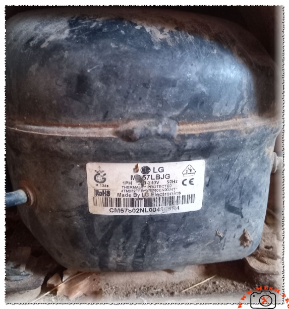
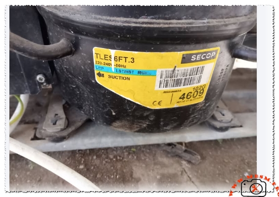
- Versatility: Compatible with almost all non-inverter brands including LG, Samsung, Whirlpool, and Daewoo.
- Durability: The solid-state design handles voltage fluctuations better than traditional mechanical motors.
- Compact Design: Its slim profile allows it to be tucked away inside the compressor compartment or the rear wiring panel.
Focus Keyphrase: Mbsmpro.com Universal Electronic Defrost Timer Module Wiring Schematic and Refrigerator Repair Guide for Technicians
SEO Title: Mbsmpro.com | Universal Electronic Defrost Timer | Wiring & Specs
Meta Description: Master the installation of the Universal Electronic Defrost Timer Module. Includes wiring schematics, technical specs, and professional HVAC repair advice.
Slug: universal-electronic-defrost-timer-wiring-schematic-mbsmpro
Tags: Mbsmgroup, Mbsm.pro, mbsmpro.com, mbsm, Refrigerator Repair, Defrost Timer, HVAC Engineering, Solid State Control, Cooling System Modification, Compressor Wiring
Excerpt: The Universal Electronic Defrost Timer Module is a critical component for modernizing refrigerator repairs. Designed to replace failing mechanical timers and expensive control boards, this solid-state device offers unmatched reliability. Featuring a 220V input and 10A capacity, it ensures precise timing for compressor operation and defrost cycles in various domestic refrigeration brands.