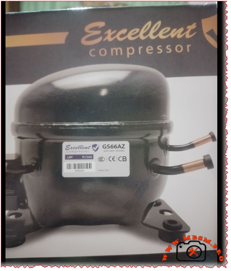
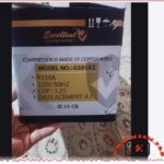
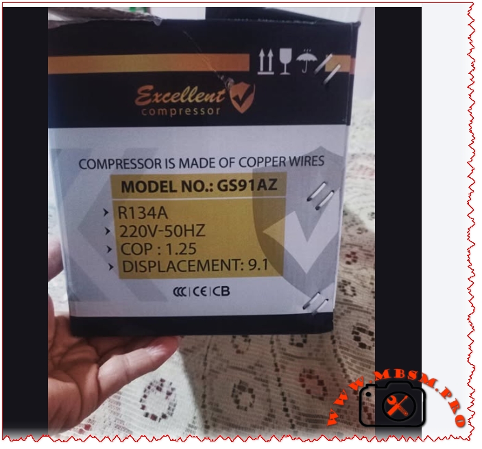
Excellent GS66AZ Compressor Technical Specifications, BIG 1/6 HP, 6.6 cm3
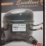
Excellent Compressor GS66AZ: A Comprehensive Technical Overview and Replacement Guide
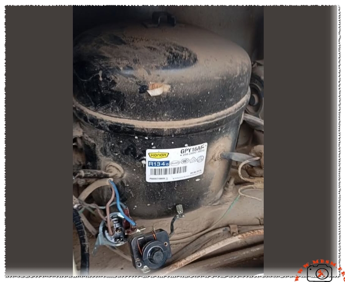
The GS66AZ is a robust and efficient hermetically sealed compressor designed for light commercial and high-demand domestic refrigeration applications. Engineered for reliability within specific thermal envelopes, this model represents a key component in sustaining consistent cooling performance. Its specifications indicate a design focused on energy efficiency and durable operation under continuous use conditions. This article provides a detailed technical breakdown, replacement guidelines, and practical insights for technicians and procurement specialists.
Complete Technical Specifications of the GS66AZ Compressor
| Parameter | Specification for GS66AZ |
|---|---|
| Model | GS66AZ |
| Utilisation | LBP (Low Back Pressure) |
| Domaine | Freezing / Low-Temperature Refrigeration |
| Oil Type and Quantity | Polyester (POE) Oil, specific quantity as per manufacturer datasheet (typically ~350ml) |
| Horsepower (HP) | Approximately 1/5 HP |
| Refrigerant Type | R134a |
| Power Supply | 220-240V ~ 50/60Hz, 1 Phase |
| Cooling Capacity BTU | To be confirmed from official performance curves (est. ~700-900 BTU/hr @ LBP conditions) |
| Motor Type | RSIR (Resistance Start Induction Run) |
| Displacement | Model-specific (refer to manufacturer data) |
| Winding Material | Copper |
| Pression Charge | Designed for low evaporating pressure applications |
| Capillary | System-dependent; must be matched to the condenser and evaporator for optimal performance. |
| Modele Frigo/Refrigerator Compatibility | Designed for low-temperature compartments in domestic refrigerators, standalone freezers, and commercial display freezers. |
| Temperature function | Optimal performance between -30°C to -10°C evaporating temperature range. |
| With fan or no | Typically used in fan-cooled condenser systems. |
| Commercial or no | Yes, Light Commercial / Heavy Domestic. |
| Amperage in function | Approx. 1.3 – 1.5 A at rated voltage and load. |
| LRA (Locked Rotor Amps) | To be confirmed from manufacturer label (typically 6-8 times running amps). |
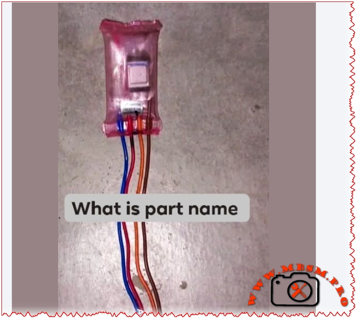
| Type of relay | PTC (Positive Temperature Coefficient) Start Relay. |
| Capacitor or no and value | No run capacitor (RSIR design). PTC relay provides starting assistance. |
| 5 Compressor replacements of same value in same gas (R134a) | GN66AZ, GE66AZ, GR66AZ, GJ66AZ, GP66AZ (Always verify model suffixes for exact electrical and mechanical compatibility). |
| 5 Compressor replacements of same value in other gas | Models designed for R600a (e.g., GN60AZ series) or R404A/R290 will have different electrical characteristics and are NOT direct drop-in replacements. System conversion required. |
Deep Dive: Application and Engineering Context
The LBP (Low Back Pressure) designation is crucial. It means this compressor is engineered to pump refrigerant where the evaporator (cooling compartment) operates at a very low pressure, corresponding to the -30°C to -10°C temperature range essential for freezing. This contrasts with MBP (Medium Back Pressure) compressors used for fresh food cooling (typically -5°C to +10°C) and HBP (High Back Pressure) units for air conditioning or beverage coolers.
Comparison with Other Compressor Types
| Feature | GS66AZ (LBP, R134a) | Typical MBP Compressor (e.g., for refrigerator section) | Miniature DC Compressor (e.g., for portable fridge) |
|---|---|---|---|
| Primary Use | Freezing / Deep Cooling | Fresh Food Preservation | Portable, 12/24V Applications |
| Efficiency at Low Temp | High (Optimized for this duty) | Poor (will overwork and fail prematurely) | Low to Moderate |
| Typical HP | 1/5 HP to 1/4 HP | 1/6 HP to 1/5 HP | < 1/10 HP |
| System Complexity | Standard AC single-phase | Standard AC single-phase | Requires DC power/control board |
| Durability | High (Commercial Duty) | Moderate (Domestic Duty) | Low to Moderate |
Key Benefits and Selection Advice
- Reliability: The RSIR motor with copper windings offers a simple, robust design well-suited for constant operation.
- Broad Voltage Compliance: The 220-240V 50/60Hz range makes it adaptable to power standards in many regions.
- Energy Consideration: While not an inverter model, its efficiency is optimized within its specified LBP operating window.
Critical Notices for Technicians:
- Oil Compatibility: POE oil is hygroscopic. Always keep the system open for a minimal time and use proper vacuum procedures to avoid moisture contamination and acid formation.
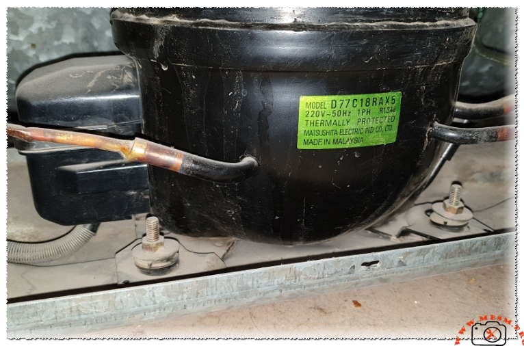
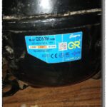
- Electrical Verification: Always check the actual nameplate on the unit. While the GS66AZ is common, suffixes may indicate different plug types or minor performance tweaks.
- Non-Direct Replacements: Swapping to a compressor using a different refrigerant (like R600a or R290) is not a simple plug-and-play. It requires changing the capillary tube, possibly the filter-drier, and ensuring correct oil charge, making it a job for qualified professionals.
- Overheating Protection: Ensure the original system’s overload protector and PTC relay are in good condition or replaced when installing a new compressor to prevent burnout.
Conclusion
The GS66AZ compressor is a workhorse for low-temperature refrigeration. Its value lies in its specific engineering for freezing applications, commercial-grade durability, and straightforward RSIR design. Successful implementation and replacement hinge on respecting its LBP designation, ensuring electrical compatibility, and following rigorous installation practices to ensure long system life and reliable performance.
Focus Keyphrase: GS66AZ compressor specifications R134a LBP freezing replacement commercial 220V
SEO Title: GS66AZ Compressor Specs & Replacement Guide | R134a LBP Freezing Unit | Mbsmpro.com
Meta Description: Complete technical analysis of the GS66AZ compressor. Covers specs, HP, LBP use, R134a gas, replacement models, and critical installation notices for freezer repair.
Slug: gs66az-compressor-specifications-replacement-guide
Tags: Mbsmgroup, Mbsm.pro, mbsmpro.com, mbsm, GS66AZ, Compressor Replacement, R134a Compressor, LBP Compressor, Freezer Compressor, Commercial Refrigeration, Hermetic Compressor, GN66AZ, GE66AZ, GR66AZ
Excerpt: The GS66AZ is a robust hermetically sealed compressor designed for light commercial and domestic freezing applications. This guide provides full technical specifications, including its LBP use for…