Before you touch anything, pull the power plug. It’s the easiest way to make sure nothing kicks on while your hands are inside the machine.
2. Relieve the Pressure
If this is a fridge or a water cooler, turn off the water line and try to get one last glass of water out. This drops the pressure so the filter doesn’t “pop” or spray you when you unscrew it. If it’s a compressor, bleed the air tank first.
3. The “Left-Loose, Right-Tight” Swap
Most 1/5 Hp systems use a simple twist-lock:
Remove: Twist the old filter a quarter-turn to the left (counter-clockwise) and pull it straight out.
Install: Pop the plastic caps off the new filter. Line up the little arrows or notches, push it in firm, and twist to the right until it clicks or stops.
4. The “Grey Water” Trick
If it’s a water filter, the first few cups will look cloudy or even blackish. That’s just harmless carbon dust. Run the water for about 3 to 5 minutes until it’s crystal clear.
1/5 HP Compressor oil change: How much and how to do it right
Category: Refrigeration
written by www.mbsmpro.com | April 13, 2026
Professional Commentary (The Spirit of the Craft)
“When we talk about a 1/5 HP compressor, we are essentially talking about the ‘heart’ of a domestic refrigerator or a small cooler. In this field, the fine details are what set a professional apart:
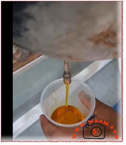
The Quantity: Typically, this size requires about 200 to 250 ml (depending on the model and manufacturer, such as Danfoss or Jiaxipera). The golden rule here is ‘precision by the milliliter.’ Excess oil can lead to ‘Oil Logging’ within the cooling circuit, while a deficit causes friction that eventually kills the compressor.
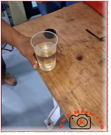
The Method: It’s not just about pouring oil; it’s a matter of integrity. You must ensure the old oil is completely drained while inspecting it for impurities. If the oil is black or has a burnt odor, it’s a clear diagnostic sign of the motor’s condition. As for recharging, it must be done via the service line using vacuum suction to ensure no moisture or air enters the system—moisture is the ultimate enemy of refrigeration oil.
The Oil Type: This is the trap! The oil must be selected based on the refrigerant type. For instance, R134a requires synthetic POE oil, whereas older models or those running on R600a may require different specifications.
A final word: Someone asking about the ‘quantity and method’ is a technician who respects their craft and aims for perfection, not just someone trying to ‘get the job done.'”
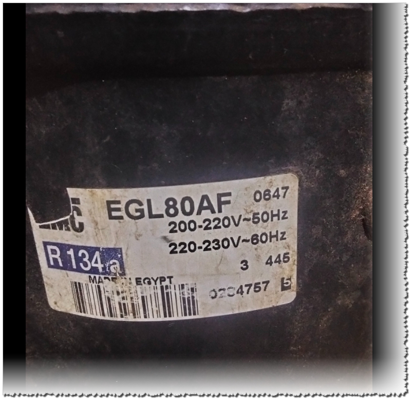
Can the GL80 compressor be installed in place of the GL90?
Category: Refrigeration
written by www.mbsmpro.com | April 13, 2026
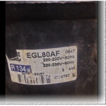
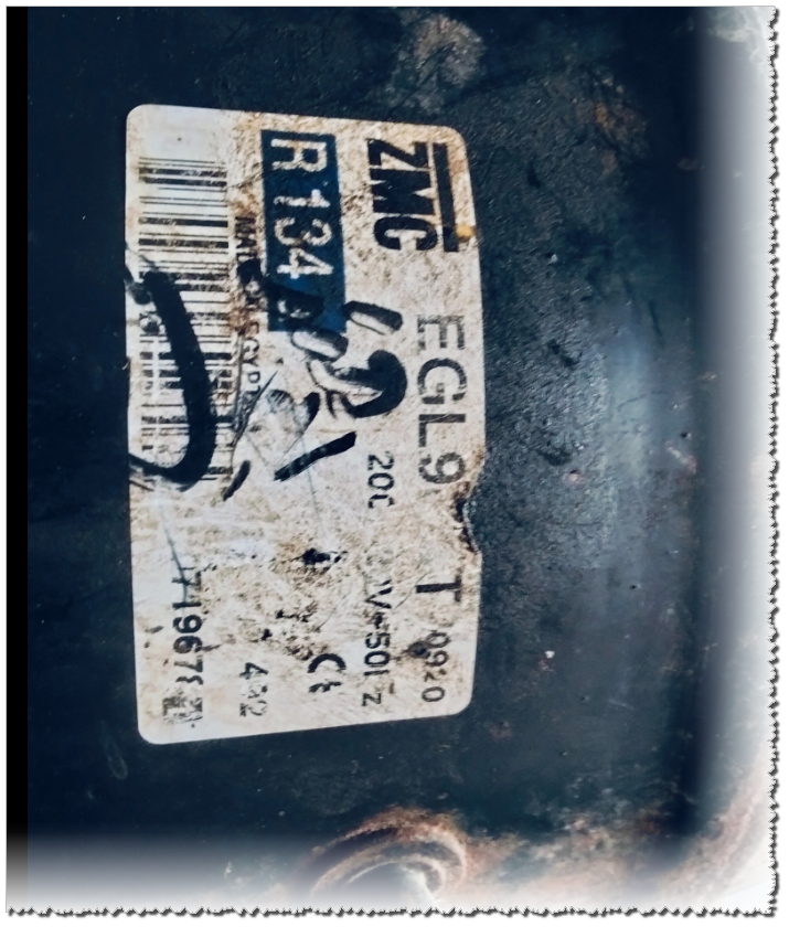
The main difference is the winding material: the GL80 uses aluminum coils, while the GL70 uses copper. Performance-wise, the GL80 is suitable for an upright deep freezer, whereas the GL70 is best for a 12ft double-door refrigerator “The technical difference between the two compressors, manufactured by ZEM or ACC, lies primarily in the horsepower (HP) and displacement volume:
GL80: Has a slightly lower capacity, rated at approximately 1/5 HP
GL90: Typically rated at 1/4 HP (or equivalent, depending on the specific model
Technical Conclusion: Compressor Interchanges
1. Replacing GL80 by GL90 yes 2. Replacing GL90 by GL80 non 3. Replacing GL80 by GL70 non 4. Replacing GL70 by GL80 yes
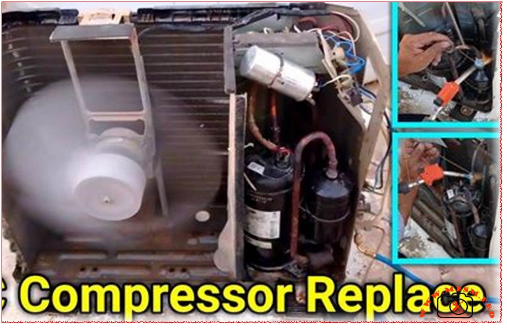
The process of replacing the air conditioner compressor is successful, and it is working as it was before ?
Category: Refrigeration
written by www.mbsmpro.com | April 13, 2026
“The process of replacing the air conditioner compressor is successful, and it is working as it was before.”
Alternatively, if you are asking whether the process is viable, it can be translated as: “Is replacing the air conditioner compressor effective, and will it work as well as it did before?”
Key Points regarding Compressor Replacement:
If you are considering this repair, here are a few things to keep in mind to ensure it works “as it was”:
Matching Specifications: The new compressor must have the exact same cooling capacity (BTU) and electrical specifications as the original.
System Flushing: It is vital to flush the refrigerant lines to remove any contaminants or burnt oil from the old compressor; otherwise, the new one may fail quickly.
Vacuuming: A deep vacuum must be pulled on the system to remove moisture before recharging with gas.
Cost-Benefit: Since the compressor is the “heart” of the AC, the repair can be expensive. If the unit is more than 10 years old, it is often more cost-effective to replace the entire unit.
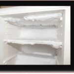
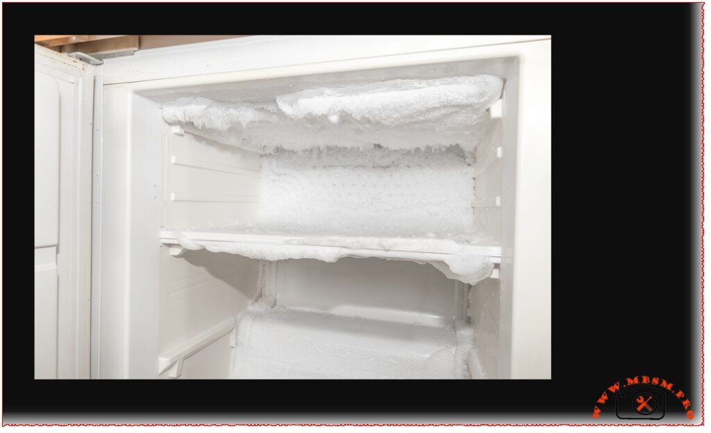
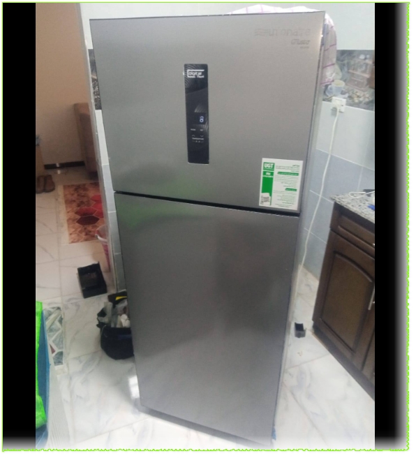
A problem with a Brand refrigerator: ice forms, it makes a noise, and it stops cooling
Category: Refrigeration
written by www.mbsmpro.com | April 13, 2026
The issues you are experiencing with your Brandt refrigerator (ice buildup, unusual noise, and poor cooling) indicate a failure in the No Frost defrost system. Since a specialist was unable to fix it, the fault may have been misdiagnosed.
Here is the translation of the causes and solutions provided:
Possible Causes and Solutions
1. Clogged Drain Line (Canal d’évacuation bouché)
The Cause: When ice melts during the defrost cycle, water must flow into the rear tray through a drain tube. If blocked, water freezes in the evaporator, obstructing airflow and cooling.
The Solution:
Unplug the refrigerator.
Locate the drain hole at the bottom of the freezer compartment.
Pour hot water into the hole to melt any ice blockage.
Use a thin wire or compressed air to ensure the tube is completely clear.
2. Faulty Ventilation Fan (Ventilateur bloqué ou HS)
The Cause: The fan distributes cold air. If it gets stuck due to ice buildup or suffers a mechanical failure, it will make noise and the fridge will stop cooling.
The Solution:
After defrosting the unit, turn it on and check if the fan spins when the door is closed.
If it doesn’t spin, try moving it manually. If it remains stuck, it likely needs replacement.
3. Defective Defrost Heater (Résistance de dégivrage)
The Cause: This heater melts ice periodically. If it fails, ice will accumulate continuously.
The Solution:
Test the heater using a multimeter (Ohms setting).
If the circuit is broken, the part must be replaced by a specialist.
4. Damaged Temperature Sensor or Thermostat (Sonde HS)
The Cause: If the sensor is faulty, the system won’t know when to trigger the defrost cycle, leading to excessive ice.
The Solution:
Replace the sensor (this is usually an inexpensive and straightforward fix).
What Should You Do Now?
Manual Defrost: Manually defrost the unit and follow the steps above.
Monitor: If the problem returns after a few days, the issue is likely electrical (the heater, sensor, or timer/control board).
Professional Check: For a permanent fix, ask a technician to specifically measure the resistance (heater) and the sensor rather than just performing a manual defrost.
[!CAUTION] Important Advice: Never scrape ice with sharp tools (like knives) to avoid puncturing the cooling coils, which would cause a permanent refrigerant leak.
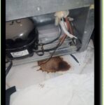
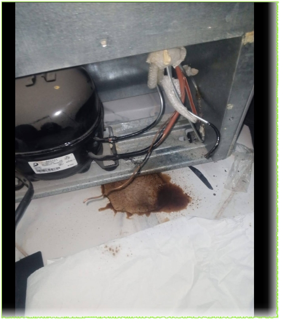
The refrigerator has a problem, it works for a minute and then shuts off
Category: Refrigeration
written by www.mbsmpro.com | April 13, 2026
Our technical investigation revealed a dual issue. The system was suffering from a restricted filter drier, causing a blockage that choked the cooling cycle. This strain had also compromised the motor’s starting components.
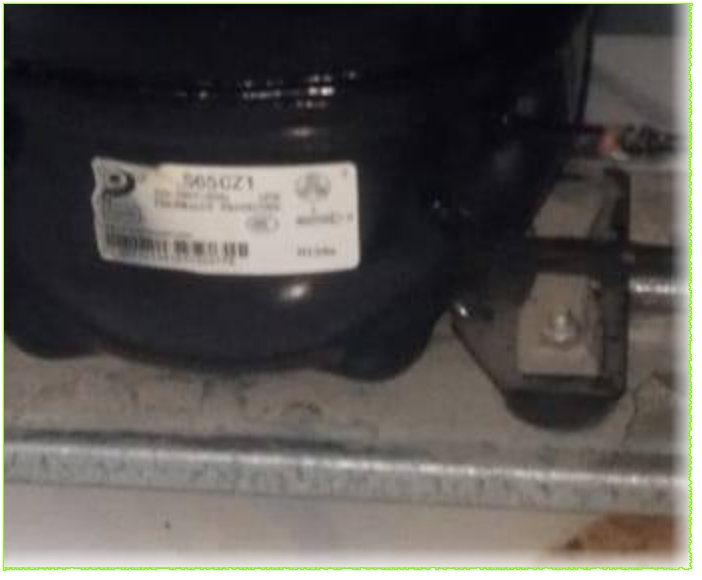
Technical Specifications
Feature
Specification
Model
S65CZ1
Brand
Panasonic
Refrigerant
R134a
Power Supply
220-240V / 50Hz
Cooling Capacity
Approximately 165W (at ASHRAE conditions)
Horsepower
1/5 HP
Displacement
6.5 cm3
Motor Type
RSIR (Resistive Start-Inductive Run)
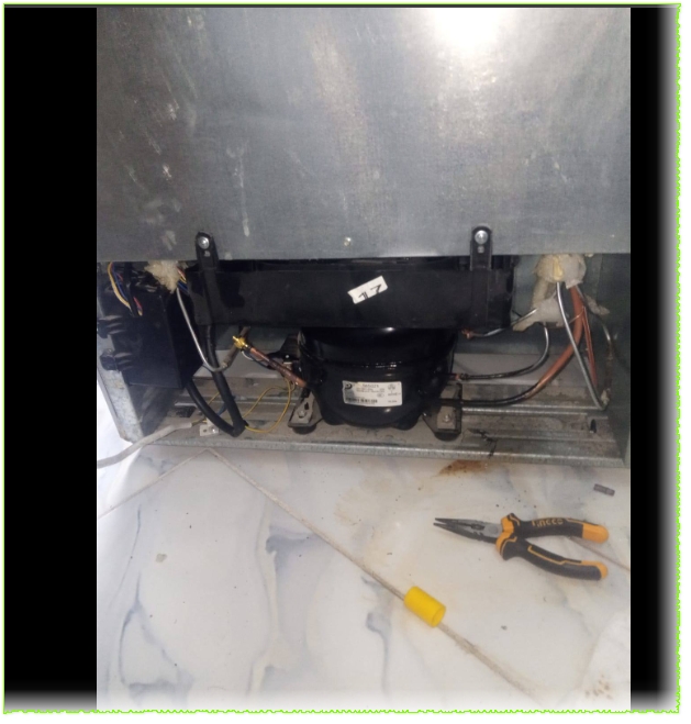
Our intervention included:
System Clearing: Replacing the clogged filter to allow the refrigerant to flow freely once again.
Electrical Upgrade: Installing a brand-new high-quality “Starting Kit” (Relay/Overload) to ensure the compressor starts smoothly every time.
The Mbsmpro Promise: We don’t just fix; we provide peace of mind. This repair is backed by a full 6-month warranty.
If you’ve ever opened the back panel of a commercial chest freezer or a light commercial display case and found a compact, brushless compressor with a controller module attached to it, there’s a good chance you were looking at a Danfoss Secop SLV15CNK. This variable-speed hermetic compressor is one of the most widely deployed LBP (Low Back Pressure) units in European and international commercial refrigeration — and for good reason.
Originally built under the Danfoss brand before the compressor division was spun off as Secop GmbH in 2010, the SLV15CNK has carved out a reliable reputation across commercial food retail, light industrial cooling, and even medical cold-chain applications. The unit pictured above — serial reference 561108N4, profile 104H — is the standard 220–240V, 50/60 Hz variant using R290 (propane) refrigerant, one of the most eco-friendly natural refrigerants available today.
Complete Technical Specifications Table
Parameter
Value
Model
SLV15CNK / SLV15CNK.2
Utilisation (MBP/HBP/LBP)
LBP only (Low Back Pressure)
Domain (Freezing/Cooling)
Deep Freezing — evap. temp. –40°C to –10°C
Cooling Wattage at –23°C
~446 W (nominal at standard LBP conditions)
Cubic Feet Cooled
~7–10 ft³ (small to medium chest freezer)
Litres Cooled
~200–280 litres
Kcal/h
~383 Kcal/h
TON
~0.127 TON of refrigeration
Oil Type & Quantity
Polyolester (POE) — 600 cm³
Horsepower (HP)
5/8 HP (~0.60 HP)
Refrigerant Type
R290 (Propane) — max charge 150 g
Power Supply
220–240V / 1Ph / 50–60 Hz (range: 180–254V)
Cooling Capacity BTU
~1521 BTU/h (LBP nominal)
Motor Type
Permanent Magnet (TRI — 3-phase inverter driven)
Displacement
15.28 cm³
Winding Material
Copper (3-phase windings, resistance ~7.7 Ω at 25°C)
Pression Charge
LBP / LST — max condensing temp 55°C (65°C short-term)
Capillary
Approx. 3m / Ø0.31 mm (application-dependent — verify with OEM data)
–40°C to –10°C evaporating; –35°C practical freezer operation
With Fan or Not
Yes — F2 fan cooling required (3.0 m/s airflow on compressor & controller)
Commercial or Domestic
Commercial (light commercial / food retail)
Amperage in Function
Max 4.6 A
LRA (Locked Rotor Amperage)
Electronic cut-off (no traditional LRA — inverter-controlled)
Type of Relay
No traditional relay — uses 105N46xx Series SLV Electronic Controller
Capacitor
No start/run capacitor — inverter-driven (variable speed 2000–4000 RPM)
Country of Origin & Export
Manufactured in Slovakia (Secop GmbH) — exported globally: EU, UK, Middle East, North Africa, Australia, Asia
What Makes This Compressor Special?
Variable Speed Technology
Most technicians encounter fixed-speed compressors day in and day out. The SLV15CNK breaks that mold entirely. It’s a variable speed drive (VSD) compressor, meaning its speed adapts continuously between 2000 and 4000 RPM based on thermal demand. The result is dramatically reduced energy consumption during low-load periods, less mechanical wear, and quieter operation — all things that matter enormously in a commercial food retail environment where a freezer runs 24/7, 365 days a year.
R290 — The Natural Refrigerant Advantage
R290 (propane) is not new, but its adoption in commercial compressors has accelerated rapidly in recent years thanks to its near-zero Global Warming Potential (GWP = 3) compared to the synthetic alternatives it replaces. The SLV15CNK uses a maximum charge of just 150 grams, which keeps it below the safety threshold for flammable refrigerant use in occupied spaces. That tiny charge, combined with propane’s excellent thermodynamic properties, means this compressor achieves high efficiency with a very light environmental footprint.
The Controller Dependency
One detail technicians absolutely must not overlook: this compressor will not function without its dedicated SLV electronic controller (105N46xx series). The label on the unit itself clearly states “Only with SLV controller.” This is not a traditional hermetic compressor you can simply wire up to a relay and a capacitor. The controller handles speed regulation, current protection, speed monitoring, and thermal protection all in one unit. Replacing or sourcing this controller is as important as finding the compressor itself.
Fan Cooling Is Mandatory
At all ambient conditions (32°C, 38°C, and 43°C), the datasheet specifies F2 cooling — meaning fan airflow of at least 3.0 m/s directly on both the compressor body and the electronic controller unit. Attempting to run this compressor without proper forced airflow will trigger thermal protection and lead to premature failure. This is a common oversight when installers replace the compressor without checking the cabinet’s fan arrangement.
Replacement Compressors — Same Gas (R290)
When the SLV15CNK reaches end of life or fails, the most straightforward replacements use the same R290 refrigerant. Here are five proven options:
#
Replacement Model
Brand
Notes
1
SLV15CNK.2 (104H8541)
Secop/Danfoss
Direct drop-in replacement — latest revision
2
SLV12CNK.2
Secop/Danfoss
Slightly lower displacement, same gas and controller family
3
SLV20CNK.2
Secop/Danfoss
Higher capacity option — same R290/controller platform
4
NLV14CNK
Secop/Danfoss
Fixed-speed variant on R290 LBP — requires relay/capacitor
5
SCM10CNX.2
Secop
R290, standard hermetic, LBP — no inverter controller needed
Replacement Compressors — Different Refrigerant
If R290 is not available in your region, or if you’re retro-fitting an older system, here are five equivalents using alternative refrigerants with comparable capacity:
#
Replacement Model
Brand
Refrigerant
Notes
1
SC15G
Secop/Danfoss
R404A / R507A
Classic LBP hermetic, no controller needed
2
NL11MF
Secop/Danfoss
R134a
LBP/MBP, standard hermetic
3
CAJ9513Z
Embraco
R404A
Direct LBP replacement at similar capacity
4
NEBL2134Z
Embraco
R600a
For domestic/light LBP applications
5
MTZ32-4VM
Danfoss
R452A/R404A
Slightly oversized but compatible for retrofits
⚠️ Important: Switching refrigerants requires changing the oil type, capillary tube, and verifying all safety certifications. Always consult the system manufacturer before cross-refrigerant replacement.
Typical Applications — Which Freezers Use This Compressor?
The SLV15CNK is the heart of many products you’ll recognize from the supermarket floor:
AHT Australian series chest freezers (confirmed via MBSM documentation)
Frozen food display cases at petrol stations and convenience stores
Ice cream chest cabinets in retail environments
The AHT connection is particularly well-documented — AHT is a major manufacturer of commercial freezers widely deployed across European and African retail chains, and the SLV15CNK is one of their standard compressor choices.
Installation & Service Notes
A few practical points every technician should keep in mind when working with this unit:
Controller wiring: Always refer to the 105N46xx wiring diagram. Polarity and signal connections matter — the controller is not interchangeable between all SLV variants.
Refrigerant handling: R290 is flammable (Class A3). Work in ventilated areas, avoid open flames, and use an R290-certified manifold gauge set. The 150g charge limit means leaks are rare but must be taken seriously.
Oil compatibility: POE oil is mandatory with R290 in this application. Do not substitute mineral oil or alkylbenzene — POE is pre-filled at the factory at 600 cm³.
Mounting vibration: The compressor ships with rubber mounting grommets. Always re-use or replace them — running on a hard mount increases noise and mechanical fatigue.
Capillary tube: The reference capillary for AHT applications is approximately 3m / 0.31mm diameter, but always measure and verify against the original system before cutting new tubing.
Why This Compressor Matters in 2025 and Beyond
The refrigeration industry is at a turning point. Synthetic refrigerants with high GWP are being phased out under F-Gas regulations in Europe and similar legislation worldwide. The SLV15CNK — running on propane with a permanent magnet variable-speed motor — represents exactly the direction the industry is heading: natural refrigerants, intelligent speed control, and reduced energy consumption without compromising reliability.
For service technicians, understanding this platform deeply isn’t just useful today — it’s preparation for the next decade of commercial refrigeration work.
Compressor, KCE444HAG, 3/8 HP, Copeland, R-134a, 1077 W, 2.2 A, 230V, HBP, CSCR, High Temp
Category: Refrigeration
written by www.mbsmpro.com | April 13, 2026
PHASE 1: SURGICAL IMAGE ANALYSIS
Feature
Visible Nameplate Data
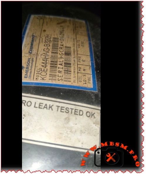
Brand
Emerson Climate Technologies / Copeland
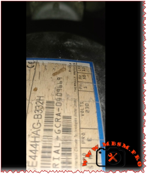
Model
KCE444HAG-B332H (Family: KCE444HAG)
Serial Number
GCRA-0909669
Voltage/Hz/Phase
1Ph 180-260 V AC / 230V, 50 Hz
Refrigerant
R-134a
LRA (Locked Rotor Amps)
13 A
Electrical Circuit
CSCR
Oil Type & Volume
10.5 oz POE (Polyolester)
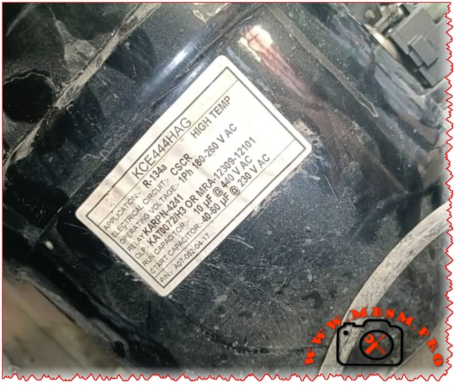
Application
High Temp (HBP)
Relay & OLP
Relay: KARPN-4241 / OLP: KAT0072/H3 OR MRA-12309-12101
Capacitors
Run: 10 µF @ 440 V AC / Start: 40-60 µF @ 230 V AC
Manufacturing Origin
Mfg. By Emerson Climate Technologies (India) Limited
PHASE 3: ARTICLE STRUCTURE
SEO Metadata
Focus Keyphrase: KCE444HAG Compressor
SEO Web Title: Mbsmpro.com, Compressor, KCE444HAG, 3/8 HP, Copeland, R-134a, 1077 W, 2.2 A, 230V, HBP, CSCR, High Temp
Meta Description: Technical specs for the Copeland KCE444HAG compressor. Includes LRA, displacement, electrical data, and equivalent drop-in cross-references for field techs.
Excerpt: Field data and technical breakdown of the Emerson Copeland KCE444HAG 3/8 HP commercial refrigeration compressor, including performance charts and direct replacement options.
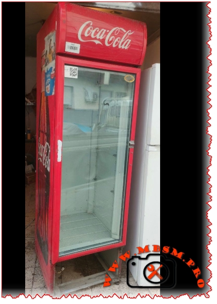
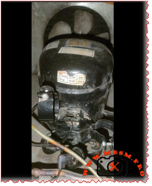
Field Introduction
Found this slugger in a glass-door Coca-Cola merchandiser or a heavy-duty sandwich prep table? You are looking at the Emerson Copeland KCE444HAG. This 3/8 HP unit is a cast-iron workhorse built to handle the constant door-opening abuse of commercial beverage coolers. When a shop owner relies on cold drinks to keep the lights on, this HBP (High Back Pressure) compressor does the heavy lifting. It runs smoothly on R-134a, but when it finally locks up or burns out a winding, you need the hard numbers to wire it back up or drop in a reliable match. Let’s break down the specs.
Full Nameplate Data Table
Here is exactly what is stamped on the steel:
Parameter
Specification
Manufacturer
Emerson Climate Technologies (Copeland)
Model
KCE444HAG-B332H
Serial
GCRA-0909669
Voltage
180-260 V AC (Rated 230V), 50 Hz
Phase
Single Phase (1Ph)
Locked Rotor Amps (LRA)
13 A
Refrigerant
R-134a
Application
High Temp
Motor Type
CSCR
Oil Charge
10.5 oz Polyolester (POE)
Country of Origin
India
Technical Specifications Table
Knowing what the compressor is doing on the inside dictates how you size the metering device and handle the system charge.
Specification
Value
Horsepower (HP)
3/8 HP
Displacement
12.05 cc
Cooling Capacity (HBP)
~3675 BTU/h / 1077 Watts
Application Type
HBP / CBP (High / Commercial Back Pressure)
Operating Voltage
230V
Motor Type
CSCR (Capacitor Start, Capacitor Run)
Max Continuous Current (MCC)
3.0 A
Rated Load Amps (RLA)
~2.2 A (at HBP standard conditions)
Electrical & Origin Details
Wiring up a CSCR motor means you are dealing with potential relays and dual capacitors. Don’t mix up your start and run values, or you will bake the new start winding before lunch.
Motor Circuit: CSCR (Capacitor Start, Capacitor Run) for high starting torque.
Start Capacitor:40-60 µF @ 230 V AC (Gets the heavy rotor moving against high head pressure).
Run Capacitor:10 µF @ 440 V AC (Keeps the power factor tight and the motor running cool).
Relay Model: KARPN-4241 (Potential Relay).
Overload Protector (OLP): KAT0072/H3 or MRA-12309-12101.
Here is how the KCE444HAG pulls down at varying evaporator temperatures (assuming a standard 130°F / 54.4°C condensing temp):
Evaporating Temp (°F / °C)
Cooling Capacity (BTU/h)
Power Input (Watts)
Amp Draw
45°F / 7.2°C (HBP)
3675
475
2.2
20°F / -6.7°C (CBP)
1880
339
1.64
0°F / -17.8°C
1190
268
1.33
Drop-in Replacements
If you can’t source a fresh Copeland KCE444HAG from the supply house, these 3/8 HP, ~12cc, R-134a HBP models will bolt right in and keep the cabinet at temp:
Embraco: NEK6210Z
Secop / Danfoss: SC12G
Jiaxipera: NT1112Y
GMCC: FL2088-SA
Cubigel / Huayi: GP12TB
Compressor, KCE444HAG, 3/8 HP, Copeland, R-134a, 1077 W, 2.2 A, 230V, HBP, CSCR, High Temp mbsmproCompressor, KCE444HAG, 3/8 HP, Copeland, R-134a, 1077 W, 2.2 A, 230V, HBP, CSCR, High Temp mbsmproCompressor, KCE444HAG, 3/8 HP, Copeland, R-134a, 1077 W, 2.2 A, 230V, HBP, CSCR, High Temp mbsmproCompressor, KCE444HAG, 3/8 HP, Copeland, R-134a, 1077 W, 2.2 A, 230V, HBP, CSCR, High Temp mbsmproCompressor, KCE444HAG, 3/8 HP, Copeland, R-134a, 1077 W, 2.2 A, 230V, HBP, CSCR, High Temp mbsmpro
Compressor, EMI 62UHR, 1/5 HP, Embraco, R134a, 140 W, 2.0 A, 127V, MBP, RSIR, Medium Back Pressure
Category: Refrigeration
written by www.mbsmpro.com | April 13, 2026
Focus Keyphrase: Embraco EMI 62UHR Compressor
SEO Web Title: Mbsmpro.com, Compressor, EMI 62UHR, 1/5 HP, Embraco, R134a, 140 W, 2.0 A, 127V, MBP, RSIR, Medium Back Pressure
Meta Description: Full technical specs for the Embraco EMI 62UHR compressor. Includes 127V 60Hz data, LRA, displacement, and compatible replacement models for Consul refrigerators.
Excerpt: Technical breakdown of the Embraco EMI 62UHR (1/5 HP) used in Consul CRD34BBANA refrigerators. Specs cover R134a usage, 127V/60Hz electricals, and cross-reference units.
Field Introduction
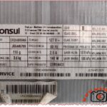
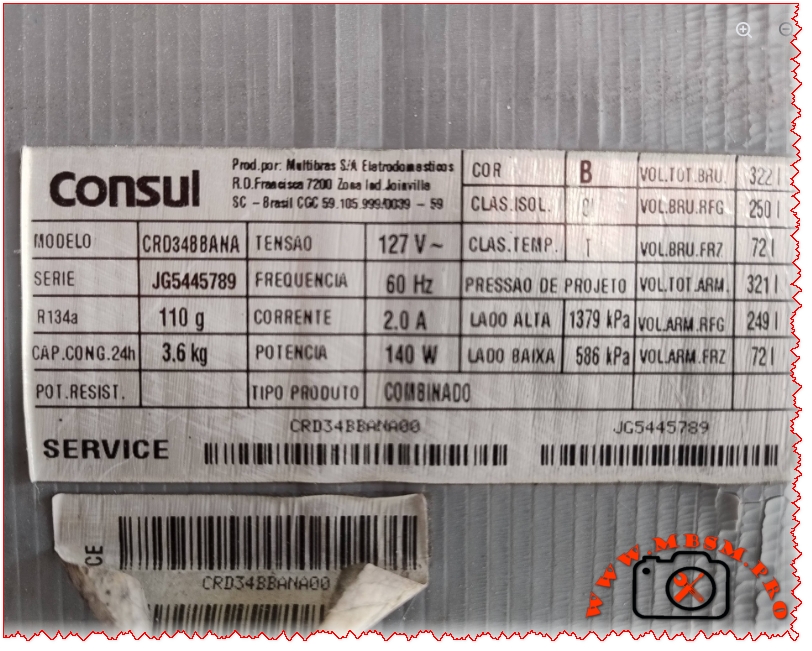
You’ll usually run into this Embraco EMI 62UHR tucked into the back of a Consul or Brastemp domestic refrigerator—specifically the CRD34B series popular in the Latin American market. It’s a workhorse for mid-sized “combinado” units (fridge/freezer combos). This specific unit is pulled from a system running on 127V at 60Hz, common in Brazil and parts of North America. If you see that rust on the shell in the photo, check the base plate and vibration isolators; these units vibrate a fair bit when the rubber gets hard, which can lead to hairline fractures in the discharge line.
Full Nameplate Data Table
Detail
Specification
Brand
Embraco
Model
EMI 62UHR
Serial Number
513307032
Voltage / Hz / Phase
115-127 V / 60 Hz / 1 Phase
Refrigerant
R134a
Current (RLA)
2.0 A
Power (Input)
140 W
Manufacturing Origin
Brazil (Multibras S.A.)
Appliance Model
Consul CRD34BBANA
Charge Amount
110 g (from appliance label)
Technical Specifications Table
Property
Value
Application
MBP (Medium Back Pressure)
Horsepower (HP)
1/5 HP
Cooling Capacity
~630 BTU/h (approx. 185 W)
Displacement
5.20 cc
Motor Type
RSIR (Resistance Start – Inductive Run)
Evaporating Temp Range
-10°C to +10°C (14°F to 50°F)
Expansion Device
Capillary Tube
Electrical & Origin Details
Motor Protector: Internal/External overload protector (T0490/G6).
Relay Type: PTC (Positive Temperature Coefficient).
Start Capacitor: Not required for RSIR (Standard configuration).
Manufacturing Country: Brazil.
Appliance Data: This unit is paired with the CRD34B Consul refrigerator, which features a total volume of 322L and a freezing capacity of 3.6kg every 24 hours.
Efficiency Metrics Table
Evaporating Temp (°C)
Cooling Capacity (W)
Power Consumption (W)
Efficiency (W/W)
-10
185
140
1.32
-5
225
152
1.48
0
275
165
1.67
+5
330
180
1.83
Drop-in Replacements
If you can’t find the exact EMI 62UHR, these units will bolt up and handle the load, provided you match the 127V/60Hz requirement:
Embraco: FF7.5HBK (Heavy-duty alternative)
Embraco: EMT6170Z (Modern high-efficiency swap)
Secop / Danfoss: TLES5.7FT.3
Tecumseh: THB1355YXA
Jiaxipera: GPY12AF
GMCC: SZ59C1H
Compressor, EMI 62UHR, 1/5 HP, Embraco, R134a, 140 W, 2.0 A, 127V, MBP, RSIR, Medium Back Pressure mbsmproCompressor, EMI 62UHR, 1/5 HP, Embraco, R134a, 140 W, 2.0 A, 127V, MBP, RSIR, Medium Back Pressure mbsmpro
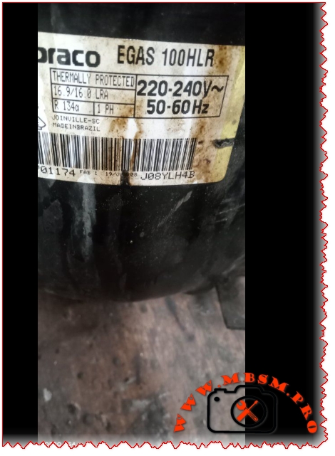
SEO Title: Embraco EGAS 100HLR Guide: Technical Specs & Field Replacements
Meta Description: Get the breakdown on the Embraco EGAS 100HLR. We cover LRA, R134a specs, displacement, and the best drop-in replacements for this common LBP workhorse.
Excerpt: The Embraco EGAS 100HLR is a staple in domestic refrigeration. This guide provides the raw technical data and equivalent models for fast field swaps.
Field Introduction
You’ll run into the Embraco EGAS 100HLR mostly in standard household refrigerators and large upright freezers. It’s a reliable Low Back Pressure (LBP) unit built for R134a. When these fail, it’s usually a hard start issue or a grounded winding after years of heat cycles. It’s a straightforward swap, but you need to match the displacement and LRA to keep the system balanced.
Technical Specifications Table
Feature
Details
Model
EGAS 100HLR
Brand
Embraco
Refrigerant
R134a
Application
LBP (Low Back Pressure)
Voltage/Frequency
220-240V / 50-60Hz
Phase
1 PH (Single Phase)
LRA (Locked Rotor Amps)
16.9 A (at 60Hz) / 16.0 A (at 50Hz)
Horsepower (HP)
~1/3 HP
Displacement
7.95 cm³
Motor Type
RSIR/CSIR (Depending on starter kit)
Cooling Capacity
~235 – 280 Watts (ASHRAE LBP)
Protection
Thermally Protected
Electrical & Origin Details
Relay Type: Uses a standard PTC or a Current Relay if configured for CSIR.
Capacitor Needs: Usually runs fine without a run capacitor (RSIR), but a start capacitor (approx. 60-80 µF) is often added for high-torque starts.
Manufacturing Origin: Joinville, Brazil (as seen on the nameplate).
Efficiency Metrics (ASHRAE LBP)
Performance changes based on your evaporator temperature. Here’s what to expect:
Evaporating Temp (°C)
Cooling Capacity (Watts)
Power Consumption (Watts)
COP (W/W)
-35
130
145
0.90
-30
185
170
1.09
-25
240
195
1.23
-23.3
265
205
1.29
-20
310
225
1.38
-15
390
255
1.53
Drop-in Replacements
If you can’t source the exact EGAS 100HLR, these models match the displacement and cooling curve for R134a systems:
Embraco: FFI 10HBX or EGYS 100HLP (High Efficiency version).
Secop/Danfoss: TLES10KK.3 or NLE10KK (Ensure R134a compatibility).
Jiaxipera: N1114GZ.
GMCC: SZ90E1H.
Huayi: HYE96YG.
Tecumseh: THG1374YS.
Field Note: Always replace the filter drier and pull a deep vacuum to 500 microns before charging R134a. This model uses POE oil; don’t leave the system open to the atmosphere for longer than necessary.