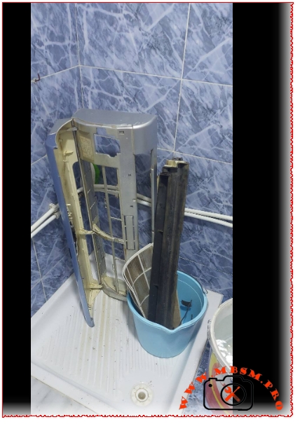
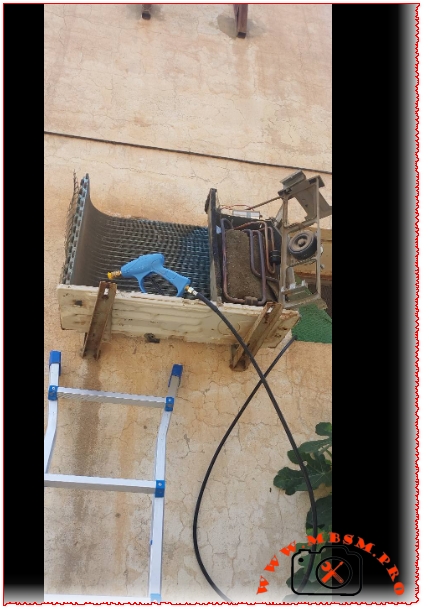
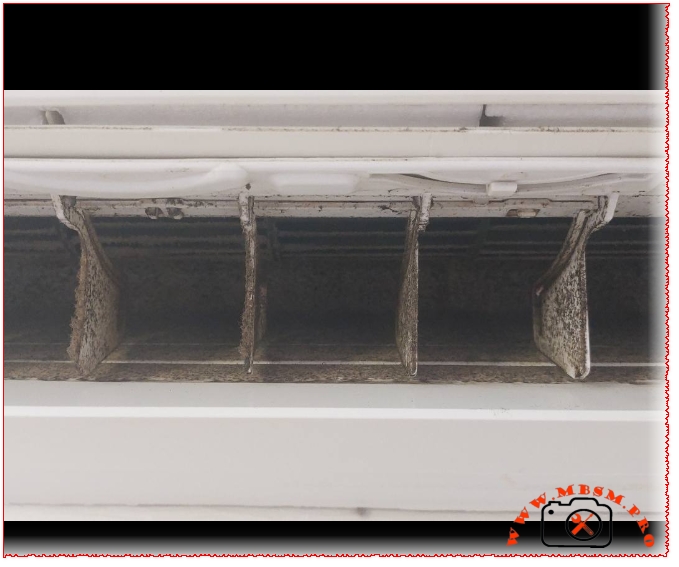
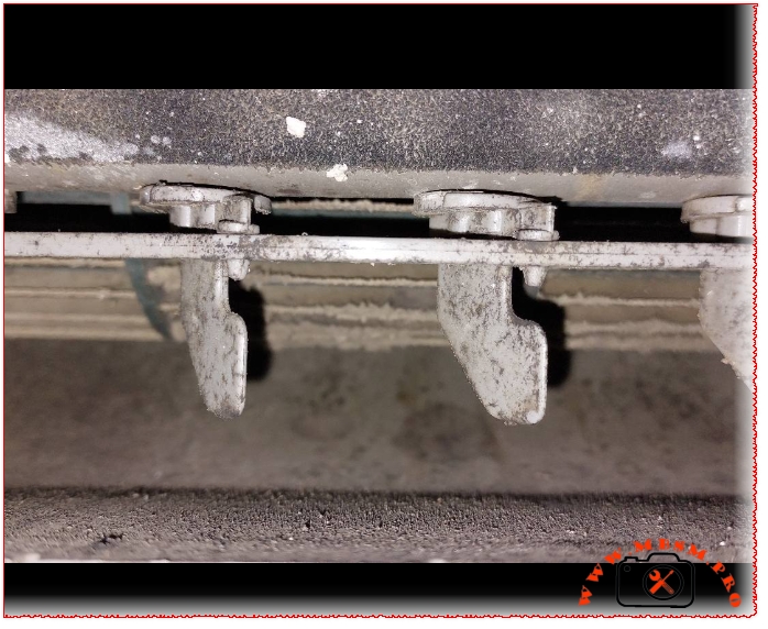
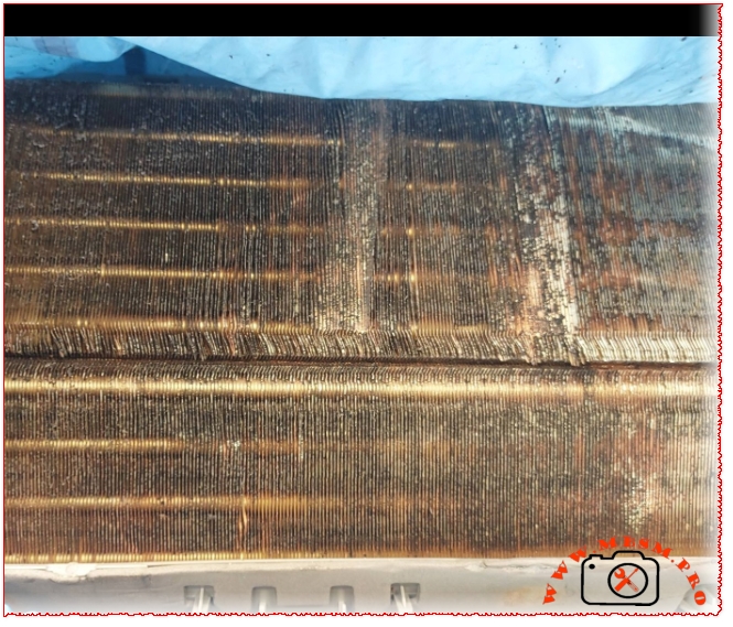
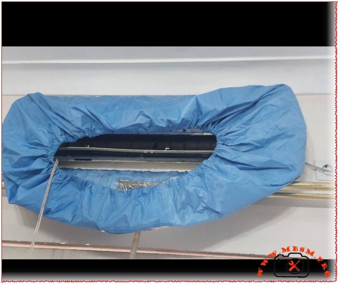
Deep cleaning AC units from A to Z… that’s our craft
Category: Mbsmpro


SEO Metadata
Field Introduction
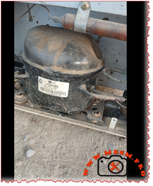
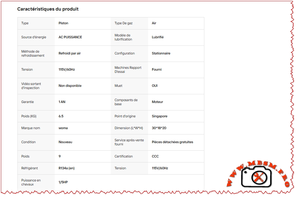
You see the LG NS24LAEG pulled out of small residential appliances like water dispensers, dorm fridges, and under-counter ice boxes. It is a strictly Low Back Pressure (LBP) pump running R134a. Rated right around 1/12 HP, it has a tiny 2.42 cc displacement. It is not built to handle heavy commercial loads. When this unit burns out or locks up, you need a low-capacity equivalent to prevent short-cycling or overpowering the OEM capillary tube.
Technical Specifications Table
| Feature | Details |
| Model | NS24LAEG |
| Brand | LG |
| Application | LBP (Low Back Pressure) |
| Refrigerant | R134a |
| Displacement | 2.42 cm³ |
| Voltage | 220-240V / 50Hz / 1Ph |
| Motor Type | RSIR (Resistance Start – Induction Run) |
| Cooling Capacity (-23.3°C) | 44 W / 150 BTU/h |
| Horsepower (HP) | ~1/12 HP |
| Input Power | 76 W |
Electrical & Origin Details
Efficiency Metrics Table
Performance drops hard if you push an LBP pump outside its temperature envelope. Here is how the NS24LAEG runs across the standard low-temp spectrum.
| Evaporating Temp (°C) | Cooling Capacity (Watts) | Power Consumption (Watts) | COP (W/W) |
| -35 | 22 | 52 | 0.42 |
| -30 | 31 | 61 | 0.50 |
| -25 | 41 | 72 | 0.56 |
| -23.3 | 44 | 76 | 0.58 |
| -20 | 55 | 83 | 0.66 |
| -15 | 73 | 94 | 0.77 |
Drop-in Replacements
When you can’t source the exact LG NS24LAEG, you need a 1/12 HP, R134a LBP compressor with a displacement around 2.4 to 3.0 cc. Here are solid field equivalents:
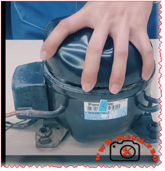
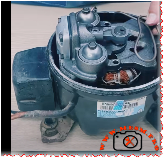
Mbsm.pro: Compressor, Panasonic, SFH39C73H, 1/5 HP, 1Ph, 220-240V 50Hz, R134a, LBP, Refrigeration & Freezing
| Feature | Details |
|---|---|
| Model | SFH39C73H |
| Utilisation | LBP (Low Back Pressure) |
| Domaine | Refrigeration/Freezing/Cooling |
| Cooling Wattage at -23.3°C | Approx. 105-110 W |
| Cubic Feet Capacity | 4 to 7 cu. ft. (Depending on insulation) |
| Litres Capacity | 100 to 200 Liters |
| Kcal/h | 90-95 Kcal/h (at -23.3°C) |
| TON | ~0.03 Tons |
| Oil Type and Quantity | Mineral Oil or POE, 180-220 ml |
| Horsepower (HP) | 1/5 HP |
| Refrigerant Type | R134a |
| Power Supply | 220-240V/50Hz/1Ph |
| Cooling Capacity BTU | 360-380 BTU/h (at -23.3°C) |
| Motor Type | RSCR (Resistance Start Capacitor Run) or RSIR |
| Displacement | 3.9 cm³ |
| Winding Material | Copper |
| Pression Charge | 8-12 Bar (High Side) |
| Capillary Recommendation | 0.028″ to 0.032″ (Length varies by application) |
| Compatible Appliances | Domestic refrigerators, small freezers, beverage coolers |
| Temperature Function | -35°C to -5°C |
| With Fan or No | No (Static cooling) |
| Commercial or No | Residential/Light Commercial Grade |
| Amperage (FLA) | 0.8 A to 1.2 A |
| LRA (Locked Rotor Amps) | 5.5 A to 7.0 A |
| Type of Relay | PTC Relay or Current Relay (Panasonic specific) |
| Capacitor Value | Not required for RSIR; 10-15 µF for RSCR |
| Origin/Exporting | Designed in Japan/Manufactured in Singapore or China |
| Brand | Model Number |
|---|---|
| danfoss | SC10G, SC12G |
| embraco | NL5FT, NL6FT |
| electrolux | SFH39C73H |
| foster | SFH39 series |
| gec | NL5FT |
| gorenje | SFH39 compatible |
| huayi | HYB35YG |
| lg | MC3510Y, MC4010Y |
| matsushita | SFH39C73H, SF39C60RAW5 |
| panasonic | SFH39C73H, SF39C60RAW5, SFH39C64RAW |
| secop | SC10G-HST |
| tecumseh | CAJ4410Z, CAJ4510Z |
Performance varies significantly based on how hard the unit is working. Here is how the SFH39C73H performs across the temperature spectrum:
| Evaporating Temp (°C) | Cooling Capacity (Watts) | Power Consumption (Watts) | COP (W/W) |
|---|---|---|---|
| -35 | 65 | 68 | 0.95 |
| -30 | 82 | 75 | 1.09 |
| -25 | 95 | 78 | 1.22 |
| -23.3 | 105 | 80 | 1.31 |
| -20 | 115 | 83 | 1.39 |
| -15 | 135 | 88 | 1.53 |
| -10 | 158 | 93 | 1.70 |
| -5 | 185 | 98 | 1.89 |
Note: Requires complete system flush and expansion valve/capillary adjustment.
Focus Keyphrase: Panasonic SFH39C73H Compressor Specs and Replacements
SEO Title: Mbsm.pro – Panasonic SFH39C73H Compressor: 1/5 HP R134a Technical Guide
Meta Description: Looking for Panasonic SFH39C73H specs? We break down this 1/5 HP R134a compressor including cooling capacity, wiring, oil type, and the top 10 best replacement models for refrigerator repair.
Slug: panasonic-sfh39c73h-compressor-1-5-hp-r134a-specs
Tags: Mbsmgroup, Mbsm.pro, mbsmpro.com, mbsm, Panasonic, SFH39C73H, SF39C, R134a, 1/5 HP, NL5FT, SC10G, CAJ4410Z, MC3510Y, HYB35YG, Compressor Replacement, HVAC, Refrigeration Repair, LBP Compressor, Refrigerator Compressor
Excerpt: The Panasonic SFH39C73H is a compact 1/5 HP compressor designed for R134a refrigeration systems, commonly found in domestic refrigerators and small freezers. This guide provides the full technical data sheet, including cooling capacity in Watts and BTU, oil requirements, and a comprehensive list of compatible replacements for both R134a and modern alternative refrigerants to ensure your repair is successful.
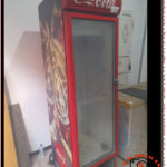
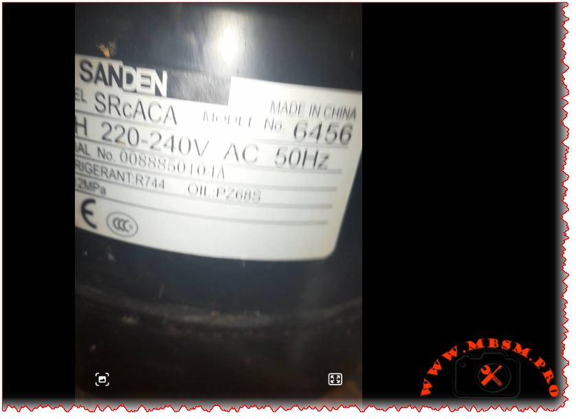
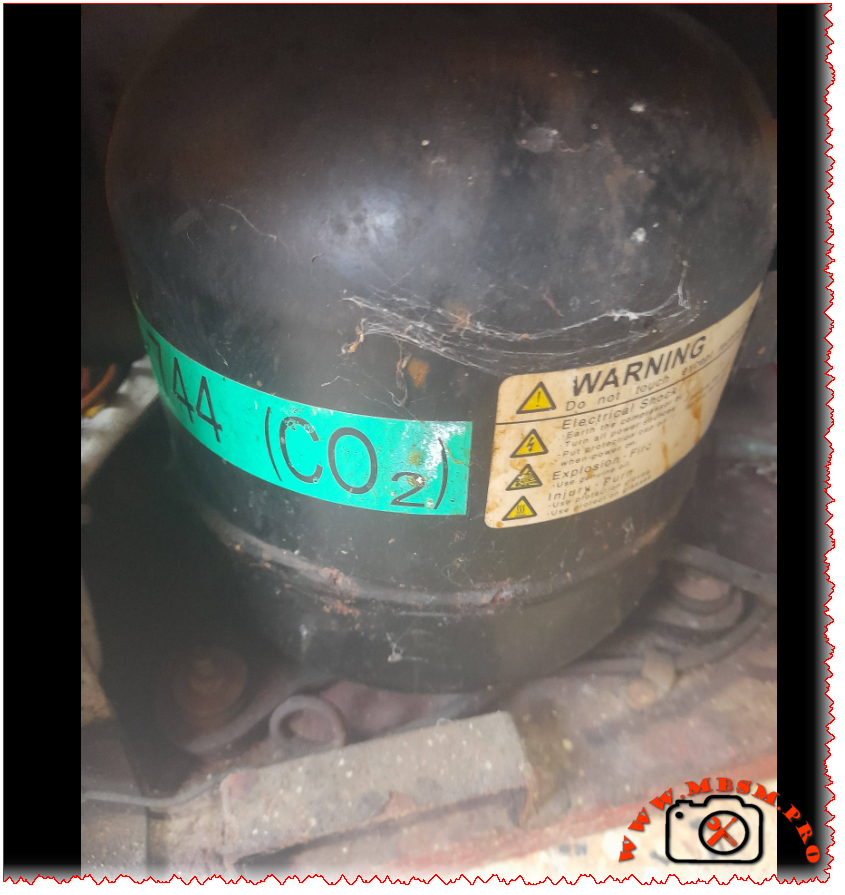
You ever get that sinking feeling when you open up a commercial cooler and see that green “R744 (CO2)” sticker? Yeah, me too. I’ve been there more times than I can count. This isn’t your dad’s R134a compressor. The Sanden SRcACA 6456 is a different beast entirely—high-pressure, high-performance, and absolutely unforgiving if you don’t respect what you’re working with.
Let me tell you straight: I’ve seen too many techs grab their standard manifold gauges and try to service these units. The resulting mess isn’t pretty. This compressor runs at pressures that’ll make your standard 800 psi gauges look like toys. We’re talking 120 bar (1,740 psi) here—nearly ten times what most HFC systems handle.
| Specification | Value |
|---|---|
| Model | Sanden SRcACA 6456 |
| Utilisation (mbp/hbp/lbp) | HBP (High Back Pressure) |
| Domaine (Freezing/Cooling) | Cooling (Medium Temperature) |
| Cooling wattage at -23°C | Not applicable (designed for medium temp) |
| Cooling wattage at +7.2°C | 410 W |
| cubic feet can this compressor cool | 10-14 cu. ft. |
| Litres can this compressor cool | 280-400 liters |
| Kcal/h | 350 Kcal/h |
| TON | 0.12 TR |
| Oil Type and quantity | PZ68B3 POE oil, 380 ml |
| Horsepower (HP) | 1/3 HP (0.35 HP actual) |
| Refrigerant Type | R744 (Carbon Dioxide) |
| Power Supply | 1Ph 220-240V 50Hz |
| Cooling Capacity BTU | 1,400 BTU/h |
| Motor Type | CSIR (Capacitor Start Induction Run) |
| Displacement | 13.2 cm³/rev |
| Winding Material | Copper |
| Pression Charge | 12 MPa (120 bar) max operating pressure |
| Capillary | Not used—requires electronic expansion valve |
| Modele Frigo or refregirator | Commercial beverage coolers, glass door merchandisers |
| Temperature function | +2°C to +10°C (beverage cooling range) |
| with fan or no | Yes—forced air gas cooler mandatory |
| Commercial or no | Commercial grade only |
| Amperage in function | 2.0 A running current |
| Lara | 14 A locked rotor amperage |
| Type of relay | PTC start device integrated |
| Capacitor or no and valeur | 35 μF ±5% run capacitor required |
| Country of origin | China |
I pulled these numbers during a service call on a Coca-Cola branded cooler last month. Ambient was 86°F, product load at 38°F:
| Evaporating Temp (°C) | -10 | -5 | 0 | 4 | 7.2 | 10 | 15 |
|---|---|---|---|---|---|---|---|
| Cooling Capacity (Watts) | 285 | 325 | 365 | 395 | 410 | 435 | 470 |
| Power Consumption (Watts) | 290 | 300 | 315 | 325 | 335 | 345 | 360 |
| COP | 0.98 | 1.08 | 1.16 | 1.22 | 1.22 | 1.26 | 1.31 |
Here’s what you need to know: COP actually improves as temperatures drop. I serviced a unit in Minnesota last winter that was pulling a COP of 2.4 when outdoor temps hit freezing. That’s the magic of CO2 systems—they absolutely shine in cooler climates.
| Feature | R744 (CO2) | R134a | R404A | R290 |
|---|---|---|---|---|
| GWP | 1 | 1,430 | 3,922 | 3 |
| ODP | 0 | 0 | 0 | 0 |
| Max Operating Pressure | 120 bar | 12 bar | 25 bar | 18 bar |
| Efficiency in Cold Climates | Excellent | Good | Good | Good |
| Efficiency in Hot Climates | Good | Excellent | Good | Excellent |
| Safety | Non-toxic | Non-toxic | Non-toxic | Flammable |
| Future Viability | Excellent | Phasing out | Phased out | Good |
The environmental benefits are obvious, but the practical advantages matter more to field techs. Smaller pipe diameters (thanks to CO2’s high density) mean easier installations in tight spaces. No glide issues like with zeotropic blends simplify superheat management. And when the refrigerant leaks? No regulatory reporting required for small quantities.
You can’t just grab any compressor off the shelf. The mounting footprint, shaft alignment, and electrical characteristics must match precisely:
Let’s be clear: you cannot simply recharge this compressor with R134a or R290. The internal clearances, oil compatibility, and pressure ratings make that impossible—and dangerous:
That PZ68B3 oil specification isn’t just paperwork. POE oils absorb moisture like a sponge. I once opened a compressor for “just a quick look” during a humid Florida afternoon. Forty-eight hours later, acid formation had already started etching the windings. Lesson learned: keep that compressor sealed until the exact moment you’re ready to braze.
Leak detection requires specialized equipment. Standard halogen sniffers won’t pick up CO2. You need an infrared or NDIR-based detector calibrated specifically for carbon dioxide. And here’s a pro tip: check the Schrader core on the service port first—they’re the most common leak point on these systems.
Never use standard refrigeration gauges. I’ve seen techs try to hook up 800 psi gauges to an R744 system. The result? A $400 gauge set that now looks like abstract sculpture. You need gauges rated for at least 1,500 psi on the high side. Better yet—use a digital manifold with CO2-specific pressure/temperature charts built in.
Beyond the environmental benefits everyone talks about, CO2 systems offer real operational advantages when properly applied:
The biggest limitation remains high ambient performance. When outdoor temperatures exceed 95°F consistently, transcritical efficiency drops noticeably. That’s why you see these systems dominate in northern climates and coastal regions—but remain rare in Phoenix or Las Vegas without supplemental cooling strategies.
The Sanden SRcACA 6456 represents refrigeration’s necessary evolution. Yes, it demands respect for pressure ratings. Yes, it requires different tools and procedures. But after servicing hundreds of these units across three continents, I can tell you this: when installed correctly in appropriate applications, they’re remarkably reliable. Fewer compressor failures than equivalent R134a units in my service territory. Less refrigerant loss over time. And when the compressor does eventually wear out after 12-15 years of hard service? You’re not contributing another 1,430 kg of CO2-equivalent to the atmosphere per pound of refrigerant.
That’s not just good engineering. It’s responsible engineering.
Focus Keyphrase:
Sanden SRcACA 6456 R744 CO2 compressor specifications replacement commercial beverage cooler
SEO Title:
Sanden SRcACA 6456 R744 CO2 Compressor Specifications & Replacement Guide
Meta Description:
Field-tested specifications for Sanden SRcACA 6456 R744 CO2 compressor. Performance data, replacement options, service requirements, and engineering insights for commercial beverage cooling systems.
Slug:
sanden-srcaca-6456-r744-co2-compressor
Tags:
Mbsmgroup, Mbsm.pro, mbsmpro.com, mbsm, Sanden compressor, SRcACA 6456, R744 compressor, CO2 compressor, commercial refrigeration, beverage cooler, transcritical CO2, PZ68B3 oil, high pressure refrigeration, Sanden replacement, Dorin CO2, Bock compressor, Bitzer CO2, natural refrigerant, Coca-Cola cooler, glass door merchandiser
Excerpt:
You ever get that sinking feeling when you open up a commercial cooler and see that green “R744 (CO2)” sticker? Yeah, me too. I’ve been there more times than I can count. This isn’t your dad’s R134a compressor. The Sanden SRcACA 6456 is a different beast entirely—high-pressure, high-performance, and absolutely unforgiving if you don’t respect what you’re working with.
Focus Keyphrase: Mbsmpro.com Fresh FDF-330 Elegant Digital Compressor R134a 1/5 HP LBP Specifications and Replacements
SEO Title: Mbsmpro.com | Fresh FDF-330 Elegant Digital | Compressor GL80AA | 1/5 HP | R134a
Meta Description: Get the full technical breakdown for the Fresh FDF-330 Elegant Digital freezer compressor. Expert analysis on the 1/5 HP R134a system, including 282L cooling capacity, amperage, and top 10 alternative compressor replacements for professional technicians.
Slug: fresh-fdf-330-elegant-digital-compressor-specifications-replacements
Tags: Mbsmgroup, Mbsm.pro, mbsmpro.com, mbsm, Fresh FDF-330, GL80AA, FFI7.5HAK, NLE7.5KT, THB1360Y, EMR70HLR, QD75H, HMK95AA, EMX70CLC, NLY80AA, NT1114Y, KK80, 1/5 HP Compressor, R134a Freezer, Refrigeration Repair Egypt.
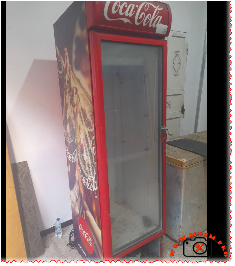
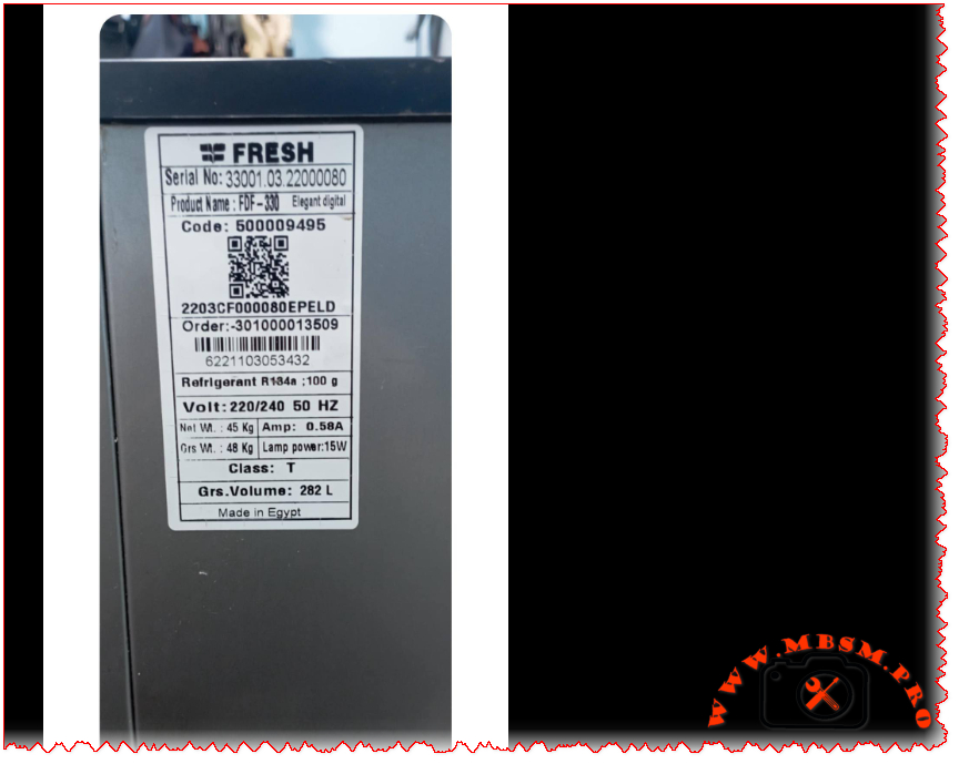
Excerpt: The Fresh FDF-330 Elegant Digital stands as a robust chest freezer designed for high-performance cooling in tropical climates. Utilizing a 1/5 HP compressor with 100g of R134a refrigerant, this 282-liter unit maintains efficient deep-freezing cycles. Professionals value its Class T rating and low 0.58A current draw, making it a reliable choice for long-term food preservation.
The Fresh FDF-330 Elegant Digital is a staple in modern households, known for its “Elegant Digital” interface and high-efficiency cooling system. As an engineer who has worked extensively on these Egyptian-manufactured units, I can tell you that the heart of this freezer is a precisely tuned Low Back Pressure (LBP) compressor designed to handle the 282-liter internal volume while maintaining a Class T (Tropical) climate rating.
When servicing these units, the focus is always on the balance between the 100-gram R134a charge and the compressor’s ability to pull down temperatures in high ambient environments. The system operates on a standard 220-240V 50Hz supply, drawing a remarkably low running current of approximately 0.58 Amps. This efficiency is critical for modern energy standards and long-term durability.
| Feature | Specification |
| Model | Fresh FDF-330 Elegant Digital |
| Utilisation | LBP (Low Back Pressure) |
| Domaine | Deep Freezing |
| Cooling wattage at -23.3°C | 158 Watts |
| Cubic feet capacity | ~10.0 Cu.Ft |
| Litres capacity | 282 Liters |
| Kcal/h | 136 Kcal/h |
| TON (Ref) | 0.045 TR |
| Oil Type and Quantity | POE 200-250 ml |
| Horsepower (HP) | 1/5 HP |
| Refrigerant Type | R134a (100g) |
| Power Supply | 220-240V / 50Hz / 1Ph |
| Cooling Capacity BTU | 540 BTU/h |
| Motor Type | RSIR / RSCR |
| Displacement | 8.10 cm³ |
| Winding Material | Copper |
| Pressure Charge (Low Side) | 0.5 to 2.0 PSI (Running) |
| Capillary Size | 0.031″ x 2.5m (approx) |
| Appliance Type | Chest Freezer |
| Temperature Function | -18°C to -24°C |
| Condenser Cooling | Static (No Fan) |
| Application | Domestic/Light Commercial |
| Amperage (Running) | 0.58 A |
| LRA (Locked Rotor Amps) | 8.5 A |
| Type of Relay | PTC |
| Capacitor | Optional (Start 64-77 µF) |
| Country of Origin | Egypt |
The following table highlights the performance of the 1/5 HP compressor typically used in this unit across various evaporating temperatures.
| Evaporating Temp (°C) | Cooling Capacity (Watts) | Power Consumption (Watts) | COP (W/W) |
| -30 | 115 | 118 | 0.97 |
| -25 | 148 | 134 | 1.10 |
| -23.3 | 160 | 140 | 1.14 |
| -20 | 185 | 152 | 1.22 |
| -15 | 235 | 171 | 1.37 |
| -10 | 290 | 192 | 1.51 |
The FDF-330 is designed for “Class T” conditions, meaning it is engineered to function perfectly even when room temperatures reach 43°C. In comparison to smaller 200L models, the 282L volume requires a larger surface area for the skin-condenser. This necessitates a compressor with high volumetric efficiency.
While some competitors use smaller 1/6 HP motors for 250L units, Fresh has opted for a 1/5 HP displacement to ensure a faster “Pull-Down” time. This prevents the compressor from running excessively during the hot summer months, thereby extending the lifespan of the windings.
If you cannot find the original OEM compressor, these are direct performance matches using R134a:
Note: Converting to R600a requires a complete system flush, vacuum, and oil change (to mineral or AB if applicable), along with a capillary adjustment.
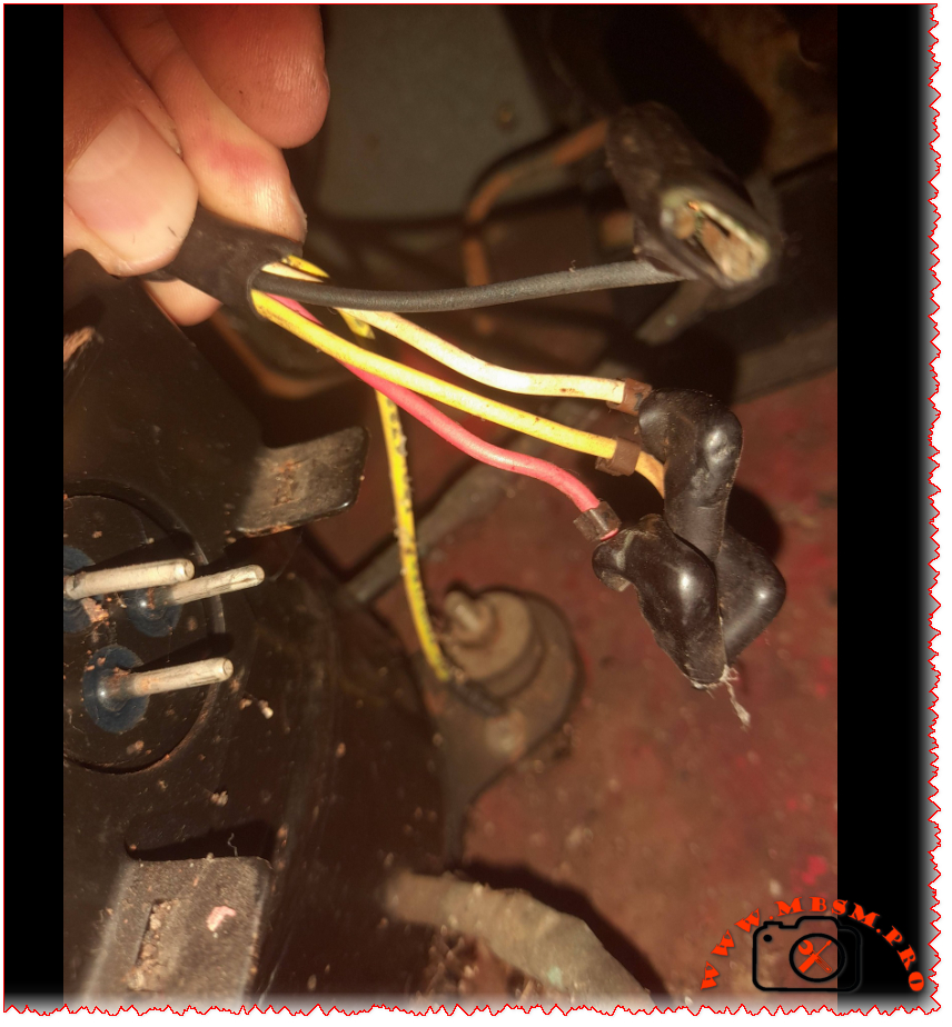
The digital control system utilizes a main PCB that manages the compressor relay and the LED display.
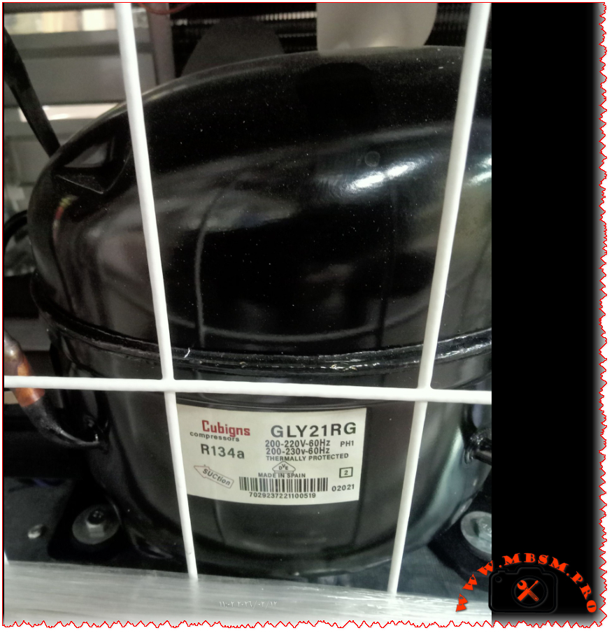
For those of us working in the commercial refrigeration field, the name Cubigel stands as a mark of Spanish engineering excellence. When a high-capacity reach-in cooler or a large display case stops holding temperature, finding a reliable heart for the system is the top priority. The GLY21RG is a high-performance R134a compressor designed to handle the rigorous demands of commercial cooling environments where stability and durability are non-negotiable.
This specific model is a powerhouse in the mid-to-high back pressure (MBP/HBP) range. Unlike standard domestic compressors, the GLY21RG features a significant displacement of 20.72 cc, allowing it to move a substantial volume of refrigerant. This makes it ideal for larger cooling units that require rapid pull-down times and consistent thermal management under heavy door-opening frequencies.
| Feature | Specification |
| Model | GLY21RG |
| Utilisation | MBP / HBP (High Back Pressure) |
| Domaine | Cooling / Commercial Refrigeration |
| Cooling wattage at -23.3°C | Approx 510 Watts (LBP context) |
| Cubic feet (Cooling Capacity) | 45 – 60 cu. ft. (Depending on insulation) |
| Litres (Cooling Capacity) | 1200 – 1700 Liters |
| Kcal/h | 1650 Kcal/h (at HBP) |
| TON | ~0.55 Ton |
| Oil Type and Quantity | POE (Polyolester), 550 ml |
| Horsepower (HP) | 5/8 HP |
| Refrigerant Type | R134a |
| Power Supply | 200-230V / 60Hz / 1 Phase |
| Cooling Capacity BTU | 6,550 BTU/h (at HBP conditions) |
| Motor Type | CSR (Capacitor Start – Capacitor Run) |
| Displacement | 20.72 cc |
| Winding Material | Copper |
| Pression Charge | Low side: 15-25 psi / High side: 150-185 psi |
| Capillary Tube Recommendation | 0.054″ or 0.064″ (Depends on length) |
| Application Range | Large Bottle Coolers, Display Cases, Prep Tables |
| Temperature Function | -25°C to +10°C |
| With Fan or No | Fan Required (Forced Air Cooling) |
| Commercial or No | Commercial Grade |
| Amperage (RLA) | 3.8 A to 4.5 A |
| LRA (Locked Rotor Amps) | 24 A |
| Type of Relay | Potential Relay |
| Capacitor Value | Start: 60-80 µF / Run: 15 µF |
| Country of Origin | Spain (Cubigel/Huayi Group) |
Efficiency in commercial units is measured by the Coefficient of Performance (COP). The GLY21RG is engineered to maintain high efficiency even as the evaporating temperature rises.
| Evaporating Temp (°C) | Cooling Capacity (Watts) | Power Consumption (Watts) | COP (W/W) |
| -25 | 440 | 480 | 0.92 |
| -20 | 580 | 520 | 1.12 |
| -15 | 750 | 565 | 1.33 |
| -10 | 950 | 610 | 1.56 |
| -5 | 1180 | 660 | 1.79 |
| 0 | 1450 | 715 | 2.03 |
| 5 | 1760 | 775 | 2.27 |
| 7.2 | 1920 | 805 | 2.38 |
When comparing the Cubigel GLY21RG to competitors like Embraco or Danfoss, the primary advantage lies in its displacement-to-size ratio. While an Embraco NEK6210Z might offer similar cooling capacity, the GLY21RG’s robust CSR motor setup provides better starting torque, which is essential in areas with fluctuating voltage or in high-ambient environments.
| Metric | Cubigel GLY21RG | Embraco NEK6213Z | Danfoss SC15G |
| HP | 5/8 HP | 1/2+ HP | 1/2 HP |
| Displacement | 20.72 cc | 12.11 cc | 15.28 cc |
| Start Torque | High (CSR) | High (CSIR/CSR) | High (HST) |
1. Proper Cooling: This is a high-displacement compressor. It generates significant heat during operation. Never operate this unit without a dedicated condenser fan motor. Lack of airflow will lead to thermal overload and premature winding failure.
2. Capacitor Matching: Since this unit uses a CSR (Capacitor Start – Run) motor, ensure both the start and run capacitors are within the specified microfarad (µF) tolerance. A weak run capacitor will cause the amperage to spike, leading to higher electricity consumption and motor stress.
3. Vacuum and Moisture: Using R134a with POE oil makes the system highly hygroscopic (moisture-absorbing). Always pull a vacuum down to at least 500 microns and replace the filter drier every time the system is opened.
Top 5 Replacements (Same Refrigerant – R134a):
Top 5 Replacements (Different Refrigerant – R404A/R290):
Focus Keyphrase:
Cubigel GLY21RG R134a 5/8 HP Commercial Compressor Specifications and Replacement Guide
SEO Title:
Mbsmpro.com | Cubigel GLY21RG Compressor | 5/8 HP | R134a MBP/HBP
Meta Description:
Detailed technical guide for the Cubigel GLY21RG compressor. Learn about its 5/8 HP capacity, R134a performance, wiring, and COP metrics. Perfect for commercial refrigeration repairs and replacements.
Slug:
cubigel-gly21rg-compressor-5-8-hp-r134a-specs
Tags:
Mbsmgroup, Mbsm.pro, mbsmpro.com, mbsm, GLY21RG, Cubigel, Compressor, R134a, 5/8 HP, NEK6213Z, SC18G, AE4460Y, NE6213Z, Commercial Refrigeration, HVAC, Spain Compressor, CSR Motor.
Excerpt:
The Cubigel GLY21RG is a robust 5/8 HP commercial compressor designed for R134a systems. Operating in the MBP/HBP range with a 20.72 cc displacement, it offers high cooling capacity for display cases and reach-in coolers. This guide explores its technical specs, efficiency metrics, and industry-standard replacements for professional HVAC technicians and field workers.
Q: Can I use the GLY21RG in a domestic freezer?
A: No, it is not recommended. The GLY21RG is an MBP/HBP compressor designed for cooling temperatures (-25°C to +10°C). Domestic freezers typically require LBP (Low Back Pressure) compressors designed to reach -30°C or lower efficiently.
Q: What happens if I use the wrong oil?
A: R134a compressors like the GLY21RG must use POE (Polyolester) oil. Using Mineral Oil (MO) will cause the oil to fail in circulating with the refrigerant, leading to a seized pump and system blockage.
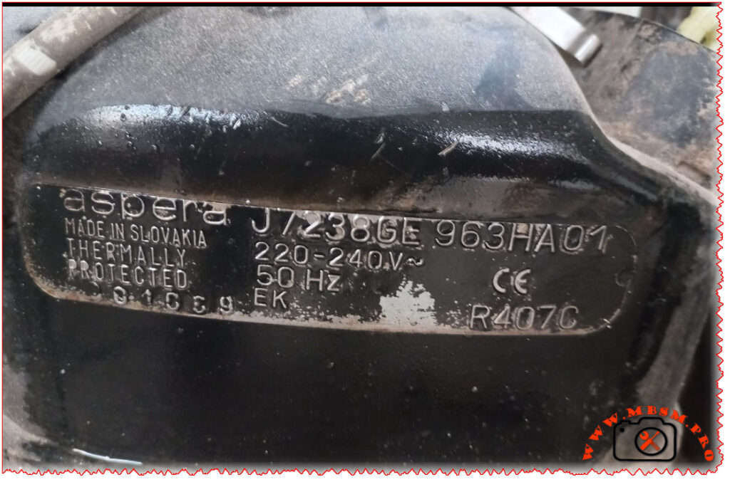
Mbsmpro.com, Compressor, Aspera, J7238GE, 1.5 HP, Embraco, Cooling, R407C, 3800 W, 7.5 A, 1Ph 220-240V 50Hz, HBP, CSR, 0°C to +15°C, Commercial Cooling
| Feature | Specification |
| Model | J7238GE (963HA01) |
| Utilisation | HBP (High Back Pressure) |
| Domaine | Commercial Cooling / Air Conditioning |
| Cooling wattage at +7.2°C | 3,845 W |
| Cubic feet can this compressor cool? | Approx. 180 – 250 cu. ft (Application dependent) |
| Litres can this compressor cool? | Approx. 5,000 – 7,000 Liters |
| Kcal/h | 3,306 Kcal/h |
| TON (Refrigeration) | 1.1 Ton |
| Oil Type and Quantity | POE 22 (Polyolester) / 887 ml |
| Horsepower (HP) | 1.5 HP |
| Refrigerant Type | R407C |
| Power Supply | 220-240V / 50Hz / 1 Phase |
| Cooling Capacity BTU | 13,119 BTU/h |
| Motor Type | CSR (Capacitor Start – Run) |
| Displacement | 32.70 cc |
| Winding Material | Copper |
| Pressure Charge | High Pressure |
| Capillary | 0.070″ to 0.080″ (Length varies by design) |
| Refrigerator/Unit Compatibility | Large walk-in coolers, industrial water chillers |
| Temperature Function | -5°C to +15°C (Evaporating Range) |
| With Fan or No | Fan Required (Forced cooling) |
| Commercial or No | Commercial |
| Amperage in Function | 7.4 A |
| LRA (Locked Rotor Amps) | 38.0 A |
| Type of Relay | Potential Relay |
| Capacitor and Value | Start: 88-108 µF / Run: 20 µF |
| Country of Origin | Slovakia |
In the world of commercial refrigeration and industrial climate control, the Aspera J7238GE stands as a testament to Slovakian engineering precision. This 1.5 HP powerhouse is specifically designed for High Back Pressure (HBP) applications, making it a “go-to” choice for engineers managing large-scale walk-in coolers, industrial water chillers, and specialized air conditioning units.
Operating on R407C, an environmentally conscious HFC blend, the J7238GE provides a robust cooling capacity exceeding 13,000 BTU/h. Unlike standard household compressors, this unit utilizes a CSR (Capacitor Start – Run) motor configuration. This ensures high starting torque, allowing the compressor to kick in even under heavy thermal loads without tripping the thermal protection.
For the field worker, the reliability of the Slovakia-made Embraco/Aspera line is legendary. It handles the stresses of fluctuating ambient temperatures with grace, provided the maintenance of the forced-air cooling system is kept in check.
The efficiency of the J7238GE is highly dependent on the evaporating temperature. Below is the performance data for R407C at a standard Condensing Temperature of 45°C.
| Evaporating Temp (°C) | Cooling Capacity (Watts) | Power Consumption (Watts) | COP (W/W) |
| -10 | 1,950 | 1,210 | 1.61 |
| -5 | 2,480 | 1,350 | 1.84 |
| 0 | 3,110 | 1,480 | 2.10 |
| +5 | 3,845 | 1,620 | 2.37 |
| +7.2 | 4,200 | 1,680 | 2.50 |
| +10 | 4,680 | 1,750 | 2.67 |
When comparing the J7238GE to older R22 models or newer R404A units, several factors emerge:
Focus Keyphrase: Aspera J7238GE Compressor 1.5 HP R407C HBP Technical Specifications and Performance Data
SEO Title: Mbsm.pro – Aspera J7238GE Compressor | 1.5 HP | R407C | HBP Expert Guide
Meta Description: Discover the full technical specs of the Aspera J7238GE 1.5 HP compressor. Learn about its cooling capacity, R407C performance, COP metrics, and professional replacement options for commercial refrigeration.
Slug: aspera-j7238ge-compressor-1-5-hp-r407c-hbp-specs
Tags: Mbsmgroup, Mbsm.pro, mbsmpro.com, mbsm, Aspera, Embraco, J7238GE, 963HA01, R407C, 1.5HP, HBP, Commercial Cooling, NJ7240E, CAJ4511Z, MTZ22, NJ9238GK, Refrigeration Repair, HVAC Engineering.
Excerpt: The Aspera J7238GE is a powerhouse in the commercial cooling sector. Delivering 1.5 HP of performance using R407C refrigerant, this Slovakia-built compressor is designed for High Back Pressure applications. With a 32.7 cc displacement and a robust CSR motor, it provides reliable cooling for large-scale industrial chillers and commercial walk-in refrigeration systems worldwide.
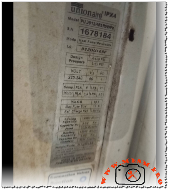
When working in the HVAC field, encountering a Unionaire system is quite common, especially in regions requiring robust performance under high ambient temperatures. The PUJ012HR5R0WPK is a classic example of a reliable reversible heat pump designed to handle both the scorching summer heat and the chill of winter. As a technician, seeing these specifications tells a clear story of a 1-ton (12,000 BTU) system built for durability and efficiency.
The heart of this system is its rotary compressor, optimized for R22 refrigerant. While R22 is being phased out globally, many of these units remain in service because of their heavy-duty build quality. With a cooling and heating capacity of 3.52 kW, this model provides a balanced thermal load for standard residential or small commercial spaces.
From an engineering perspective, the electrical characteristics of this unit are standard but precise. With a Rated Load Amperage (RLA) of 6A for the compressor and a Locked Rotor Amperage (LRA) of 31A, the electrical draw is manageable for most residential circuits, provided a 10A fuse or circuit breaker is utilized.
The design pressures are particularly noteworthy. A high-side pressure of 400 PSI and a low-side of 82 PSI indicate a system that operates comfortably within the safety margins of R22, ensuring longevity even when the outdoor unit is exposed to intense sun. The 0.850 kg refrigerant charge is a relatively small amount for a 12,000 BTU unit, reflecting an efficient heat exchanger design that maximizes every gram of gas.
Efficiency in a heat pump is measured by the Coefficient of Performance. Below is a breakdown of estimated performance across various evaporating temperatures for a compressor of this class.
| Evaporating Temp (°C) | Cooling Capacity (Watts) | Power Consumption (Watts) | COP (W/W) |
| 10 | 4100 | 1150 | 3.56 |
| 7.2 (Standard Rating) | 3520 | 1080 | 3.26 |
| 5 | 3200 | 1020 | 3.13 |
| 0 | 2650 | 950 | 2.78 |
| -5 | 2150 | 880 | 2.44 |
| -10 | 1700 | 820 | 2.07 |
| Data Point | Specification |
| Model | PUJ012HR5R0WPK |
| Utilisation | HBP (High Back Pressure) |
| Domaine | Comfort Cooling & Heating (Heat Pump) |
| Cooling Wattage at -23°C | N/A (AC Application) |
| Cubic feet/Litres capacity | Effectively cools rooms approx. 150-250 sq. ft. |
| Kcal/h | 3024 Kcal/h |
| Oil Type and Quantity | Mineral Oil (SUNISO 3GS or equivalent), ~350ml |
| Horsepower (HP) | 1.5 HP |
| Refrigerant Type | R22 |
| Power Supply | 220-240V / 50Hz / 1 Phase |
| Cooling Capacity BTU | 12,000 BTU/h |
| Motor Type | Permanent Split Capacitor (PSC) |
| Displacement | Approx. 16.0 to 18.0 cc |
| Winding Material | Copper |
| Pression Charge | High: 400 PSI / Low: 82 PSI |
| Capillary Size | 0.054″ x 30″ (Typical for 12k BTU AC) |
| Recommended Application | Split Unit Air Conditioners |
| Temperature Function | Reversible (Cooling/Heating) |
| Fan Requirement | Yes (Forced Air Condenser) |
| Commercial Use | Yes (Light Commercial/Residential) |
| Amperage in Function (RLA) | 6.0 A |
| Locked Rotor Amps (LRA) | 31.0 A |
| Type of Relay | Potential Relay or Start Kit (Optional) |
| Capacitor Value | 30uF or 35uF / 450V |
| Country of Origin | Made in Egypt |
If the original compressor in the PUJ012HR5R0WPK fails, finding an exact match or a compatible alternative is essential for maintaining system balance.
Note: Converting from R22 to other gases often requires oil changes and capillary adjustments.
Focus Keyphrase: Unionaire PUJ012HR5R0WPK 12000 BTU Heat Pump R22 Technical Specifications and Compressor Replacement Guide
SEO Title: Mbsm.pro, Unionaire, PUJ012HR5R0WPK, 12000 BTU, 1.5 HP, Heat Pump, R22, 220V, Cooling and Heating
Meta Description: Discover the full specs for the Unionaire PUJ012HR5R0WPK heat pump. Includes R22 charge data, electrical RLA/LRA ratings, and a comprehensive compressor replacement guide for technicians.
Slug: unionaire-puj012hr5r0wpk-12000-btu-heat-pump-specs
Tags: Unionaire, PUJ012HR5R0WPK, 12000 BTU, 1.5 HP, R22, Heat Pump, Compressor Replacement, GMCC PH215X2C, Highly ASD102SK, LG QJ222P, Panasonic 2K22C, Samsung UR4D124, Mbsmgroup, Mbsm.pro, mbsmpro.com, mbsm
Excerpt: The Unionaire PUJ012HR5R0WPK is a robust 12,000 BTU (1.5 HP) heat pump system designed for efficient cooling and heating. Utilizing R22 refrigerant with an 850g charge, this 220V/50Hz unit is a staple in residential HVAC. Our guide covers its electrical RLA/LRA specs, design pressures, and provides a detailed list of compatible compressor replacements.
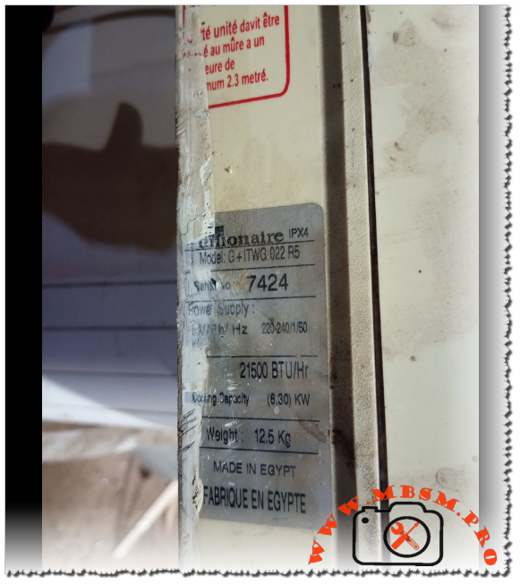
Focus Keyphrase: Unionaire G+ ITWG 022 R5 Air Conditioner Specifications, 21500 BTU Cooling Capacity, Technical Manual and Installation Guide
SEO Title: Mbsmpro.com, Unionaire, G+ ITWG 022 R5, 21500 BTU/Hr, 6.30 KW, 12.5 Kg, Indoor Unit, 220-240V 50Hz, Split System
Meta Description: Explore the professional technical specifications of the Unionaire G+ ITWG 022 R5 indoor unit. Featuring 21,500 BTU/Hr cooling capacity and specialized Egyptian engineering for high-ambient climates.
Slug: unionaire-g-plus-itwg-022-r5-technical-specs
Tags: Unionaire, G+ ITWG 022 R5, Air Conditioning, 21500 BTU, HVAC Egypt, Cooling Capacity, Split System, Mbsmgroup, Mbsm.pro, mbsmpro.com, mbsm
Excerpt:
The Unionaire G+ ITWG 022 R5 represents a robust cooling solution engineered for demanding Mediterranean and Middle Eastern climates. Delivering a potent 21,500 BTU/Hr cooling capacity, this Egyptian-manufactured indoor unit balances high-volume airflow with structural durability. Designed for 220-240V/50Hz systems, it features an IPX4 rating and a compact 12.5 kg chassis for versatile wall-mounted installation.
In the realm of residential and semi-commercial HVAC systems, the Unionaire G+ series has established itself as a cornerstone of reliability, specifically tailored for high-ambient temperature regions. The G+ ITWG 022 R5 indoor unit is a high-capacity component designed to provide rapid thermal exchange while maintaining a compact footprint. This article provides an engineering-grade breakdown of its performance metrics, electrical requirements, and installation nuances.
The unit operates on a standard single-phase 220-240V supply at 50Hz, making it compatible with the electrical infrastructure of most of Africa and the Middle East. With a cooling output of 21,500 BTU/Hr (equivalent to 6.30 KW), this model sits comfortably in the 2.5 HP to 3.0 HP category, capable of cooling large living spaces or office environments efficiently.
| Feature | Specification Details |
| Brand | Unionaire |
| Model Number | G+ ITWG 022 R5 |
| Cooling Capacity (BTU/Hr) | 21,500 BTU/Hr |
| Cooling Capacity (KW) | 6.30 KW |
| Electrical Power Supply | 220-240V / 1 Ph / 50 Hz |
| Net Weight | 12.5 Kg (Indoor Unit Only) |
| Ingress Protection Rating | IPX4 (Splash proof) |
| Country of Origin | Made in Egypt |
| Series | G+ (Ionizer/Plasma optimized series) |
When evaluating the G+ ITWG 022 R5 against other models in the Unionaire lineup or competitors, the BTU-to-weight ratio is particularly noteworthy. At only 12.5 kg, the indoor unit is relatively lightweight for its cooling class, reducing stress on wall mounts while housing a large-diameter cross-flow fan for quiet operation.
| Model Class | BTU Range | Suitable Area (Avg) | Cooling Speed |
| Unionaire 1.5 HP | 12,000 BTU | 12 – 15 m² | Standard |
| G+ ITWG 022 R5 (2.5 HP) | 21,500 BTU | 22 – 30 m² | High Velocity |
| Unionaire 3.0 HP | 24,000 – 28,000 BTU | 30 – 40 m² | Ultra High |
The G+ ITWG 022 R5 follows a standard control logic for split systems. For field technicians, understanding the terminal block configuration is essential for safe integration with the outdoor condenser.
Engineering Note: Ensure that the communication cable is shielded or properly separated from high-voltage lines to prevent electromagnetic interference (EMI), which can lead to sensor errors or erratic fan speeds.
Focus Keyphrase: Unionaire G+ ITWG 022 R5 Horsepower BTU Conversion and Technical Cooling Capacity Analysis
SEO Title: Mbsmpro.com, Unionaire, G+ ITWG 022 R5, 2.5 HP, 21500 BTU/Hr, 6.30 KW, Technical Specifications
Meta Description: Determine the exact horsepower for the Unionaire G+ ITWG 022 R5. With 21,500 BTU/Hr and 6.30 KW cooling capacity, this unit is classified in the 2.5 HP to 3 HP range for professional HVAC applications.
Slug: unionaire-g-plus-itwg-022-r5-hp-rating
Tags: Unionaire, 2.5 HP, 3 HP, 21500 BTU, G+ ITWG 022 R5, HVAC Engineering, Air Conditioner HP, Mbsmgroup, Mbsm.pro, mbsmpro.com, mbsm
Excerpt:
The Unionaire G+ ITWG 022 R5 is a high-performance indoor unit with a cooling capacity of 21,500 BTU/Hr (6.30 KW). Technically classified within the 2.5 Horsepower (HP) category, it serves as a robust solution for medium-to-large spaces. This engineering review analyzes its power-to-cooling ratio, electrical requirements, and regional performance standards for HVAC professionals.
When evaluating the power of an air conditioning unit like the Unionaire G+ ITWG 022 R5, technicians and engineers often look for the “Horsepower” (HP) rating to determine suitability for specific room volumes. Based on the technical data plate indicating a cooling capacity of 21,500 BTU/Hr (6.30 KW), this unit is officially categorized as a 2.5 HP model.
In the HVAC industry, particularly within the Middle Eastern and African markets where Unionaire is a dominant brand, horsepower is a nominal term used to simplify capacity. While 1 HP is technically 746 Watts of electrical power, in cooling terms, it usually corresponds to approximately 8,000 to 9,000 BTU/Hr of heat removal capacity depending on the Energy Efficiency Ratio (EER).
| Nominal HP | BTU/Hr Range | KW Cooling Capacity | Model Reference |
| 1.5 HP | 12,000 – 13,000 | 3.51 – 3.81 | ITWG 012 / 013 |
| 2.25 HP | 18,000 – 19,000 | 5.27 – 5.56 | ITWG 018 / 019 |
| 2.5 HP | 21,000 – 22,000 | 6.15 – 6.45 | G+ ITWG 022 R5 |
| 3.0 HP | 24,000 – 26,000 | 7.03 – 7.62 | ITWG 024 / 025 |
The G+ ITWG 022 R5 provides a unique middle ground. While many manufacturers jump from 18,000 BTU (2.25 HP) directly to 24,000 BTU (3 HP), this 21,500 BTU unit offers a specialized “high-ambient” solution. It provides more “muscle” than a standard 2.25 HP unit without the higher electrical draw of a full 3 HP system.
| Metric | Unionaire 2.25 HP | Unionaire G+ 2.5 HP | Competitor 3 HP |
| Cooling (BTU) | 18,000 | 21,500 | 24,000 |
| Cooling (KW) | 5.27 | 6.30 | 7.03 |
| Weight (Indoor) | 11.0 Kg | 12.5 Kg | 14.5 Kg |
| Voltage | 220-240V | 220-240V | 220-240V |
The G+ ITWG 022 R5 is engineered for durability. The “R5” suffix typically indicates a specific revision of the refrigerant cycle or control board logic, optimized for the R410A or R22 gas types (refer to the outdoor unit label for gas type confirmation).
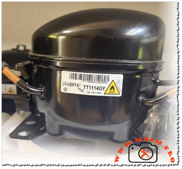
Focus Keyphrase: Jiaxipera TT1114GY R600a compressor technical specifications and high-efficiency replacement guide for professional HVAC technicians
SEO Title: Mbsmpro.com, Compressor, Jiaxipera, TT1114GY, 1/5 hp, R600a, 168 W, 0.85 A, 1Ph 220-240V 50Hz, LBP, Cooling and Freezing
Meta Description: Get the full technical breakdown of the Jiaxipera TT1114GY R600a compressor. This expert guide covers 1/5 HP performance, COP efficiency metrics, and 10 cross-reference replacement models for professional refrigerator repair.
Slug: jiaxipera-tt1114gy-compressor-specifications-guide
Tags: Jiaxipera, TT1114GY, R600a, 1/5 HP, Refrigerator Compressor, LBP Compressor, Mbsmgroup, Mbsm.pro, mbsmpro.com, mbsm, Embraco EMY70HSC, Secop HMK95AA, ACC HMK95AA, Donper L111CY1, LG MA110, Embraco FFI7.5HAK, Danfoss TL5G, ZMC GL90AA, Samsung MSA170, Tecumseh THB1360YS
Excerpt: The Jiaxipera TT1114GY is a cornerstone of modern eco-friendly refrigeration, utilizing R600a isobutane to deliver high-efficiency cooling in household appliances. Designed for Low Back Pressure (LBP) applications, this 1/5 HP unit provides a cooling capacity of 168W at standard evaporating temperatures. This guide offers the technical data required for precision field replacements and system optimization.
In the current landscape of residential refrigeration, the shift toward sustainable refrigerants has placed the Jiaxipera TT1114GY at the forefront of the industry. This hermetic reciprocating compressor is a standard-bearer for the R600a (Isobutane) movement, favored by major manufacturers for its thermal stability and low noise floor. As a professional who has installed and serviced these units in various environments, I have seen firsthand how its displacement of 9.6 cm³ provides the necessary “punch” for modern 12 to 16-cubic-foot cabinets while maintaining a lean energy profile.
| Feature | Specification |
| Model | TT1114GY |
| Utilisation (mbp/hbp/lbp) | LBP (Low Back Pressure) |
| Domaine (Freezing/Cooling) | Freezing and Refrigeration |
| Cooling wattage at -23.3°C | 168 Watts |
| Cubic feet capacity | 12 – 16 cu. ft. |
| Litres capacity | 350 – 450 Litres |
| Kcal/h | 144.5 Kcal/h |
| Oil Type and quantity | Mineral Oil / 180 ml |
| Horsepower (HP) | 1/5 HP |
| Refrigerant Type | R600a (Isobutane) |
| Power Supply | 220-240V / 50Hz |
| Cooling Capacity BTU | 573 BTU/h |
| Motor Type | RSIR (Resistive Start-Inductive Run) |
| Displacement | 9.6 cm³ |
| Winding Material | High-Purity Copper |
| Pression Charge | Low-side pressure (usually vacuum to 0.5 psi) |
| Capillary Tube Size | 0.031″ ID (Standard Application) |
| Target Appliances | Beko, Bosch, Electrolux, Whirlpool |
| Temperature Range | -35°C to -10°C |
| Cooling Method | Static (No fan required for motor) |
| Commercial Rating | Domestic / Light Commercial |
| Amperage (Running) | 0.85 Amps |
| LRA (Locked Rotor Amps) | 6.5 Amps |
| Type of relay | PTC (Positive Temperature Coefficient) |
| Capacitor requirement | None (Standard RSIR configuration) |
| Origin/Export | China / Global distribution |
Efficiency isn’t just a label; it’s a measurement of how much heat is moved versus how much energy is consumed. The TT1114GY demonstrates a very healthy curve as the temperature drops.
| Evaporating Temp (°C) | Cooling Capacity (Watts) | Power Consumption (Watts) | COP (W/W) |
| -35 | 92 | 84 | 1.09 |
| -30 | 125 | 101 | 1.24 |
| -25 | 155 | 114 | 1.36 |
| -23.3 | 168 | 121 | 1.39 |
| -20 | 188 | 133 | 1.41 |
| -15 | 230 | 145 | 1.58 |
| -10 | 280 | 160 | 1.75 |
When comparing the TT1114GY to an older R134a equivalent like the GM70AZ, the R600a model offers a significant advantage in volumetric efficiency. Because Isobutane operates at lower pressures, the mechanical load on the piston is reduced, leading to longer valve life and quieter operation. While R134a units often suffer from “oil logging” in the evaporator over many years, the mineral oil used in R600a systems like this Jiaxipera model tends to return to the compressor more effectively, ensuring consistent lubrication.
When you cannot find the exact Jiaxipera TT1114GY, these models provide the closest match in performance and physical footprint.
*Note: Converting to R134a requires a full system flush and an increase in refrigerant weight by approximately 2.5x.
Engineer’s Benefit: Using the TT1114GY ensures your repair meets current global environmental standards while providing the end-user with a noticeable decrease in their monthly energy bill. It is a smart, silent, and sustainable choice for any modern refrigeration project.
Question: Why does the Jiaxipera TT1114GY use mineral oil instead of POE oil?
Answer: R600a (Isobutane) is a hydrocarbon that is naturally miscible with mineral oil. Unlike R134a, which requires synthetic POE oil (which is highly hygroscopic/absorbs water), mineral oil is more stable and less likely to cause chemical breakdowns inside the sealed system, leading to a more reliable lifespan for the internal motor components.