Technical Troubleshooting: Automatic Washer Stops After Filling
Category: Global Electric
written by www.mbsmpro.com | January 30, 2026
Focus keyphrase: Troubleshooting Automatic Washer Stops After Filling Cycle
SEO Title: Mbsmpro, Troubleshooting, Automatic Washer, Stops After Filling, Water Level Switch, Lid Switch, Drain Motor, Error Codes
Meta Description: Is your washing machine dead silent after filling? Learn how to diagnose lid switches, pressure sensors, and drive motors like a pro. Expert repair guide for top and front loaders.
Tags: Mbsmgroup, Mbsm.pro, mbsmpro.com, mbsm, Washer Repair, Appliance Troubleshooting, Water Level Switch, Lid Switch Failure, DIY Repair, Washing Machine Maintenance
Excerpt: If your automatic washer fills with water but refuses to start the agitation or wash cycle, you are facing a common mechanical or electronic failure. This guide explores the primary culprits, including faulty lid switches, clogged pressure tubes, and failing drive motors, providing technical insights to help you diagnose and repair your appliance efficiently and safely.
Mbsmpro.com, Troubleshooting, Automatic Washer, Stops After Filling, Lid Switch, Pressure Sensor, Drive Motor, 110V-240V, 50/60Hz
When an automatic washer fills up but then sits in stony silence, it’s more than just an inconvenience—it’s a technical puzzle. As someone who has spent years in the field with a multimeter in hand, I can tell you that this specific symptom usually points to a break in the “logical sequence” of the machine’s controller.
The Anatomy of the Failure
For a washer to transition from the Fill Stage to the Wash Stage, specific electrical conditions must be met. If the control board doesn’t receive a “Go” signal from the sensors, the timer will stall.
Primary Technical Culprits
Component
Function
Failure Symptom
Lid Switch / Door Lock
Safety interrupt for the motor circuit.
Machine fills but won’t agitate or spin.
Water Level Switch
Detects air pressure from the tub.
Machine keeps filling or stops without starting motor.
Drive Motor / Capacitor
Provides mechanical rotation.
Hum sounds but no movement; dead silence if open circuit.
Drive Belt
Transfers power from motor to drum.
Motor runs (hums/whirs) but the drum is stationary.
Deep Dive: The Water Level Pressure Switch
The most common reason a machine stops after filling is that it doesn’t know it’s full. A small transparent tube connects the outer tub to a pressure switch. If this tube is clogged with “scrub” (detergent gunk) or has a pinhole leak, the diaphragm inside the switch won’t trip the electrical contact to the motor.
Technical Comparison: Pressure Switch vs. Hall Effect Sensor
Feature
Mechanical Pressure Switch
Electronic Hall Effect Sensor
Signal Type
Discrete (On/Off)
Analog/Digital Frequency
Reliability
Prone to contact pitting
Highly reliable but sensitive to moisture
Common Use
Traditional Top Loaders
Modern Inverter Front Loaders
Voltage
Usually 120V/240V AC
5V – 12V DC
The “Lid Switch” Logic
In most American-style top loaders, the lid switch is wired in series with the motor. If the plastic tab on your lid is broken, or the internal switch has failed due to arcing, the machine will fill perfectly (as the water valves are on a different circuit) but will never “click” over to start the motor.
Engineering Insight: Always check for continuity across the lid switch terminals using a multimeter. If the resistance is infinite ($\infty \Omega$) when the switch is depressed, the component is defective.
Wiring Schematic Concept
For technicians, the circuit usually follows this path:
L1 (Hot) -> Timer/Main Board -> Water Level Switch (Full Position) -> Lid Switch -> Motor Start Capacitor -> Main Motor -> Neutral.
Pro-Tips and Maintenance Notices
The “Blow” Test: If you suspect the water level switch, disconnect the small tube from the tub side and blow gently into it toward the switch. You should hear a distinct “click.” If you don’t, the diaphragm is ruptured.
Capacitor Health: If the motor hums but doesn’t turn, the Start Capacitor is likely weak. Check the microfarad ($\mu F$) rating against its label.
Safety First: Always disconnect the power supply before testing internal components. Water and electricity are a lethal combination.
Engineer’s Note: Modern “High Efficiency” (HE) machines may stop and “sense” for several minutes. Do not confuse a sensing pause with a mechanical failure. Check for error codes (e.g., F8 E1 or LF) on the digital display.
Technical Troubleshooting: Automatic Washer Stops After Filling mbsmpro
our decision to stay away from these four brands (Kriazi, Candy, GMC, White Whale) may be based on past experiences or technical advice related to the availability of spare parts, the quality of after-sales service, or the lifespan of electronic components.
In the professional appliance sector, choosing a washing machine is an engineering audit, not a simple shopping trip. As a field expert who has dismantled thousands of units and performed rigorous stress tests on drive systems, I look beyond the digital displays to the mechanical heart of the machine: the drum bearings, the motor windings, and the electrolytic capacitors on the control board.
Technical data from the field indicates a significant divergence in quality. While some brands focus on high-turnover consumer goods, others invest in Structural Integrity. If you are being advised to “stay away” from Kiryazi, Candy, GMC, and White Whale, it is not a matter of brand bias—it is a matter of documented mechanical fatigue and specialized component scarcity.
Technical Breakdown: Identifying the Structural Bottlenecks
When an appliance fails, it is usually due to a “weakest link” in its design. Here is the professional technical breakdown of why these four brands often face professional criticism from repair engineers:
Kiryazi (Structural Oxidation): The primary issue lies in the galvanization process of the outer cabinet. In many models, the steel gauge is insufficient, leading to premature rust around the detergent drawer and base, which eventually compromises the machine’s balance during high-RPM cycles.
Candy (Electronic Volatility): Candy machines often feature highly sophisticated integrated circuits. However, the PCB (Printed Circuit Board) lacks robust thermal shielding. In environments with fluctuating voltage, the microprocessor is prone to “logic hanging” or total failure.
GMC (Mechanical Friction): Many GMC models rely on traditional Universal Brush Motors. These motors generate significant carbon dust and heat, leading to shorter lifespans for the drive belt and much higher decibel levels during the spin cycle.
White Whale (Component Inconsistency): The “Spider” assembly (the three-arm support for the drum) in these units is frequently made of a low-grade Zinc-Aluminum alloy. This material reacts chemically with liquid detergents, leading to “pitting corrosion” and eventual drum detachment.
Engineering Comparison: High-Tier vs. Standard Tier
To make an informed decision, we must compare the Material Science and Drive Systems of industry leaders against standard budget models.
Technical Component
Standard Group (Avoid)
LG (Direct Drive)
Samsung (Inverter)
Bosch (Series 6/8)
Motor Tech
Universal Carbon Brush
Brushless DC (BLDC)
Digital Inverter
EcoSilence Drive
Drive Logic
Mechanical Pulley
Direct Coupling
Reinforced Ribbed Belt
High-Torque Belt
Bearing Seal
Single Lip
Double-Lip / Viton
High-Temp Synthetic
Industrial Grade
PCB Protection
Basic Varnish
Resin Encapsulation
Moisture Shield
Thermal Management
Vibration Control
Standard Springs
6-Motion AI
VRT Plus (Ball Balance)
AntiVibration Walls
The Inverter Logic: Electronic Schematic of Superiority
For the technician, the shift to Inverter Technology (found in LG, Samsung, and Bosch) is the greatest leap in reliability. Unlike the simple “On/Off” relay logic of older GMC or Kiryazi units, modern systems utilize a Variable Frequency Drive (VFD) logic path:
Rectification Stage: Incoming AC is converted to stable DC power.
IGBT Switching: (Insulated Gate Bipolar Transistors) pulse the power to the motor windings.
Frequency Modulation: By changing the electrical frequency, the machine controls torque and speed with extreme precision, without mechanical stress.
Result: This eliminates the Carbon Brushes, which are the primary wear-and-tear component in traditional washing machines.
Field Values: Performance Comparison Metrics
Performance Feature
Budget Brands (Kiryazi/GMC)
Premium Engineering (LG/Bosch)
Spin Decibels
76 dB – 82 dB
48 dB – 54 dB
Thermal Cut-out
Frequent (friction-based heat)
Rare (active cooling logic)
Drum Balance
Passive (Weight-based)
Active (Sensor-based)
Parts Availability
Fragmented / Generic
Serialized / Global
Professional Councils and Maintenance Protocols
Advice on Installation: Never place a washing machine on a wooden floor or an unlevel surface. For Bosch and LG units, precision leveling is required to allow the internal accelerometers to calibrate the “Zero-Point” vibration correctly.
Notice on Detergent: Excessive use of “Soap Powder” causes a buildup known as “Scrud.” In White Whale and Candy models, this acidic sludge accelerates the decay of the drum seal.
The Benefit of Direct Drive: By removing the belt, LG has eliminated a major friction point, significantly reducing energy loss and increasing the motor’s life expectancy to over a decade.
Final Technical Verdict
The recommendation to avoid Kiryazi, Candy, GMC, and White Whale is based on the Mean Time Between Failures (MTBF) observed in the field. As an engineer, I recommend prioritizing brands that utilize Resin-Encapsulated Electronics and Brushless Motors. LG, Samsung, and Bosch provide the necessary Mechanical Tolerance to handle the stresses of modern laundry requirements.
Focus keyphrase: Technical engineering review of washing machine brands explaining why LG Samsung and Bosch are superior to Kiryazi Candy GMC and White Whale for long-term durability.
Meta description: Expert engineering analysis on washing machine durability. Discover why technicians recommend LG, Samsung, and Bosch over Kiryazi, Candy, GMC, and White Whale for long-term use.
Tags: Mbsmgroup, Mbsm.pro, mbsmpro.com, mbsm, Washing Machine Repair, LG Direct Drive, Bosch EcoSilence, Samsung Inverter, Appliance Engineering, Inverter Motor Schematic, Drum Bearing Failure.
Excerpt:A washing machine is a long-term engineering investment. From a field technician’s perspective, choosing the right brand depends on mechanical durability and electronic stability. While brands like Kiryazi, Candy, GMC, and White Whale are popular, they often face structural oxidation and PCB failures. This article analyzes why LG, Samsung, and Bosch are technically superior.
Stay away from 4 washing machines: Kiriazi, Candy, GMC, White Whale mbsmpro
MCB miniature circuit breaker thermal magnetic protection mechanism
Category: Global Electric
written by www.mbsmpro.com | January 30, 2026
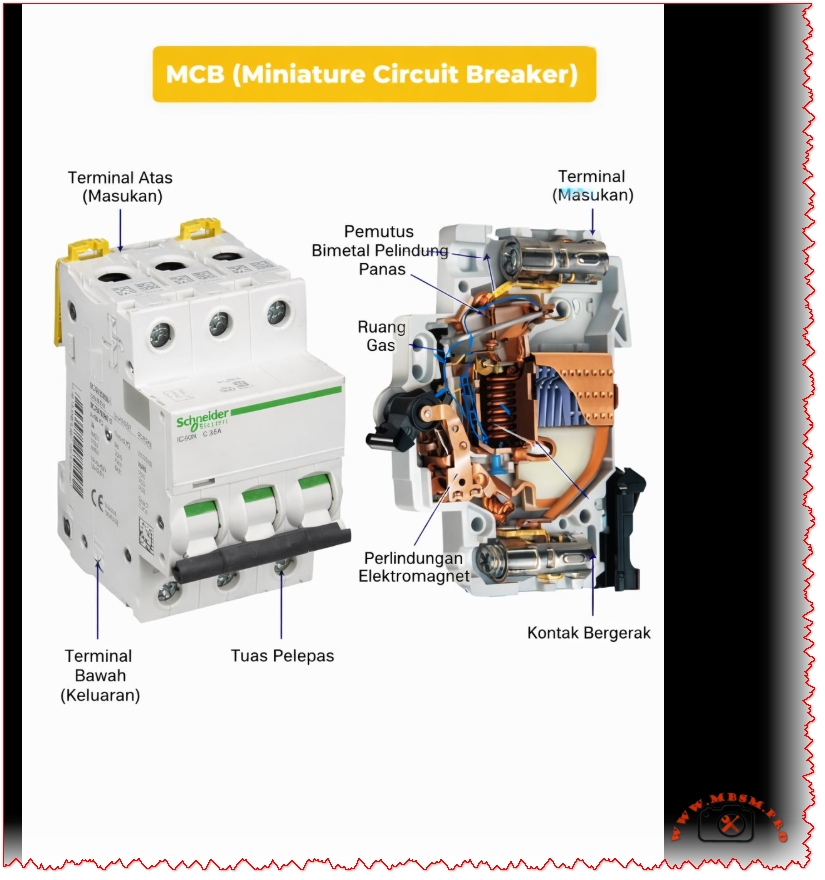
MCB (Miniature Circuit Breaker): Complete Guide to Thermal Magnetic Protection Technology
FOCUS KEYPHRASE (Max 191 characters)
MCB miniature circuit breaker thermal magnetic protection mechanism bimetallic overload short circuit electrical safety
META DESCRIPTION (155-160 characters)
Discover how MCB miniature circuit breakers work with thermal-magnetic protection. Complete technical guide to overload and short-circuit safety mechanisms.
An MCB (Miniature Circuit Breaker) is an automatic electrical switch that protects circuits from overloads and short circuits. Using dual thermal-magnetic mechanisms, MCBs detect abnormal currents and instantly disconnect power to prevent equipment damage and fire hazards. Compact, reliable, and essential for modern electrical safety.
MCB (Miniature Circuit Breaker): The Complete Technical Guide to Thermal-Magnetic Protection
Introduction: What is an MCB?
An MCB (Miniature Circuit Breaker) represents one of the most critical innovations in electrical safety systems. This automatic protective device safeguards residential, commercial, and industrial electrical installations by instantly interrupting power flow when dangerous conditions occur. Unlike traditional fuses that require replacement, modern MCBs offer reusable, reliable protection through intelligent dual-mechanism technology.
The primary function of an MCB is straightforward yet vital: detect abnormal electrical conditions and automatically isolate the circuit before damage occurs. Whether protecting a household appliance or industrial machinery, MCBs serve as the first line of defense against electrical hazards.
How MCB Works: Understanding the Dual Protection System
The Thermal Protection Mechanism
The thermal component of an MCB employs a sophisticated bimetallic strip—a thin metal band created by bonding two different metals together. These metals possess different thermal expansion coefficients, meaning they expand at different rates when heated.
The thermal process operates as follows:
Normal Operation – Under rated current conditions, heat generation is minimal. The bimetallic strip remains relatively straight.
Overload Detection – When current exceeds the MCB’s rated capacity, excessive heat causes unequal expansion between the two bonded metals.
Strip Deflection – The differential expansion forces the bimetallic strip to bend or curve progressively.
Mechanical Latch Release – Once the strip bends sufficiently, it physically releases a mechanical latch mechanism.
Contact Separation – The released latch triggers the operating mechanism to open the electrical contacts, stopping current flow.
Key Characteristic: Thermal protection provides delayed response, making it ideal for sustained overload situations lasting seconds to minutes.
The Magnetic Protection Mechanism
While thermal protection handles gradual overloads, magnetic protection addresses immediate threats from short circuits.
Inside each MCB exists a solenoid coil (electromagnet) that surrounds the electrical contacts. When current flows normally, the magnetic field strength remains insufficient to trigger action.
The magnetic response sequence:
Short Circuit Occurrence – A fault suddenly causes current to spike to dangerous levels (often 10-100 times the rated current).
Magnetic Field Generation – The solenoid coil creates an intense electromagnetic field proportional to current magnitude.
Armature Attraction – This powerful magnetic field attracts an armature (movable iron piece) at lightning speed.
Instant Contact Opening – The armature movement triggers an override mechanism that forces electrical contacts open within milliseconds.
Arc Suppression – Specialized components called arc contacts and gas-filled chambers extinguish any electrical arc that forms during contact separation.
Key Characteristic: Magnetic protection provides instantaneous response (typically 10-50 milliseconds), protecting against catastrophic short-circuit damage.
MCBs come in standardized current ratings, each suited to specific applications:
MCB Rating (Amperes)
Typical Application
Common Use
0.5A – 2A
High-sensitivity circuits
Lighting, low-power sensors
3A – 6A
General lighting circuits
Residential household lighting
10A – 13A
Standard domestic circuits
Appliances, outlets, general power
16A – 20A
Heavy-duty domestic use
Kitchen appliances, water heaters
25A – 32A
Industrial and commercial
Industrial machinery, heavy loads
40A – 63A
Large installations
Industrial production lines
80A – 125A
Main distribution systems
Building main switchboards
Expert Recommendation: Select MCB ratings based on wire gauge and actual load requirements, not convenience. Undersized MCBs trip frequently; oversized units provide inadequate protection.
Voltage Specifications
MCBs operate within defined voltage ranges:
Single-Phase MCBs: 230V (standard residential in most countries)
Three-Phase MCBs: 400V (industrial applications)
Dual-Voltage Models: Can operate at both 230V and 400V
Breaking Capacity (Interrupting Rating)
This critical specification indicates the maximum short-circuit current an MCB can safely interrupt without sustaining damage. Measured in kiloamperes (kA), breaking capacity values typically range from 3 kA to 25 kA:
Breaking Capacity
Application Suitability
Typical Environment
3 kA – 6 kA
Lightweight residential use
Modern suburban homes, low-fault areas
10 kA
Standard domestic/commercial
Typical apartment buildings, offices
15 kA – 25 kA
Industrial and high-fault areas
Factories, power-dense facilities
Critical Safety Note:Never install an MCB with insufficient breaking capacity for your electrical system’s fault level. Exceeding breaking capacity causes dangerous failure.
MCB Curve Types: Matching Protection to Application
MCBs employ different tripping characteristics, designated by letters B, C, and D. Each curve represents how quickly the MCB responds to different multiples of rated current:
Type B Curve MCBs
Magnetic Trip Threshold: 3–5 times rated current
Optimal For: Purely resistive loads with minimal inrush current
Applications: Incandescent lighting, resistive heaters, general residential wiring
Response Time: Fast, but slightly delayed for transient spikes
Type C Curve MCBs(Most Common in Residential/Commercial)
Magnetic Trip Threshold: 5–10 times rated current
Optimal For: Mixed loads with moderate inrush currents
Applications: Standard household circuits, office equipment, small motors, the most versatile choice
Response Time: Balanced between nuisance tripping and protection
Industry Standard: Nearly universal choice for general-purpose installations
Type D Curve MCBs
Magnetic Trip Threshold: 10–20 times rated current
Optimal For: Loads with high inrush currents
Applications: Large motors, transformers, industrial machinery, welding equipment, compressors
Response Time: More forgiving of startup transients, essential for heavy industrial loads
Comparison Table: MCB Curve Selection
Characteristic
Type B
Type C
Type D
Magnetic Sensitivity
Very High (3–5×)
Medium (5–10×)
Low (10–20×)
Residential Use
Specific applications
General standard
Rare
Commercial Use
Limited
Standard
Industrial
Motor Protection
Poor
Fair
Good
Inrush Tolerance
Minimal
Moderate
High
Cost
Low
Low
Moderate
Reliability
Good
Excellent
Good
Thermal vs. Magnetic Protection: Complementary Systems
The brilliance of MCB design lies in combining these two protection mechanisms, each handling distinct fault scenarios:
When Does Thermal Protection Activate?
Thermal protection engages during gradual overload conditions:
Current exceeds rated value but remains below magnetic threshold
Heat gradually accumulates in the bimetallic strip
Activation Time: 5 seconds to several minutes depending on overload magnitude
Magnetic protection engages during sudden, catastrophic faults:
Current spikes instantly to dangerous levels (short circuits, direct faults)
Electromagnetic field builds instantly
Activation Time: 10–50 milliseconds (near-instantaneous to human perception)
Examples: Touching live wires, equipment short circuits, electrical arcing, damaged insulation allowing conductors to contact each other
Synergistic Protection Table
Scenario
Thermal Response
Magnetic Response
Outcome
Overloaded circuit (sustained)
✓ TRIGGERS
– Remains inactive
MCB trips safely
Short circuit (sudden)
– Inactive
✓ TRIGGERS
Instant protection
High inrush current (motor start)
– Tolerates
– Tolerates (if Type C/D)
No false trips
Combination overload + fault
✓ TRIGGERS
✓ TRIGGERS
Redundant protection
MCB vs. MCCB: Understanding the Key Differences
Confusion often arises between MCBs and MCCBs (Molded Case Circuit Breakers). While both protect circuits, they serve fundamentally different applications:
When bonded together and heated, differential expansion forces the assembly to curve. This design allows precise calibration: engineers adjust strip thickness, length, and material composition to achieve exact trip temperatures for specific current ratings.
Solenoid Coil Specifications
The electromagnet comprises:
Copper Wire Winding – Typically 500–1,000 turns depending on design
Soft Iron Core – Concentrates magnetic field for maximum strength
Precise Calibration – Coil parameters engineered to trigger at exact current multiples
Electrical Contacts
MCBs employ specialized contacts:
Main Contacts – Silver-plated for electrical conductivity and corrosion resistance
Arc Contacts – Harder metals (tungsten or molybdenum) that resist electrical erosion
Arc Suppression Chamber – Quartz sand or gas chamber that cools and extinguishes arcs during contact separation
Contact Material Longevity – Typically 10,000+ mechanical operations before replacement consideration
Installation Best Practices: Expert Recommendations
Critical Safety Considerations
1. Proper Circuit Protection Coordination
MCBs must be strategically sized:
Consideration
Guideline
Rationale
Wire Gauge Matching
MCB rating ≤ wire ampacity
Prevents wire overheating before MCB trips
Selective Coordination
Downstream MCBs trip first
Isolates faults to affected circuit only
Load Calculation
Sum actual amperes + 25% safety margin
Accounts for seasonal variations, equipment aging
2. Ambient Temperature Compensation
MCB performance varies with temperature:
High Temperatures (>40°C): Thermal element becomes more sensitive; may trip prematurely on normal loads
Low Temperatures (<20°C): Reduced sensitivity may delay thermal tripping
Solution: Select MCBs with ambient temperature ratings appropriate for installation environment
3. Curve Selection Validation
Test inrush currents before installation:
Measure startup currents of motors and transformers
Compare against MCB curve trip thresholds
Ensure adequate margin to prevent nuisance tripping
Installation Sequence
Power Isolation – Ensure main supply disconnection and lockout/tagout procedures
DIN-Rail Preparation – Install on properly grounded DIN rail at 35mm width nominal
Clearance Verification – Ensure minimum 25mm clearance between pole terminals
Labeling – Permanently mark circuit identification on MCB or adjacent labeling
Testing – Verify manual trip mechanism and test circuit integrity before energization
Common MCB Failures: Diagnosis and Prevention
Premature or Nuisance Tripping
Symptom: MCB repeatedly trips without apparent overload
Possible Causes:
Undersized MCB for actual circuit load
Inrush current from motor/transformer exceeding Type C tolerance
Moisture infiltration or environmental stress
Internal mechanical wear after years of service
Solutions:
Calculate actual circuit load accurately and upsize appropriately
Switch to Type D MCB if high-inrush loads present
Ensure panel installation in dry, temperature-controlled environment
Replace MCB if mechanical wear suspected
Failure to Trip (Safety Hazard)
Symptom: Dangerous overload or short circuit occurs without MCB response
Possible Causes:
Undersized breaking capacity for fault current level
Contact welding from arc damage
Mechanical jamming or corrosion
Electromagnetic coil failure
Critical Action:Immediately disconnect circuit and replace MCB. This represents serious safety risk.
Thermal Drift or Inconsistent Performance
Symptom: MCB trips at different current levels depending on temperature or recent history
Possible Causes:
Bimetallic strip metal fatigue from repeated heating cycles
Environmental temperature extremes affecting thermal sensitivity
Interaction between thermal and magnetic mechanisms during simultaneous stress
Resolution: Replacement with fresh MCB or upgrade to premium models with enhanced thermal stability.
Advantages of Modern MCB Technology
Superior Safety Profile
✓ Automatic Response – Eliminates human error inherent with manual switches ✓ Dual Protection – Simultaneously protects against overload and short-circuit hazards ✓ Arc Containment – Suppresses dangerous electrical arcing within device ✓ Fire Prevention – Eliminates arc-induced fires common with older protection methods
Operational Benefits
✓ Reusable – Simple manual reset vs. fuse replacement ✓ Compact Design – Space-efficient compared to older switches ✓ Fast Response – Magnetic protection responds in milliseconds to short circuits ✓ Visual Indication – Handle position clearly shows ON/OFF/TRIPPED status
Economic Advantages
✓ Long Lifespan – 10,000+ mechanical operations typical ✓ Low Maintenance – No periodic adjustment or recalibration required ✓ Minimal Replacement Cost – €3–15 vs. industrial circuit breaker costs ✓ Reduced Downtime – Instant reset vs. fuse procurement and installation delay
Compatibility and Flexibility
✓ Standardized Mounting – Industry-standard DIN-rail compatibility ✓ Modular Design – Mix single, double, triple-pole configurations ✓ Curve Selection – Type B, C, D options for different load characteristics ✓ Retrofit Capability – Replace older protection systems without major reconstruction
Specialized MCB Variants: Advanced Protection
RCBO (Residual Current Breaker with Overcurrent Protection)
An RCBO combines MCB functionality with residual current detection:
Additional Feature: Detects current imbalance between live and neutral conductors
Protection Against: Electric shock, particularly in wet environments (bathrooms, kitchens, outdoors)
Sensitivity: Typically 30mA (milliampere) trip threshold
Standards: IEC 61008, European standard for shock protection
RCBO vs. Standard MCB:
Aspect
Standard MCB
RCBO
Overload Protection
✓ Yes
✓ Yes
Short Circuit Protection
✓ Yes
✓ Yes
Electric Shock Protection
✗ No
✓ Yes
Wet Location Suitability
Poor
Excellent
Cost
Low
Higher
Complexity
Simple
Advanced
Earth Leakage Circuit Breaker (ELCB)
Older technology now largely replaced by RCBO:
Detects current leakage to earth (ground)
Less precise than modern residual current detection
Still found in some legacy installations
Recommendation: Upgrade to RCBO for superior protection
MCB Selection Guide: Practical Decision Tree
Step 1: Determine Application Type
textIs this installation...?
├─ Residential (home) → Go to Step 2A
├─ Commercial (office/retail) → Go to Step 2B
└─ Industrial (factory/heavy equipment) → Consider MCCB instead
Step 2A: Residential Circuit Calculation
For each circuit:
Identify all connected devices (lights, outlets, appliances)
Look up power ratings (typically labeled in watts or amps)
Calculate total: Sum all amps for simultaneous operation
Add 25% Safety Margin: Multiply by 1.25
Select MCB: Choose standard rating ≥ calculated value
Compliance Verification: Check for certification marks on MCB body (CE, UL, RoHS symbols indicating standards compliance).
Maintenance and Lifecycle Management
Routine Inspection Protocol
Quarterly:
Visual inspection for corrosion, discoloration, or damage
Verify handle moves freely in ON/OFF positions
Check panel labeling remains legible
Annually:
Test trip mechanism by manually switching to OFF position
Restore to ON; confirm circuit continuity
Document any sluggish operation requiring investigation
Every 5 Years:
Professional inspection by qualified electrician
Electrical testing to verify trip thresholds
Thermal imaging to detect anomalous heating
Replacement of any questionable units
End-of-Life Recycling
MCBs contain valuable copper and recyclable materials:
Separate from general electrical waste
Contact local hazardous waste facilities for proper disposal
Some suppliers offer collection/recycling programs
Never dispose in standard trash
Conclusion: MCBs as Essential Electrical Protection
The humble MCB represents decades of electrical engineering refinement, delivering robust protection at minimal cost. Understanding thermal-magnetic operation, curve selection, and proper installation transforms MCBs from mysterious “boxes that interrupt power” into intelligible safety components perfectly matched to specific applications.
Key Takeaways:
✓ Thermal protection safeguards against gradual overloads ✓ Magnetic protection provides instantaneous short-circuit defense ✓ Proper sizing balances protection with operational reliability ✓ Curve selection must match load inrush characteristics ✓ Professional installation ensures system safety and code compliance
Whether protecting a home’s light switches or a factory’s motor controllers, MCBs serve as the foundation of modern electrical safety—silent guardians performing their critical function reliably for decades.
Additional Resources from Mbsmpro.com
For specialized technical documentation on electrical protection systems, equipment specifications, and HVAC component integration, visit Mbsmpro.com—your comprehensive resource for professional-grade technical information and industry expertise.
MCB miniature circuit breaker thermal magnetic protection mechanism mbsmpro
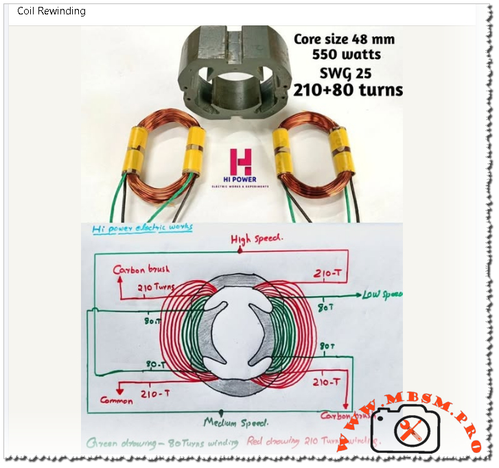
Coil rewinding for small universal motors, such as mixer grinder motors with a 48 mm laminated core and 550‑watt rating, demands precise control of turns, wire gauge, and internal connections. When done correctly, a rewound motor can match or even improve the original performance, while poor technique quickly leads to overheating, sparking, or speed loss.
Technical Overview of 550 W Universal Motor Rewinding
A typical 550‑watt mixer‑grinder uses a two‑pole universal motor with separate field coils and a wound armature, designed for very high speed and strong starting torque. For the 48 mm core shown, common practice is to wind each field with 210 primary turns plus an additional 80 turns using SWG 25 copper wire, giving a combined 210+80 configuration.
Parameter
Typical value for this motor
Engineering note
Core size
48 mm stack height
Determines space for copper and magnetic flux path.
Output rating
550 watts (universal motor)
Suited for mixer grinders and similar appliances.
Wire gauge
SWG 25 enamel copper
Compromise between current capacity and slot fill.
Turns per field
210 turns main + 80 turns auxiliary
Adjusts flux for multi‑speed operation.
Supply type
AC mains with commutator brushes
Universal design allows AC or DC use.
From an engineering point of view, keeping the original turns count and SWG is critical, because these define magnetizing current, torque, copper loss, and temperature rise for the motor.
High, Medium, and Low Speed Winding Connections
Multi‑speed mixer grinders often use the same physical coils but connect them differently through the selector switch to change the effective number of active turns and the series/parallel configuration. The diagram referenced for this 550 W motor shows two colored windings per field: red for 210‑turn sections and green for 80‑turn sections, arranged symmetrically around the stator.
Speed position
Active field turns
Typical connection logic
Effect on performance
High speed
Mainly 210‑turn sections between carbon brushes and common
Lower effective field flux, higher speed but less torque per amp.
Medium speed
210 + 80 turns in series on each side
Higher flux than high speed, moderate speed and torque.
Low speed
Emphasis on 80‑turn sections combined to increase net turns and resistance
Highest field flux, lower speed but stronger load handling and softer start.
Compared with simple single‑speed universal motors, this multi‑tap field arrangement gives finer control of torque and speed without using complex electronic drives, which is ideal for domestic appliances where rugged mechanical selection is preferred.
Engineering Comparison: Universal Motor Rewinding vs Induction Motor Rewinding
Although both tasks are labeled coil rewinding, the engineering approach differs significantly between universal motors and three‑phase induction motors.
Aspect
Universal motor (mixer grinder)
Three‑phase induction motor
Core type
Laminated stator with salient poles and series field coils.
Slotted stator with distributed three‑phase windings.
Windings to rewind
Field coils and armature coils with commutator segments.
Only stator coils in most cases; rotor is squirrel cage.
Turns & gauge
Often high turns with relatively fine wire (e.g., SWG 25), tailored for high speed.
Fewer turns of thicker conductors sized for phase current and duty cycle.
Speed control
By field taps, series/parallel connections, or electronic control.
By supply frequency and pole number; rewinding changes pole count or voltage.
Induction motor rewinding relies heavily on slot geometry, phase grouping, and pole pitch, as explained in best‑practice manuals, while universal motor rewinding demands careful routing around the commutator and precise brush alignment for spark‑free operation.
Professional Rewinding Practices and Practical Conseil
Rewinding high‑speed universal motors for appliances requires both electrical knowledge and good workshop discipline. Some key consel for technicians and engineers:
Copy the original design closely. Measure turns, wire SWG, and connection order before stripping the old winding; best‑practice guides emphasize copying coil pitch, turns, and copper cross‑section to keep performance consistent.
Keep coil overhang compact. Minimize the length of end turns to reduce I²R loss and keep the motor cool, as recommended for all motor rewinds.
Balance both sides of the stator. Universal motors are sensitive to magnetic asymmetry; ensure that each pole pair carries identical turns and uses the same direction of winding.
Secure insulation and impregnation. Use proper slot liners, phase separators, and varnish curing so that coils withstand vibration and high centrifugal forces at full speed.
Check commutator and brushes. After rewinding, undercut mica, true the commutator, and seat the brushes to avoid heavy sparking during high‑speed operation.
Following these engineering‑grade steps makes the rewound 550‑watt mixer‑grinder motor safe, efficient, and durable in demanding kitchen or workshop environments.
Focus keyphrase (Yoast SEO) coil rewinding 550 watt universal motor 48 mm core SWG 25 210 plus 80 turns mixer grinder field coil high medium low speed connection diagram
SEO title Mbsmpro.com, Coil Rewinding, 550 W Universal Motor, 48 mm Core, SWG 25, 210+80 Turns, Mixer Grinder Field Coil, High–Medium–Low Speed
Meta description Technical guide to rewinding a 550 W universal mixer‑grinder motor with 48 mm core, SWG 25 wire, and 210+80 turn field coils, including speed connections, engineering comparisons, and professional workshop tips.
Tags coil rewinding, universal motor winding, mixer grinder field coil, SWG 25 wire, 210+80 turns, multi speed motor, motor rewinding tips, electric motor repair, Mbsmgroup, Mbsm.pro, mbsmpro.com, mbsm
Excerpt (first 55 words) Coil rewinding for a 550‑watt universal mixer‑grinder motor with a 48 mm core is more than just replacing burnt copper. The technician must reproduce the original 210+80 turn field coils with SWG 25 wire, respect the high‑medium‑low speed connections, and follow best rewinding practices to keep torque, speed, and temperature under control.
10 PDF or technical resources about motor and coil rewinding
Mixer‑grinder field coil winding and connection details for 550 W, 48 mm core, including 210+80 turn information (Hi Power Electric Works post and shared diagrams).
General best‑practice manual “Best Practice in Rewinding Three Phase Induction Motors”, covering stripping, inserting, connecting, and insulating new coils.
AC motor winding diagrams collection, explaining slot distribution, coil grouping, and phase relationships.
Technical catalog of coil‑winding machines and accessories used for precision winding of small motors and transformers.
Leroy‑Somer documentation on winding and unwinding solutions with analog references, focused on tension and speed control in coil production.
Guide on calculating Standard Wire Gauge (SWG) for motor windings, including formulas linking current, voltage, and wire size.
General catalog of winding, measuring, and warehouse systems, including manual coil and spool winders.
PDF manual “Rewinding 3‑Phase Motors” that details mathematical rules for windings, torque, and flux, useful for understanding rewinding principles.
Technical catalog for IMfinity three‑phase induction motors, providing background on motor design and winding data for comparison.
Various educational documents and diagrams on AC motor winding available through motor‑winding training PDFs and diagram references similar to the AC motor winding document cited above.
Coil Rewinding, Universal Motor, 550 W mbsmpro
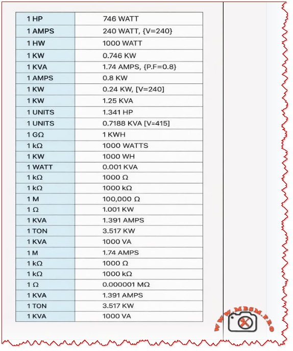
Electrical unit conversion reference table: HP to watts, KVA to amps, tons refrigeration to kW
Category: Global Electric
written by www.mbsmpro.com | January 30, 2026
COMPREHENSIVE ELECTRICAL AND REFRIGERATION UNIT CONVERSION GUIDE: Complete Reference for HVAC Professionals and Engineers
SEO METADATA
Focus Keyphrase (191 characters max): Electrical unit conversion reference table: HP to watts, KVA to amps, tons refrigeration to kW, HVAC technical specifications and engineering calculations guide
SEO Title (59 characters, optimal for Google): Electrical Unit Conversion Chart: HVAC Refrigeration Reference
Meta Description (160 characters): Complete electrical and refrigeration unit conversion tables for HVAC technicians. Convert HP to watts, KVA to amps, cooling tons to kW. Essential engineering reference guide.
Tags: Electrical conversions, HVAC unit conversion, refrigeration engineering, KVA to amps conversion, HP to watts conversion, cooling capacity converter, HVAC technical reference, electrical specifications, compressor ratings, engineering calculations, Mbsmgroup, Mbsm.pro, mbsmpro.com, mbsm, refrigeration equipment
Excerpt (55 words): Electrical unit conversions are essential knowledge for HVAC technicians and refrigeration engineers. This comprehensive reference guide provides quick access to conversion formulas, technical specifications, and practical examples for comparing power ratings, calculating system requirements, and optimizing equipment selection across different measurement standards.
COMPREHENSIVE ARTICLE
Electrical Unit Conversion Reference: The Complete HVAC and Refrigeration Engineering Guide for 2026
Understanding electrical unit conversions is fundamental for any HVAC professional, refrigeration technician, or electrical engineer. Whether you’re comparing compressor specifications, calculating power requirements, or evaluating equipment across different measurement standards, having an accurate conversion reference is non-negotiable. This comprehensive guide provides the practical knowledge you need to work confidently with various electrical measurement units in real-world applications.
Why Electrical Unit Conversions Matter in HVAC and Refrigeration
The HVAC and refrigeration industry uses multiple measurement systems simultaneously. A compressor might be rated in horsepower (HP) from an older manufacturer, but your electrical system speaks in watts or kilowatts (kW). Modern European equipment uses kilovolt-amperes (kVA), while cooling capacity appears in tons of refrigeration. Without proper conversion understanding, you risk:
Undersizing or oversizing equipment, leading to operational inefficiency
Electrical system failures from mismatched power requirements
Safety hazards from incorrect circuit breaker sizing
Expensive project delays due to specification confusion
Warranty issues from non-compliant equipment installation
This is why Mbsmgroup and Mbsm.pro emphasize technical accuracy in all equipment recommendations and calculations.
Power Conversion: Mechanical to Electrical Energy
Understanding Horsepower vs. Watts
The most fundamental conversion in HVAC work is transforming horsepower (HP) to watts. These units measure the same physical property—power—but from different perspectives.
Unit
Definition
Primary Use
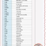
1 HP
745.7 watts (mechanical) or 746 watts (electrical)
Older equipment, machinery, motors
1 Watt
1 joule per second
Electrical appliances, modern equipment
1 Kilowatt (kW)
1,000 watts
Commercial HVAC systems
1 Megawatt (MW)
1,000,000 watts
Industrial facilities
Conversion Formula:
textWatts = HP × 746
HP = Watts ÷ 745.7
Practical Examples: HP to Watts Conversions
Horsepower
Watts
Kilowatts
Common Application
0.5 HP
373 W
0.373 kW
Residential AC units, small pumps
1 HP
746 W
0.746 kW
Compressor motors, medium capacity units
1.5 HP
1,119 W
1.119 kW
Commercial cooling systems
2 HP
1,492 W
1.492 kW
Industrial refrigeration
3 HP
2,238 W
2.238 kW
Large commercial systems
5 HP
3,730 W
3.730 kW
Heavy-duty industrial applications
Engineer’s Note: The difference between 745.7 W and 746 W is negligible in practical applications. Use 745.7 for mechanical conversions and 746 for electrical motors. This small variation rarely exceeds ±0.1% error in system calculations.
Current Conversion: Amperage and Electrical Load Calculations
Understanding Amps, Volts, and Power Factor
Amperage (AMPS) represents electrical current flow. Calculating amperage correctly is critical for:
Selecting proper circuit breaker sizes
Determining wire gauge requirements
Assessing electrical system capacity
Preventing overload conditions
The relationship between watts (W), volts (V), and amperes (A) depends on your electrical system configuration:
This is where many technicians make costly mistakes. kVA and kW are NOT the same thing:
kW (kilowatts) = Real power actually used by equipment
kVA (kilovolt-amperes) = Apparent power (total electrical capacity)
The relationship between them depends on power factor:
textkW = kVA × Power Factor (PF)
kVA = kW ÷ Power Factor (PF)
kVA to Amperage Conversion
Single-Phase System:
textAmps = (kVA × 1000) ÷ Volts
Three-Phase System:
textAmps = (kVA × 1000) ÷ (Volts × 1.732)
kVA Rating
System
Voltage
Amperage
1 kVA
Single Phase
240V
4.17 A
1.74 kVA
Single Phase
240V
7.25 A
1.391 kVA
Three Phase
240V (line-to-line)
3.35 A
1 kVA
Three Phase
415V (line-to-line)
1.4 A
Real Application Example: A refrigeration compressor is rated 1 kVA at 240V (single phase):
Amperage = (1 × 1000) ÷ 240 = 4.17 amps
If power factor = 0.8, then kW = 1 × 0.8 = 0.8 kW = 800 watts
Refrigeration Cooling Capacity Conversions
Understanding Cooling Tons in HVAC Systems
One of the most confusing measurements in HVAC is the ton of refrigeration (TR). This is NOT a weight measurement—it’s a cooling capacity unit defined historically as:
1 Ton of Refrigeration = 12,000 BTU/hour = 3.517 kW
This specific value comes from the heat required to melt one ton of ice in 24 hours, which became the standard refrigeration capacity unit.
Important: A metric tonne of refrigeration (often used in Europe) is slightly different:
1 Metric Tonne of Refrigeration ≈ 3.861 kW (10% larger)
1 Refrigeration Ton (US) = 3.517 kW
Always verify which standard your equipment uses before ordering or calculating capacity.
Resistance Conversion: Ohms, Kiloohms, Megaohms, and Gigaohms
Electrical Resistance Measurement Scale
Resistance measurements span enormous ranges in electrical systems. Understanding the conversion hierarchy is essential for proper diagnostics and troubleshooting:
Diagnostic Rule: Use megaohm scale (insulation resistance testers) for safety-critical motor testing. A healthy motor should show >100 MΩ insulation resistance.
Power Conversion Relationships: Comprehensive Reference Table
This consolidated table shows the relationships between all major electrical units in a single HVAC calculation context:
HP
Watts
kW
kVA (PF=0.8)
kVA (PF=0.9)
Refrigeration Tons
0.5
373
0.373
0.466
0.415
0.106
1
746
0.746
0.933
0.829
0.212
1.5
1,119
1.119
1.399
1.243
0.318
2
1,492
1.492
1.865
1.658
0.424
3
2,238
2.238
2.798
2.487
0.636
5
3,730
3.730
4.663
4.145
1.060
Real-World Application Scenarios
Scenario 1: Compressor Selection and Electrical Planning
You’re specifying a refrigeration compressor for a medium-sized cooling room. The equipment datasheet lists:
Rating: 1 HP motor
Available Supply: 240V, single-phase
Calculations Needed:
Convert to watts: 1 HP × 746 = 746 watts = 0.746 kW
Calculate amperage (assuming PF = 0.85):
Amps = 746 ÷ (240 × 0.85) = 746 ÷ 204 = 3.66 amps
Circuit breaker sizing (standard practice: 125% of running current):
Wire gauge selection (based on amperage and distance from panel):
For 3.66 amps over moderate distance → 10 AWG wire minimum
Decision: This 1 HP compressor is suitable for your 240V system with standard residential electrical configuration.
Scenario 2: Comparing International Equipment Specifications
You have two compressor options:
Option A (US manufacturer): 3 HP, R-134a, 1Ph 240V
Option B (European manufacturer): 2.2 kW, R-134a, 1Ph 240V
Which is more powerful?
Convert Option A to metric:
3 HP × 746 = 2,238 watts = 2.238 kW
Result: Option A (2.238 kW) is slightly more powerful than Option B (2.2 kW)—essentially equivalent performance.
Scenario 3: Cooling Capacity Planning
A facility requires cooling capacity assessment:
Current System: 2 Tons of refrigeration
Future Requirement: 10 kW cooling capacity
Are they compatible?
Convert 2 TR to kW:
2 TR × 3.517 = 7.034 kW
Answer: Your current system provides 7.034 kW, but you need 10 kW. You require approximately 0.85 additional tons (3 TR total) of refrigeration capacity.
Essential Conversion Formulas for Quick Reference
Power Conversions
text• Watts = HP × 746
• HP = Watts ÷ 745.7
• kW = Watts ÷ 1000
• kVA = kW ÷ Power Factor
ASHRAE (American Society of Heating, Refrigerating and Air-Conditioning Engineers): Establishes HVAC standards including measurement units
IEEE (Institute of Electrical and Electronics Engineers): Defines electrical conversion standards
IEC (International Electrotechnical Commission): Global standard for electrical units
NEMA (National Electrical Manufacturers Association): US motor and equipment standards
Regional Measurement Preferences
Region
Preferred Units
Voltage Standards
Frequency
United States
HP, Watts, Tons, 240V/480V
120V/240V (residential)
60 Hz
European Union
kW, Watts, Metric Tonnes, 380V/400V
230V/400V standard
50 Hz
Asia-Pacific
Mixed (HP and kW), 380V/415V
Varies by country
50 Hz typical
Middle East/Africa
Increasingly metric (kW), 380V/400V
230V/380V common
50 Hz
Professional Note: Always verify local electrical codes before installation. Equipment must comply with regional voltage standards and frequency requirements.
Conclusion: Mastery of Unit Conversions Ensures Project Success
Understanding electrical and refrigeration unit conversions is not merely academic—it’s practical knowledge that prevents costly mistakes, ensures safety, and optimizes system performance. Whether you’re selecting a compressor, calculating electrical loads, or diagnosing operational problems, these conversion formulas and reference tables will serve you reliably.
The key principles:
Know your source data (always convert from verified specifications)
Document your calculations (maintain audit trail of all conversions)
Apply safety factors (always round up for circuit breaker sizing)
Cross-reference conversions (verify using multiple methods when critical)
Maintain current reference materials (standards evolve; stay informed)
Mbsm.pro and Mbsmgroup recommend bookmarking this conversion guide and maintaining printed copies in your field toolkit. When precision matters—and in refrigeration and HVAC, it always does—having immediate access to accurate conversion data eliminates guesswork and prevents operational failures.
For specialized equipment specifications, technical datasheets, or installation support, refer to manufacturer documentation and consult with qualified HVAC professionals in your region.
About the Author’s Expertise
This comprehensive guide reflects years of practical HVAC and refrigeration experience. Mbsm.pro specializes in detailed technical documentation for refrigeration equipment, creating resources that bridge the gap between manufacturer specifications and field application. Our content serves HVAC professionals, refrigeration engineers, and technical students who demand accuracy and practical applicability.
KEY TAKEAWAYS
✓ 1 HP = 746 watts (fundamental conversion for all HVAC work) ✓ 1 Ton of Refrigeration = 3.517 kW (cooling capacity standard) ✓ kW ≠ kVA (always account for power factor in electrical calculations) ✓ Power Factor matters (typically 0.8-0.95 in HVAC equipment) ✓ Verify voltage and phase before every installation (240V single-phase vs. 380V three-phase) ✓ Use proper wire sizing (undersized wiring creates fire hazards) ✓ Document all conversions (maintain specifications for future reference)
Electrical unit conversion reference table: HP to watts, KVA to amps, tons refrigeration to kW mbsmpro
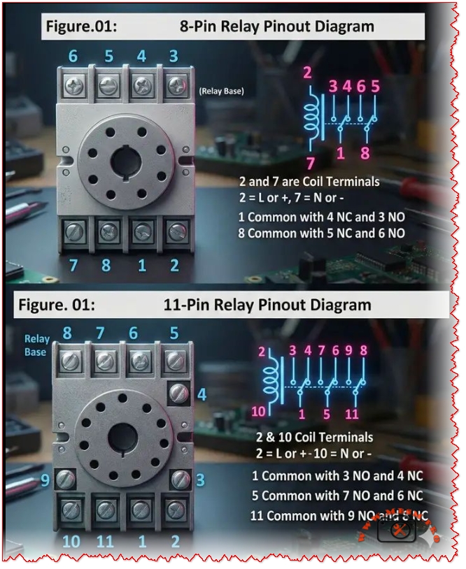
8‑pin and 11‑pin relay bases are common in control panels
Category: Global Electric
written by www.mbsmpro.com | January 30, 2026
Mbsmpro.com, Relay Base, 8‑Pin vs 11‑Pin, Pinout, Coil Terminals, COM, NO, NC, Wiring Guide, DPDT, 3PDT, Control Panel, HVAC
8‑pin and 11‑pin relay bases are common in control panels, but miswiring coil and contact terminals can burn a load or keep a circuit from switching. This guide explains each pin function, shows practical wiring logic for NO/NC contacts, and compares 8‑pin DPDT sockets with 11‑pin 3PDT sockets for automation work in HVAC retrofits today.
Excerpt (first 55 words): 8‑pin and 11‑pin relay bases are common in control panels, but miswiring coil and contact terminals can burn a load or keep a circuit from switching. This guide explains each pin function, shows practical wiring logic for NO/NC contacts, and compares 8‑pin DPDT sockets with 11‑pin 3PDT sockets for automation work in HVAC retrofits today.
Relay base pinouts
An 8‑pin “octal” relay base is typically used for a DPDT relay (two changeover contact sets), while an 11‑pin base is commonly used for a 3PDT relay (three changeover contact sets).
8‑pin relay base (DPDT) — pin functions
Pin
Function
2, 7
Coil (energize the relay)
1
COM for contact set #1
4
NC with COM=1
3
NO with COM=1
8
COM for contact set #2
5
NC with COM=8
6
NO with COM=8
Quick rule: when the coil is OFF, COM touches NC; when the coil is ON, COM switches to NO.
Scenario A: Holding (latching) circuit with an 8‑pin relay
A common use of an 8‑pin relay is a holding/latching circuit where one NO contact “seals in” the coil after a momentary START signal.
Copy-ready steps:
Feed the coil on pins 2 and 7, then use one NO contact (COM=1 to NO=3) as the holding path.
Scenario B: Interlocking with an 11‑pin relay
An 11‑pin relay’s three contact sets are often used to create electrical interlocking and holding logic (example: forward/reverse or lead/lag lockout) while keeping extra contacts for status/alarms.
Copy-ready steps:
Power the coil on pins 2 and 10, then assign one contact set for the hold path, one for interlock permissive, and one for feedback (COM/NC/NO groups shown in the table above).
Troubleshooting
If a relay “never pulls in,” confirm the coil pins first (8‑pin: 2 & 7; 11‑pin: 2 & 10) and verify the correct control voltage is actually reaching the coil.
If outputs look “reversed,” it’s usually because COM and NO/NC were swapped; one practical reference notes that pins 2 and 7 are coil pins on an 8‑pin relay and explains which pins behave as open vs closed contacts.
When base numbering is confusing, use a multimeter continuity test: find COM, then check which terminal is continuous with COM when the coil is off (NC) and when energized (NO).
Yoast SEO package
Focus keyphrase (≤191 chars): 8 pin relay base pinout and 11 pin relay base pinout wiring (coil, COM, NO, NC)
Related keyphrases to target (search intent):
8 pin relay socket wiring
octal relay base pinout
DPDT relay base terminals 2 7
11 pin relay socket pin diagram
3PDT relay base wiring
relay COM NO NC meaning
relay interlocking wiring diagram
relay holding (seal-in) circuit wiring
SEO title (Yoast): 8‑Pin vs 11‑Pin Relay Base Pinout (Coil, COM, NO, NC) | Mbsmpro
Meta description (Yoast): Learn the 8‑pin and 11‑pin relay base pinout fast: coil terminals, COM/NO/NC contacts, DPDT vs 3PDT differences, and wiring tips for holding and interlocking control circuits.
On-page SEO note: strong page titles improve click-through and relevance, so keep the main keyphrase near the start of the title and make it specific to the exact pinout problem being solved.