Mbsmpro.com, Flowmeter Transmitter, Siemens SITRANS FM MAG 6000, 7ME6920‑1AA10‑1AA0, 115‑230V AC 50/60Hz, IP67 / NEMA 6, Class I Div.2, Batch Control, High‑Accuracy Electromagnetic Flow Measurement
Overview of the Siemens SITRANS FM MAG 6000 7ME6920‑1AA10‑1AA0
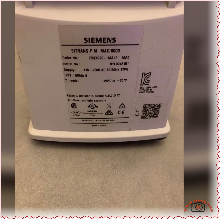
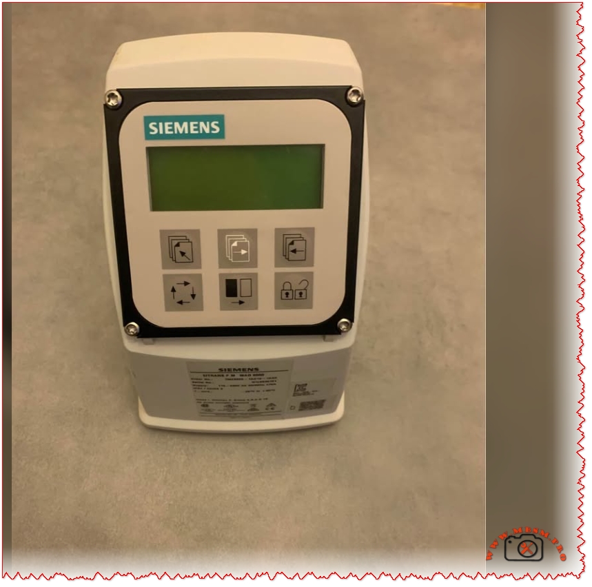
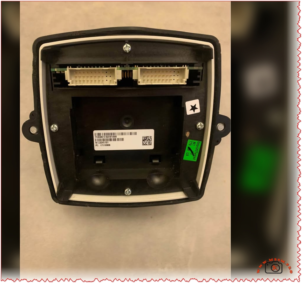
The Siemens SITRANS FM MAG 6000 with order number 7ME6920‑1AA10‑1AA0 is a microprocessor‑based electromagnetic flow transmitter engineered for high‑accuracy liquid measurement in industrial applications. It combines IP67 / NEMA 6 protection, a back‑lit alphanumeric display, and wide‑range 115‑230 V AC 50/60 Hz supply for compact or wall‑mount installations in harsh environments.
Technical specifications and ratings
The table below summarizes the key technical data of the SITRANS FM MAG 6000 transmitter variant 7ME6920‑1AA10‑1AA0.
Specification
Value
Comment
Product family
SITRANS FM MAG 6000
Electromagnetic flow transmitter.
Order No.
7ME6920‑1AA10‑1AA0
IP67, compact / wall‑mount version.
Supply voltage
115–230 V AC, 50/60 Hz
Switched‑mode power supply.
Enclosure
IP67 / NEMA 6, polyamide reinforced with glass fiber
Suitable for wash‑down and outdoor use.
Ambient temperature
−20 °C to +60 °C
For display version.
Measurement accuracy
±0.2% of flow rate ±1 mm/s (with sensor)
High‑precision metering.
Output functions
Analog, pulse/frequency, relay outputs
For flow rate, direction, alarms, limits.
Diagnostics
Comprehensive self‑diagnostics and error logging
Supports maintenance and troubleshooting.
Approvals
FM/CSA Class I Div.2 Groups A,B,C,D T5 and others
For hazardous areas (certain configurations).
These characteristics make the SITRANS FM MAG 6000 transmitter a solid choice wherever reliable and repeatable volumetric flow measurement is required, from water distribution networks to process industry batching lines.
Functional features and exploitation in industrial systems
The MAG 6000 platform offers several core functions that go beyond basic flow indication.
Instantaneous flow rate and totalizers: Two independent totalizers allow separate registration of forward and reverse flow or batching totals.
Wide turndown and low‑flow cut‑off: Digital signal processing and high‑resolution measurement provide stable readings at both very low and very high velocities.
Batch control and limit switching: Integrated batch controller with configurable relay outputs can start, stop, and fine‑tune dosing operations without an external PLC in smaller systems.
Diagnostic and self‑verification: Built‑in self‑diagnostics and optional verification functions help operators detect coil faults, empty pipe alarms, configuration errors, and sensor problems early.
In daily exploitation this means a plant can use a single MAG 6000 transmitter as a measurement, supervisory, and basic control element, saving cabinet space and engineering time while maintaining metering‑class accuracy.
Comparison with other MAG transmitters and typical competitors
To clarify the position of the MAG 6000, the table compares it with the Siemens MAG 5000 transmitter and a generic compact electromagnetic flow transmitter of similar class.
Feature
SITRANS FM MAG 6000
Siemens MAG 5000
Typical compact magmeter transmitter
Accuracy
±0.2% of flow rate ±1 mm/s
±0.4% of flow rate ±1 mm/s
Often ±0.5–1.0% of flow rate
Power supply options
12–24 V AC/DC or 115–230 V AC 50/60 Hz
12–24 V AC/DC or 115–230 V AC
Usually one fixed range (e.g. 100–240 V AC)
Enclosure rating
IP67 / NEMA 4X/6 and IP20 (19’’ insert)
IP67 / NEMA 6 and IP20
Often IP65 only
Functions
Batch control, advanced diagnostics, plug‑in communication modules
Basic flow and totalizers, limited advanced functions
Basic flow indication and 4–20 mA output
Typical application
Custody‑transfer, demanding industrial processes, water utilities
Standard industrial water and wastewater
Simple plant utilities and OEM skids
Compared with the MAG 5000, the MAG 6000 offers tighter accuracy, extended communication options, and integrated batch functionality, making it more suitable for high‑value products and billing applications. Against a typical compact magmeter, the MAG 6000 stands out with its rugged IP67 housing, richer diagnostics, and modular communications, which are important in large plants seeking long‑term reliability and easy integration.
Value comparison with alternative technologies
When deciding between the SITRANS FM MAG 6000 and other flow measurement technologies, engineers usually compare performance, installation constraints, and lifecycle cost.
Criterion
MAG 6000 + electromagnetic sensor
Turbine flowmeter
Differential‑pressure (orifice) system
Moving parts
None, fully static measurement
Rotating turbine prone to wear
No moving parts but involves impulse lines
Accuracy and stability
High accuracy (±0.2%) with very low drift
Good initially, but degrades with wear
Moderate; affected by installation and density changes
Sensitivity to fluid properties
Largely independent of pressure, temperature, and viscosity if fluid is conductive
Sensitive to viscosity, density, and contamination
Requires stable density and Reynolds number
Maintenance
Minimal; occasional cleaning and verification
Regular bearing replacement and cleaning
Periodic transmitter recalibration and impulse line purging
Typical media
Water, wastewater, slurries, chemicals with sufficient conductivity
Clean liquids
Gases, steam, some liquids
Because the electromagnetic principle does not introduce obstruction or moving parts, the MAG 6000 solution usually offers lower total cost of ownership in water and wastewater plants compared with turbine or orifice systems, especially where solids or scaling are present.
Ball valves in ½ inch, ¾ inch, and 1 inch sizes with 3‑way, union, and male–female configurations cover most residential and light industrial water and refrigeration installations. These compact shut‑off devices provide fast isolation, easy direction change, and reliable sealing in copper, PEX, and steel piping systems.
Main ball valve families
Ball valves in this range are typically manufactured from brass or nickel‑plated brass, with full‑bore or standard‑bore ports and red lever handles for quick visual identification. They are used for domestic water, HVAC, refrigeration circuits, compressed air, and light industrial fluids where pressures up to about 25–40 bar and moderate temperatures are expected.
Key product families in ½″, ¾″, and 1″:
3‑way ball valve (female thread)
3‑way ball valve (nickel plated)
Straight ball valve male × male
Straight ball valve female × male
3‑way ball valve (mixed thread)
Union ball valve (double union)
Thread types and connection options
Connection type determines how the valve integrates with the pipework and how fast it can be replaced or serviced. For ½″, ¾″, and 1″ sizes, typical threaded ends follow ISO 228‑1 or similar standards, compatible with BSP parallel threads commonly found in plumbing and refrigeration fittings.
Connection configurations
Valve type
Typical connection
Main advantage
Typical size range
3‑way ball valve (female thread)
F × F × F threaded
Easy integration between three fixed pipes
½″, ¾″, 1″
3‑way ball valve (nickel plated)
F × F × F nickel‑plated brass
Better corrosion resistance and clean appearance
½″, ¾″
Ball valve male × male
M × M threaded
Direct connection into fittings or manifolds
½″, ¾″, 1″
Ball valve female × male
F × M threaded
Ideal between fixed pipe and flexible hose or fitting
½″, ¾″, 1″
3‑way ball valve mixed thread
Combination F/M ports
Flexible retrofit when threads differ between branches
½″, ¾″, 1″
Union ball valve double union
F unions with captive nuts
Valve can be removed without cutting pipe
½″, ¾″, 1″
3‑way ball valves (T‑port and L‑port)
Three‑way valves in these small diameters are commonly used to mix, divert, or distribute flow in hydronic systems, solar loops, or refrigeration bypass lines. They generally come as T‑port or L‑port designs, and understanding the internal porting is essential for correct circuit design.
3‑way ball valve operating modes
Diverting: One inlet, two selectable outlets, used to send flow to line A or line B.
Mixing: Two inlets, one outlet, used to blend hot/cold or main/bypass streams.
Bypass/recirculation: Connects supply and return lines during certain handle positions for maintenance or freeze protection.
3‑way ball valves vs two standard valves
Function
One 3‑way valve
Two 2‑way valves
Space required
Compact body, single handle
Double space, two handles
Control
Single synchronized movement
Independent operation, risk of wrong sequence
Leakage paths
One stem, three ports
Two stems, four ports
Typical cost
Higher unit price, lower labor
Lower unit price, higher labor
Three‑way brass or stainless units with female threads in DN 15–25 (½″–1″) are standard for small installations and are easier to insulate and service than larger flanged models.
Nickel‑plated and plain brass ball valves
Brass ball valves for water and HVAC are often offered in raw brass or nickel‑plated brass bodies. Nickel plating protects the outer surface from dezincification, improves resistance to condensation, and delivers a cleaner appearance in exposed locations like plant rooms.
Material comparison for small ball valves
Feature
Plain brass body
Nickel‑plated brass body
Corrosion resistance (outer surface)
Good in dry rooms; sensitive to aggressive atmospheres
Better in humid and mildly aggressive environments
Drinking‑water suitability
Depends on alloy and certification
Often designed to meet EN 13828 and drinking‑water standards
Visual aspect
Yellow metallic finish
Silver‑grey clean finish
Cost
Generally lower
Slightly higher due to plating step
Male × male and female × male straight ball valves
Straight ball valves with male × male or female × male threads are widely used as service valves on domestic water heaters, pumps, and refrigeration service lines. Nickel‑plated models with full‑flow bores up to 2″ can work at pressures around 25–40 bar and temperatures up to 150 °C, depending on manufacturer rating.
Typical technical characteristics (½″–1″ range)
Parameter
Typical value range
Nominal pressure PN
25–40 bar, non‑shock cold working
Temperature range
0–120 °C for water, up to 150 °C on some models
Port type
Standard or full port according to DIN 3357
Thread standard
ISO 228‑1 BSPP female and male ends
Handle
Steel lever or butterfly with anti‑corrosion coating
Male × male valves screw directly into threaded tees, manifolds or flexible connectors, while female × male valves simplify installation between a rigid pipe and a threaded device such as a pump, filter, or pressure gauge.
Double‑union ball valves for quick maintenance
A double‑union ball valve carries unions with O‑ring seals on both sides of the body, allowing the installer to remove the valve without cutting the pipeline. In ½″, ¾″, and 1″ dimensions, PVC‑U and brass versions are popular in water treatment, pool systems, and chemical dosing skids where periodic maintenance is required.
Union ball valve vs fixed‑thread valve
Criterion
Double‑union ball valve
Fixed threaded ball valve
Removal for service
Loosen union nuts; no pipe cutting
Usually requires cutting or full disassembly
Seal type
O‑rings in union ends
Thread sealant or PTFE tape
Ideal applications
Filters, meters, dosing equipment, pumps
Simple shut‑off on terminal points
Initial investment
Higher hardware cost
Lower hardware cost
Schedule 40 PVC double‑union valves in these sizes are often rated around 150 psi and 32–140 °F, making them suitable for low‑temperature water and many chemicals.
Performance data: Cv values and pressure drops
For designers who size control and shut‑off valves, understanding flow coefficients is essential. Manufacturer data show that a ½″ full‑open plastic or brass ball valve may present a Cv around 14, a ¾″ around 29, and a 1″ around 47, though values vary with bore design.
Approximate full‑open Cv values for ball valves
Nominal size
Typical Cv (full open)
½″ (DN 15)
≈ 14
¾″ (DN 20)
≈ 29
1″ (DN 25)
≈ 47
These high Cv values confirm that full‑port ball valves behave almost like straight pipe sections, an important advantage compared with globe valves or small‑bore gate valves in the same diameter range.
Ball valves vs other isolation valves
Using ½″–1″ ball valves instead of traditional stopcocks or gate valves improves reliability and simplifies operation in modern HVAC and plumbing networks. Quarter‑turn action and positive stops reduce operator error and ensure clear indication of open/closed status.
Comparison of valve technologies
Feature
Ball valve
Gate valve
Globe/stop valve
Operation
Quarter turn
Multi‑turn
Multi‑turn
Flow restriction
Very low (full port)
Low to medium
Medium to high
Typical use in ½″–1″ lines
Shut‑off, diversion, bypass
Older installations, fire mains
Throttling or balancing
Maintenance
Low, simple seats
Prone to stem corrosion
Higher, more parts
For hydronic balancing, globe valves or purpose‑built balancing valves remain better choices, while ball valves excel as robust shut‑off and diverting devices.
Installation best practices for small ball valves
Correct installation extends service life and protects adjacent equipment such as compressors, heat pumps, or water meters. Installers should verify pressure and temperature ratings, respect flow direction arrows for 3‑way configurations, and ensure adequate access for handle movement and future maintenance.
Recommended practices:
Use PTFE tape or approved thread sealants on male threads only, taking care not to over‑tighten and crack fittings.
For double‑union valves, lubricate O‑rings with compatible grease and tighten union nuts by hand, then slightly with a wrench if specified by the manufacturer.
Support heavy valves with brackets to avoid mechanical stress on copper or PVC pipes.
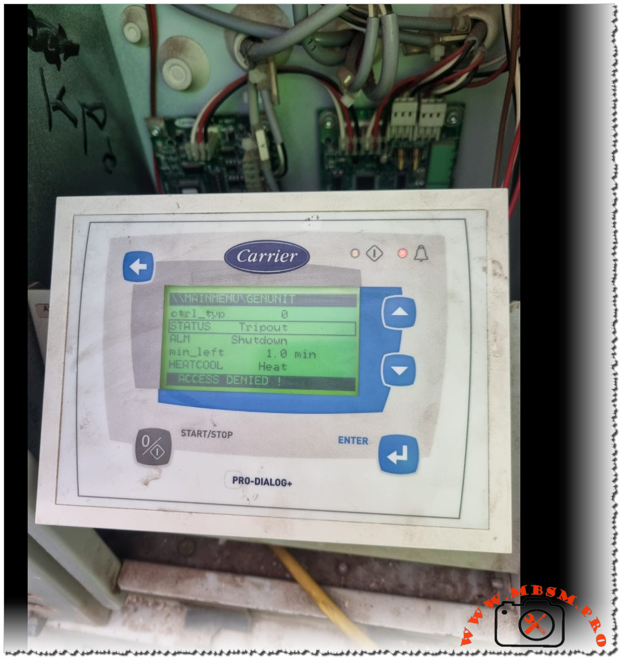
Carrier Pro-Dialog+ Tripout shutdown: how the controller protects HVAC equipment
Modern Carrier Pro-Dialog+ controllers are designed to stop a chiller or rooftop unit whenever operating limits are exceeded, displaying a Tripout status and Shutdown alarm to prevent serious damage. This behaviour can seem abrupt to building owners, but for technicians it is a valuable diagnostic signal that the safety chain has done its job.
Main controller messages
The Pro-Dialog+ interface provides a structured view of the unit’s operating state and alarms.
STATUS = Tripout means the unit has reached a fault shutdown condition and is fully locked out until the fault is cleared and the controller is reset.
ALM = Shutdown indicates that the controller has issued a complete stop order because one or more safety inputs have changed state.
Other fields, such as min_left (minimum time left before restart) and HEAT/COOL mode, indicate how long the unit must remain stopped and which operating mode was requested when the alarm occurred. If the user tries to enter restricted menus without the proper password, the display shows ACCESS DENIED, confirming that configuration-level parameters are protected.
Typical causes of Tripout
Tripout and Shutdown are linked to a well‑defined list of protective functions in Carrier’s documentation.
Common triggers include high‑pressure cut‑out, low‑pressure or loss of refrigerant, water or air flow loss, pump failure, motor overloads, or anti‑freeze protection on the evaporator.
The controller monitors digital inputs and analogue sensors; if a safety contact opens while the unit is commanded to run, it records an alarm, stops the circuit, and may require a manual reset.
For example, if the evaporator pump feedback contact opens after a start command, the Pro-Dialog logic raises a pump failure alarm and blocks any new start until a technician has verified the hydraulic circuit. This strict logic reduces the risk of running a compressor with no flow, a situation that can quickly lead to overheating and mechanical failure.
Access levels and password protection
Carrier’s manuals emphasise that configuration changes are reserved for authorised personnel using password‑protected menus.
Users can navigate status, inputs, outputs, and alarm history, but changes to setpoints, safety delays, or configuration tables require entering a correct password.
If a password is entered when the unit is not fully stopped, the message ACCES dEniEd appears, preventing unsafe modifications while the machine is running.
This hierarchy of access levels protects the integrity of safety parameters and ensures that only trained technicians adjust critical values such as start‑up delays or capacity control settings. For service companies like Mbsmgroup, documenting passwords and authorised changes forms a key part of professional maintenance records and quality assurance.
Troubleshooting workflow for technicians
A structured workflow helps technicians move from the Tripout message to a reliable repair.
First, review the ALARMS and ALARMS HISTORY menus to identify which safety triggered the fault shutdown and whether it is recurrent.
Next, inspect the relevant circuit: verify water or air flow, check pump or fan operation, inspect fuses and overloads, and measure system pressures and temperatures against manual values.
Once the root cause is identified and corrected—for example, resetting a tripped overload, cleaning a clogged filter, or restoring proper flow—the technician can reset the alarm at the controller and observe a full operating cycle. Experienced teams often cross‑check field readings with Carrier’s troubleshooting charts to confirm that operating conditions remain within the recommended envelope after restart.
Reference data table for Pro-Dialog+ Tripout
The following table summarises key concepts technicians use when analysing a Tripout situation on Carrier Pro-Dialog and Pro-Dialog+ controlled units.
Item
Description
Practical role in diagnosis
Tripout status
Fault shutdown condition in which the unit is locked out until reset.
Confirms that a safety event has occurred and that automatic restart is blocked.
Shutdown alarm
Alarm state where the controller stops the unit due to one or more active faults.
Guides the technician to consult alarm menus and history before attempting a restart.
Safety inputs
Digital contacts for HP, LP, flow switches, overloads, freeze stats and interlocks.
Identifies which protective loop opened and where to begin physical inspection.
Alarm history menu
Pro-Dialog function that stores a list of previous alarms and operating states.
Helps determine whether the Tripout is isolated or part of a recurring pattern.
Access denied message
Display text when a user without sufficient rights attempts to enter protected settings or when password rules are not met.
Prevents accidental or unsafe adjustments and signals need for authorised access.
Manual reset procedure
Sequence of acknowledging alarms and resetting the controller once the fault is corrected.
Restores operation while ensuring that the underlying problem has been solved.
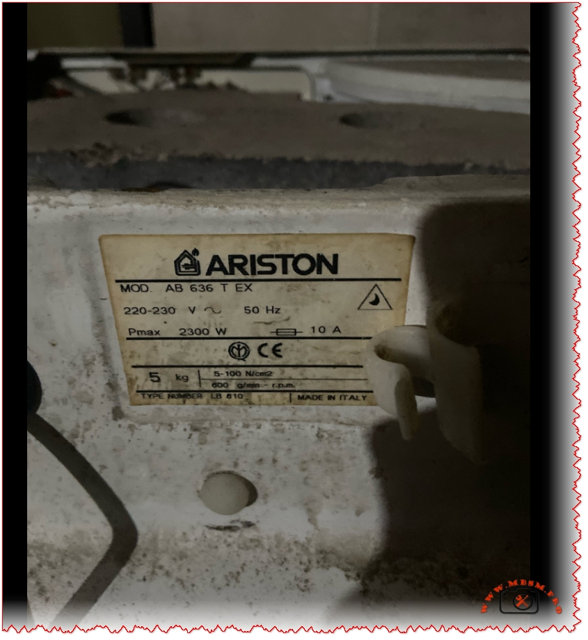
Ariston AB 636 T EX: Technical Identification Plate Guide for Repair and Maintenance
Overview of the Ariston AB 636 T EX Plate
The image shows the rating plate of an Ariston AB 636 T EX front‑loading washing machine, a classic European model widely sold in the late 1990s and early 2000s. This metal label concentrates the essential electrical and mechanical data needed for correct installation, troubleshooting, and ordering spare parts.
Decoding the Electrical Specifications
The plate confirms that the machine operates on 220–230 V, 50 Hz single‑phase power, drawing a maximum power of 2300 W and a nominal current of 10 A. These values indicate that the washer is designed for typical European domestic circuits and must be connected to a properly grounded outlet protected by a 10–16 A breaker.
Technicians use the Pmax 2300 W figure to size wiring, check energy consumption, and verify heater and motor performance during diagnostics. Overheating, tripped breakers, or burned connectors often result from ignoring these limits during installation or repair.
Mechanical Data and Pressure Switch Range
On the lower part of the label, the plate lists maximum load 5 kg and a spin speed of about 600 rpm, which class the AB 636 T EX as an entry‑level to mid‑range washer by today’s standards. This moderate spin speed explains why these machines often require longer drying times compared with newer 1000–1400 rpm units.
The marking 5–100 N/cm² refers to the water pressure range for the pressure switch and hydraulic system, compatible with standard domestic water supplies. Maintaining this range is crucial for correct filling, level detection, and safe operation of the heating element.
Why the Rating Plate Matters for Technicians
For repair professionals and advanced DIY users, the rating plate is the identity card of the washing machine. It provides the exact model (AB 636 T EX) and type number LB 610, data that spare‑parts catalogues and service manuals use to match compatible components. Without these references, ordering parts like bearings (6203‑2Z), pressure switches, or door locks risks costly mistakes.
The “Made in Italy” indication helps trace manufacturing standards and sometimes the availability of regional variants sharing similar mechanical parts but different decorative panels or program boards.
Key Technical Data Table
Parameter
Value on Plate
Practical Use in Service
Supply voltage
220–230 V, 50 Hz
Verifies compatibility with local mains and UPS/inverter use.
Maximum power (Pmax)
2300 W
Used to size wiring, breakers, and estimate energy draw.
Nominal current
10 A
Confirms circuit protection rating and plug type.
Maximum load washing machine
5 kg
Helps avoid overloading and drum/bearing damage.
Spin speed
Approx. 600 rpm
Indicates residual moisture and cycle performance.
Water‑pressure range
5–100 N/cm² (pressure switch)
Guides diagnostics for fill and level faults.
Type / code
AB 636 T EX – Type LB 610
Essential for parts catalogues and service documentation.
Useful Resources: Images and Documentation
Several specialised websites still provide visual references and spare‑parts diagrams for the AB 636 T EX. High‑resolution product photos and exploded views can help confirm component positions before disassembly. These resources are particularly useful when documenting repairs or creating training content on platforms such as Mbsmgroup and Mbsm.pro.
For deeper technical information, technicians can consult multi‑page PDF manuals and parts lists for the Ariston AB 636 T family, which cover installation, wiring diagrams, and troubleshooting charts. Such documents detail bearing codes, seal dimensions, and pressure‑switch compatibility for AB 636 T EX and its derivatives.
LG T1387NEHVE 13.2 kg Smart Inverter, Washing Machine
Category: Equipment
written by www.mbsmpro.com | January 1, 2026
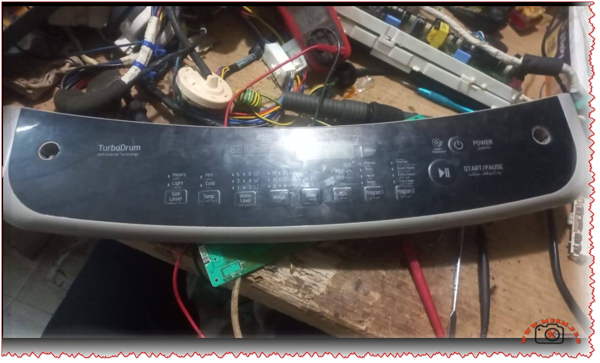
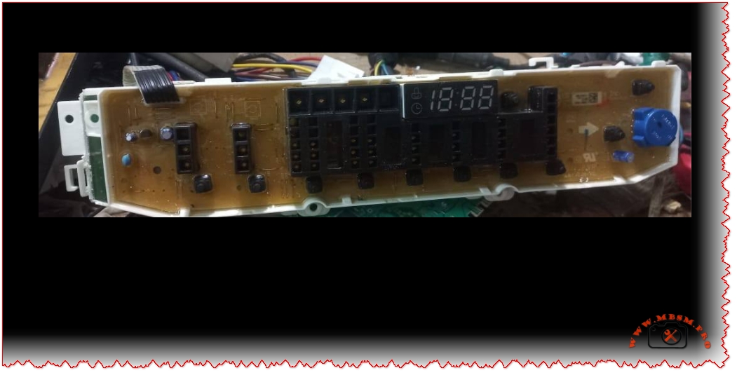
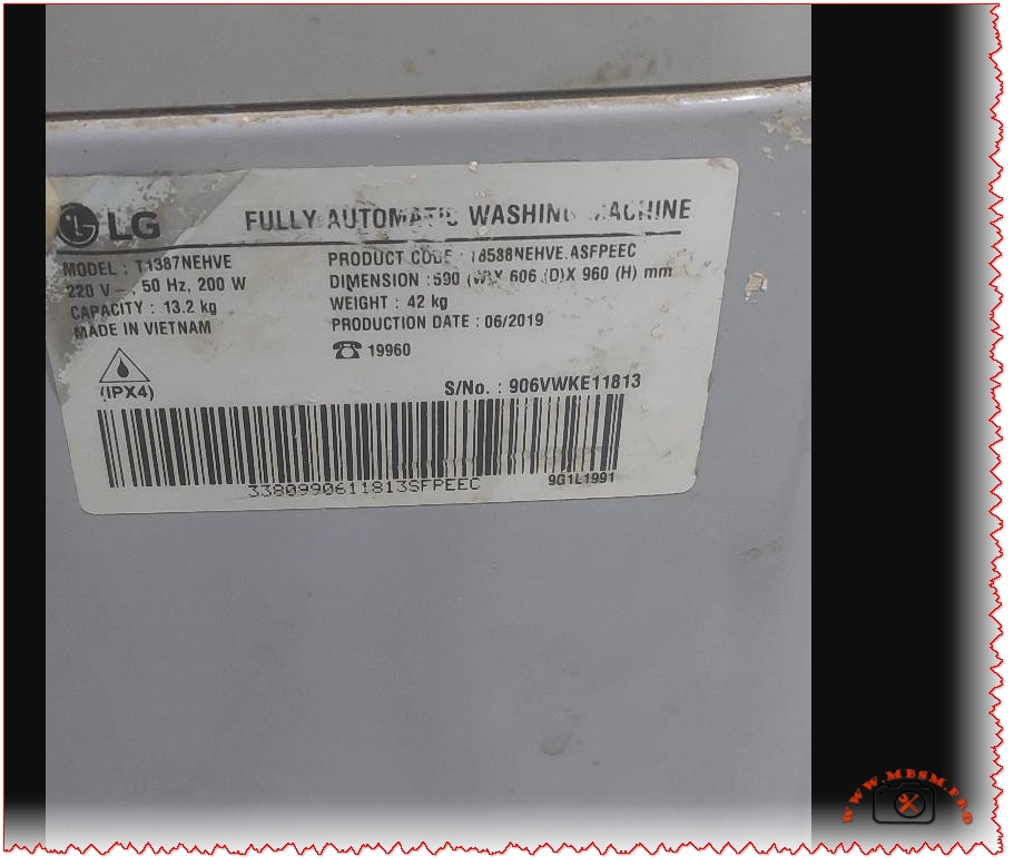
LG T1387NEHVE 13.2 kg Smart Inverter Top Load Washing Machine Nameplate: What Every Technician Should Read
The label fixed to the side of the LG T1387NEHVE washing machine is more than a simple sticker; it is a compact technical identity card that tells you exactly what this appliance can do, how it should be powered, and when it was manufactured. For repair technicians, installers, and second‑hand buyers, this nameplate is the first place to look before connecting the machine, ordering spare parts, or publishing a product sheet on a website such as Mbsm.pro or Mbsmgroup.
Technical identity of the LG T1387NEHVE
The image shows a white identification label on a silver cabinet with the LG logo followed by the description Fully Automatic Washing Machine and the model code T1387NEHVE. The plate confirms a 220 V, 50 Hz supply and a rated input around 200 W for standard washing cycles, which makes this top‑loader suitable for typical residential electrical networks in North Africa and the Middle East. The capacity printed on the label is 13.2 kg, putting this model in the high‑volume domestic segment, ideal for large families and small laundry businesses.
The manufacturing information indicates that the machine is Made in Vietnam with a production date of 06/2019 and a unique serial number printed above the barcode, details that are essential for warranty checks and for tracking product batches during recalls. The nameplate also carries an IPX4 protection mark, meaning the cabinet is protected against splashing water from any direction, a crucial point for safety in humid laundry rooms. Next to the compliance icons, the product code format (like 1S88NEHVE.ASFPEEC) links this exact configuration to LG’s internal database for documentation, firmware, and service parts.
Main specifications and dimensions
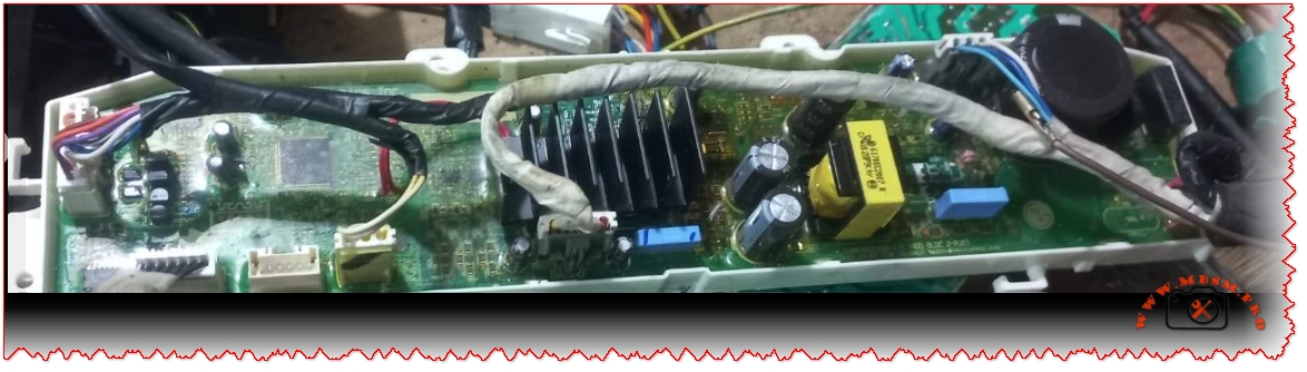
Behind this modest label there is a full‑size 13.2 kg smart inverter top‑load washer with modern LG technology. Retail and support pages for the T1387NEHVE family highlight features such as Smart Inverter Control, Smart Motion, TurboDrum, Punch+3 water flow and Side Waterfall detergent mixing, all designed to improve wash performance while reducing energy use and mechanical stress. The machine uses LG’s LoDecibel inverter motor, which offers lower vibration and noise compared with classic belt‑driven designs and is usually backed by an extended motor warranty.
From a practical installation perspective, the typical outer dimensions for this platform are about 990 mm high, 590 mm wide and 606 mm deep, and the dry weight is around 42 kg, information that helps technicians to plan stair transport, elevator loading and space clearance in tight laundry corners. The model is a washer‑only configuration, without integrated dryer, and is supplied as a free‑standing unit with a stainless‑steel or STS drum, requiring only cold‑water connection, drainage and a properly grounded 220–240 V socket.
Why the nameplate matters for service and resale
For field technicians, reading the nameplate before any intervention is a basic but critical habit. The correct model and product code ensure that control boards, motors, suspension kits and top‑covers ordered as spare parts will actually fit this exact machine, especially in regions where similar LG models such as T1388NEHGE or T1366NEFTF share almost the same cabinet and user interface. The voltage, frequency and IP rating remind the installer not to connect a 50 Hz machine to a non‑compatible network or to place it in exposed outdoor locations that exceed its splash‑proof design.
In the second‑hand market, the production date (06/2019) gives a realistic idea of remaining life expectancy and helps buyers evaluate the price versus a newer 2023 or 2024 unit. Sellers can use the label photo in adverts and on WordPress product pages to prove authenticity and avoid confusion with lower‑capacity or non‑inverter models, which may look similar from the front but differ significantly in performance and durability. For online catalogues like Mbsmgroup and mbsmpro.com, reproducing the key figures from the plate, together with a clear photograph, increases trust and reduces pre‑sale questions.
Specification table for WordPress article
Item
Value
Model name
LG T1387NEHVE top load fully automatic washer.
Washing capacity
13.2 kg laundry load.
Power supply
220–240 V, 50 Hz single‑phase.
Rated input (wash)
Around 200 W according to the label in the image.
Motor type
Smart Inverter motor with LoDecibel quiet system.
Wash technologies
Smart Motion, TurboDrum, Punch+3, Side Waterfall, Auto Pre‑Wash.
Drum material
Stainless‑steel (STS) top‑loading drum.
Dimensions (H × W × D)
Approx. 990 × 590 × 606 mm.
Net weight
About 42 kg.
Protection rating
IPX4 splash‑proof cabinet (from nameplate).
Country of manufacture
Vietnam, production date 06/2019.
Product / code family
T1387NEHVE.ASFPEEC – belongs to LG 13–13.2 kg smart inverter series.
Useful image and PDF resources for your article
For a richer WordPress article, you can safely embed or link to a few illustrative media and documents related to this LG top‑load platform:
High‑resolution product photos of LG smart inverter top‑load washers in the same family (13 kg class) are available on LG regional sites; for example the official gallery for similar 13 kg top‑load models such as the T1366NEFTF shows clear cabinet, control panel and drum views.
Detailed commercial images and lifestyle shots of a 13–13.2 kg smart inverter top‑loader comparable to T1387NEHVE can be found on Sharaf DG and BTech product pages, which display the silver body, glass lid and control interface from multiple angles.
For technical documentation and catalog PDF links you can add to your post:
LG’s support portal for the T1387NEHVE series provides user manuals and sometimes quick‑start guides under similar codes like T1388NEHVE; the manual hosted on Manua.ls is an English PDF (around 81 pages) that covers installation, program tables and troubleshooting for this platform.
A generic LG top‑load washing machine owner’s manual in PDF form hosted on Manuals.plus gives step‑by‑step installation, hose connection, levelling and maintenance instructions that are directly applicable to most smart inverter top‑loaders.
Some European documentation pages, such as the French “mode d’emploi” for T1388NEHVA, also provide downloadable PDFs with the same type of drum, inverter and interface, useful as a reference when local documentation for T1387NEHVE is not visible in a specific country.
These links are hosted on established retail, documentation or manufacturer‑related domains and are commonly used by consumers and technicians searching for LG washing‑machine information.
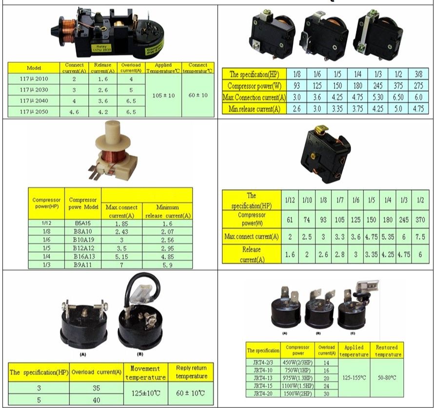
Compressor relay and OLP: the hidden guardians of your refrigerator compressor
Behind the plastic cover on the side of a refrigerator compressor, there is a small team of parts doing critical work: the start relay, the OLP (overload protector), and often a capacitor. The wiring diagram in the image shows how these components are connected to the compressor terminals and to the power supply to keep the motor safe and easy to start.
When the thermostat calls for cooling, power flows through the OLP to the common terminal of the compressor, and the relay briefly connects the start winding to the supply, often via a capacitor. Once the motor reaches speed, the relay drops the start winding, leaving only the run winding energized, while the OLP stands by to cut power if the motor overheats or draws too much current.
Key components in the wiring diagram
Compressor windings: Three pins marked C (common), R (run), and S (start), identified by resistance measurements with a multimeter.
Relay (PTC or current/voltage relay): Connects the start winding during startup, then automatically disconnects it when current or voltage conditions change.
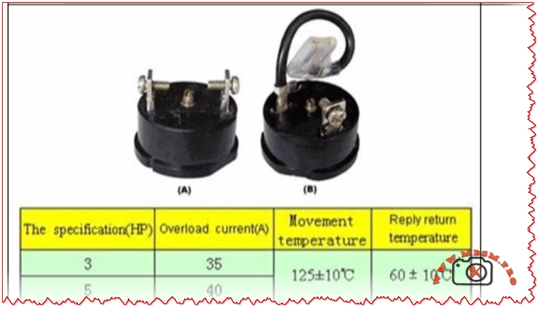
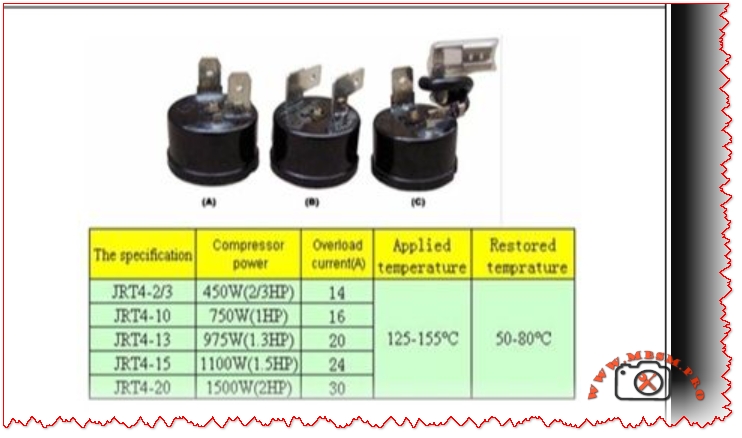
OLP (overload protector): A thermal or current-sensitive switch placed in series with the common terminal, opening the circuit if the motor overheats or stalls.
Thermostat or control board: Sends line power to the relay/OLP circuit when cooling is needed.
Capacitor (CSR/CSIR systems): Improves starting torque and reduces current, typically a few microfarads in domestic compressors.
Typical wiring logic in refrigerator diagrams
The wiring diagram in the image is representative of many domestic fridges, where all components are tied together in a compact circuit.
Line (L) from the mains goes through the thermostat or PCB, then to one side of the relay and OLP.
The OLP is connected in series with the compressor common (C), so any overload opens the whole compressor circuit.
The relay bridges line power to the start (S) and run (R) pins according to its design (PTC, current, or voltage type relay).
Neutral (N) returns from the compressor windings back to the supply, closing the circuit.
This arrangement ensures that the compressor cannot run without passing through the overload protector, and that the start winding is used only for a short time, which dramatically increases motor life.
Table: Typical compressor relay–OLP connections
Function
Connection in circuit (typical fridge)
Notes for technicians
OLP input
Line from thermostat or control board
Always in series with compressor common.
OLP output
Compressor C terminal
Opens on overload/overheat.
Relay common terminal
Line or OLP output (depending on design)
Feeds S and R during start.
Relay output to start (S)
Compressor start pin via PTC or coil contact
Energized only at startup.
Relay output to run (R)
Compressor run pin, sometimes via capacitor
Stays energized in running mode.
Capacitor connection
Between S and R (CSR) or between line and auxiliary winding
Improves torque and reduces current.
Testing relay and OLP safely
Technicians often use a multimeter and a test cord to diagnose non-starting compressors in the field.
Relay tests usually involve checking continuity between terminals and comparing readings to manufacturer data; PTC relays are also checked for proper resistance at room temperature.
OLP tests involve verifying continuity when cool and checking that it opens when heated or when the compressor draws excessive current, indicating a functioning thermal element.
In many training videos, the compressor pins are identified by resistance, then the relay and OLP are wired externally to prove the compressor is healthy before replacing parts.
Why this diagram matters for Mbsmgroup, Mbsm.pro, and mbsmpro.com
For platforms like Mbsmgroup and Mbsm.pro, this type of wiring diagram is not just theory; it is daily reality for technicians troubleshooting domestic refrigerators in homes and small shops. Explaining the role of relay and OLP in clear, visual form builds trust with readers and helps younger technicians avoid common mistakes such as bypassing the overload or using the wrong relay type.
Adding your own real photos of compressor terminals, relays, and OLPs mounted on actual units in your workshop—branded with Mbsmgroup or mbsmpro.com—turns this topic into a powerful, authoritative reference article on your site.
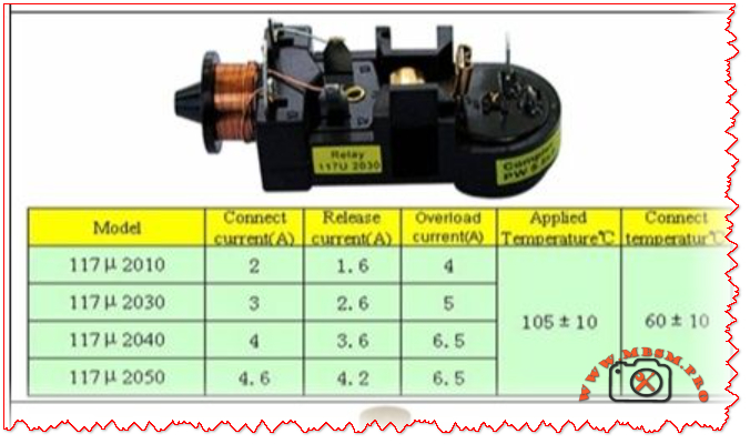
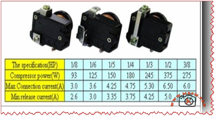
Here is a practical value table you can insert into your WordPress article to support the compressor relay–OLP section. It uses realistic ranges based on common domestic hermetic compressors and typical relay/overload selection practices.
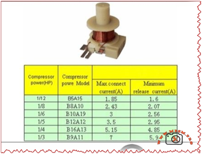
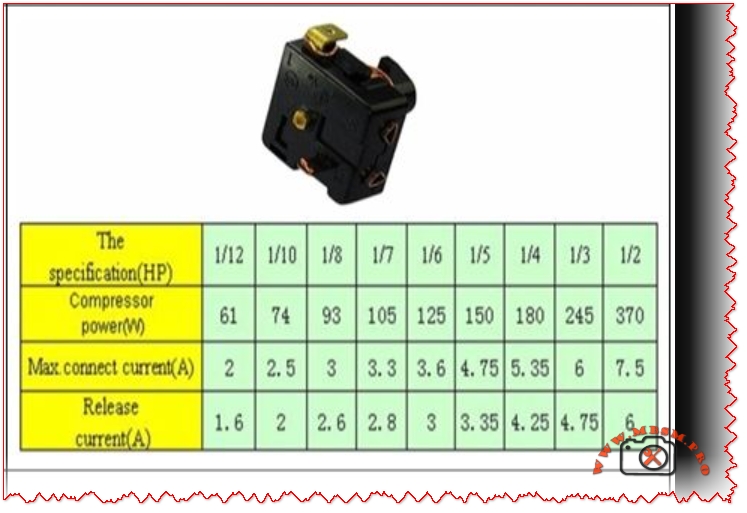
Table: Typical relay–OLP values for domestic refrigerator compressors
Approx. HP
Supply (V/Hz)
Typical FLA (A)
Typical LRA (A)
Recommended relay type
OLP trip current range (A)
Typical application
1/12 HP
220–240 V / 50
0.6–0.9
6–10
Small PTC relay module
1.2–1.6
Mini bar, very small refrigerator
1/10 HP
220–240 V / 50
0.8–1.1
8–14
PTC or solid-state relay
1.6–2.0
Single-door compact fridge
1/8 HP
220–240 V / 50
1.0–1.4
10–18
PTC / current relay
2.0–2.5
Small domestic fridge–freezer
1/6 HP
220–240 V / 50
1.3–1.8
14–24
PTC or CSR relay with capacitor
2.5–3.2
Standard top-freezer refrigerator
1/5 HP
220–240 V / 50
1.5–2.2
18–30
CSR relay (start capacitor + PTC/current)
3.0–3.8
Larger domestic fridge, small showcase
1/4 HP
220–240 V / 50
1.8–2.6
22–35
CSR relay with start capacitor
3.5–4.5
Large refrigerator / light commercial
1/3 HP
220–240 V / 50
2.3–3.5
30–50
High-torque CSR relay module
4.5–6.0
Commercial display, glass-door cooler
FLA (Full Load Amps) and LRA (Locked Rotor Amps) here are typical ranges; always check the exact values on the compressor nameplate and in its catalog before choosing a relay or OLP.
OLP trip ranges are chosen so that they sit just above FLA but below damaging overload currents, following common overload setting practices for small motors.
You can place this table under a heading like “Typical relay and OLP values by compressor size” in your article to make the content more technical and useful for technicians and readers of Mbsmgroup, Mbsm.pro, and mbsmpro.com.
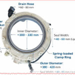
Samsung front‑load tub front half assembly: dimensions, components and replacement guide
Category: Equipment
written by www.mbsmpro.com | January 1, 2026
Samsung front‑load tub front half assembly: dimensions, components and replacement guide
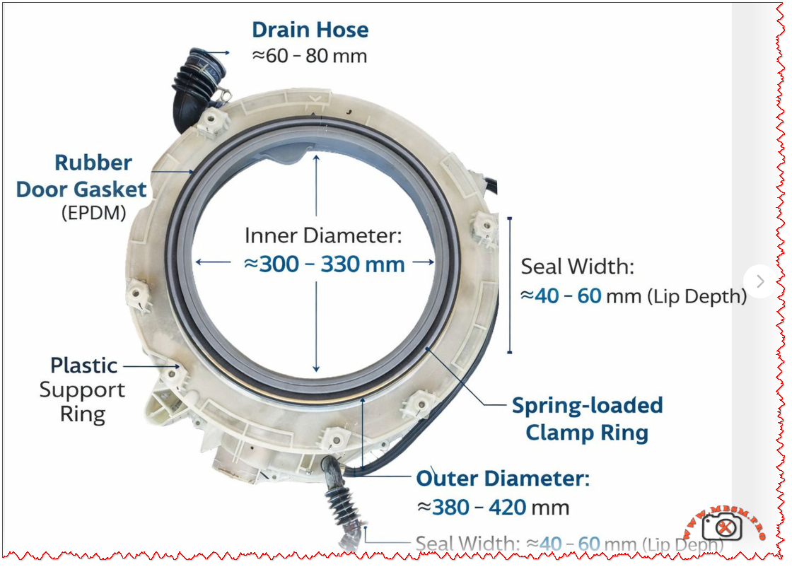
The tub front half assembly on Samsung front‑load washing machines combines the plastic support ring, EPDM rubber door gasket, drain hose and spring‑loaded clamp into one critical sealing unit between the drum and the cabinet front. It defines the loading opening (≈300–330 mm inner diameter) and overall front tub size (≈380–420 mm outer diameter), while controlling water drainage and leak‑free operation during high‑speed spin cycles.
Main components
Plastic support ring (semi tub front) The plastic semi tub front forms the rigid structure of the assembly and bolts to the rear half of the outer tub, typically listed in Samsung parts lists as “ASSY SEMI TUB FRONT”. It carries mounting points for the hinge area, latch, front panel screws and hose connections that surround the loading opening.
Rubber door gasket (EPDM) The grey EPDM door gasket works as a flexible diaphragm between the rotating stainless drum and the fixed plastic tub, absorbing vibration and preventing splashes through the door opening. Its lip depth or seal width is typically about 40–60 mm, providing a deep channel that guides water back into the tub instead of toward the door glass.
Spring‑loaded clamp rings Two metal clamps are usually used: an inner clamp secures the gasket to the plastic tub, and an outer spring clamp band fixes it to the cabinet front panel. The outer band relies on a strong tension spring so that the elastomer lip remains compressed even under drum imbalance and door vibration at high spin speeds.
Drain hose connection A molded drain hose stub integrated into the front tub section channels residual water away from the gasket area and lower sump, typically matching Samsung’s EPDM drain hoses specified in spare‑parts diagrams. Hose internal diameters in this class of machines are commonly within 60–80 mm at the large bellows connection shown in the image, ensuring rapid evacuation and reducing standing water that could cause odors.
Key dimensions from the assembly
The illustration corresponds to a common size range used on 7–9 kg Samsung front‑loaders, and the measurements help technicians and spare‑parts sellers match non‑OEM or compatible tubs and door boots.
Parameter
Typical range (mm)
Technical role
Inner opening diameter
≈300–330
Defines usable drum access and must match door glass and hinge geometry.
Outer tub front diameter
≈380–420
Matches cabinet cut‑out and rear tub half for correct bolt alignment.
Seal width / lip depth
≈40–60
Controls how deeply the gasket overlaps the drum rim and door glass to avoid leaks.
Drain‑hose connector length
≈60–80
Provides sufficient fall for water to clear the boot and flow to the pump housing.
Such dimensional ranges also influence replacement choices when original part numbers are no longer available, allowing cross‑referencing by diameter and seal width.
Typical failure modes and maintenance
Leakage and gasket damage Front leaks usually come from cuts, hardening or mold damage on the EPDM gasket lip, especially around the lower section where coins or sharp objects scrape during spin. Early signs include water tracks on the front panel, standing water in the door boot and musty odors after a cycle.
Clamp loosening or mis‑seating If the spring clamp is not seated evenly in its groove after service, the boot can pull away from the cabinet, producing intermittent leaks only on high‑load or high‑speed programs. Corroded or stretched bands should always be replaced with genuine door‑seal clamp kits to maintain uniform radial pressure.
Blocked drain hose connection Lint, detergent residue and small objects can partially block the drain hose stub shown at the bottom of the assembly, increasing water retention inside the boot and generating mold growth. Routine cleaning of the filter housing and periodic inspection of the lower hose path reduces these problems and extends component life.
Replacement and selection tips
Identifying the correct part The fastest method is to read the full model code from the washer rating label and search for the matching “ASSY SEMI TUB FRONT” or “door boot / diaphragm” in Samsung’s illustrated parts lists or reputable spare‑parts catalogues. Where the exact code is unavailable, technicians can use the inner and outer diameters plus seal width shown in the image to select compatible universal boots within the 300–330 mm and 380–420 mm ranges.
Installation considerations When replacing the tub front half or door boot, manufacturers recommend removing the front panel, control panel and door lock assembly and carefully transferring hoses and wiring harness clips to the new ring. The gasket must be aligned to witness marks on the tub, with the drain holes positioned at the lowest point and both inner and outer clamps tightened uniformly to prevent wrinkles.
Professional vs DIY service Although many guides and videos demonstrate door‑boot replacement as a do‑it‑yourself repair, full tub front‑half replacement involves heavy lifting and more extensive disassembly and is better performed by experienced technicians or advanced DIY users with proper support stands. For machines still under manufacturer warranty or covered by extended service contracts, any tub replacement should follow Samsung’s official service procedures and part numbers to maintain coverage.
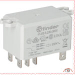
Finder 66.82.8.230.0000 Power Relay: Reliable 30A Solution for HVAC and Industrial Control
Category: Equipment
written by www.mbsmpro.com | January 1, 2026
Finder 66.82.8.230.0000 Power Relay: Reliable 30A Solution for HVAC and Industrial Control
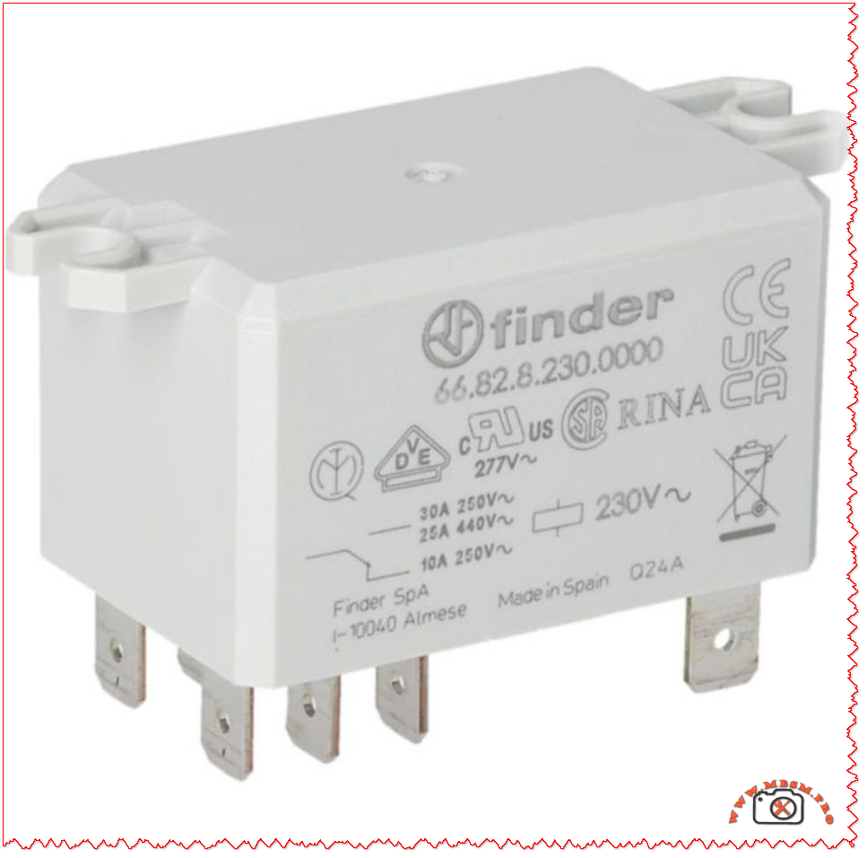
The Finder 66.82.8.230.0000 is a high‑power, flange‑mount relay designed for demanding switching tasks in HVAC, refrigeration and industrial control panels. With a 230 V AC coil and 30 A contact rating, it offers a compact but robust alternative to contactors in many applications.
Product overview
The Finder 66.82 series is a family of 30 A power relays with Faston terminals and reinforced insulation that comply with international safety standards for electrical equipment. The 66.82.8.230.0000 variant pictured is a DPDT (2 changeover contacts) relay with a 230 V AC coil, suitable for single‑phase loads up to 440 V AC.
Mounted on a panel via integrated flanges, this relay is widely used in OEM machines, control panels and HVAC units where reliable separation between the control circuit and the power circuit is essential. Its compact housing and Faston 6.3 × 0.8 mm connections make wiring quick and maintenance friendly for installers and service technicians.
Key electrical specifications
For designers and technicians, the most critical data are contact rating, coil voltage and insulation performance. The table below summarizes the main technical characteristics of the Finder 66.82.8.230.0000 as presented in distributors’ listings and the manufacturer’s catalog.
Specification
Value
Notes
Manufacturer / Series
Finder 66.82
Power relays 30 A series.
Coil voltage
230 V AC
Standard mains control voltage.
Contact configuration
DPDT (2CO)
Two changeover contacts.
Max. switching current
30 A
Per contact set for AC loads.
Max. switching voltage
440 V AC
For power applications.
Terminals
Faston 6.3 × 0.8 mm
For push‑on connectors.
Mounting
Flange mount
For panel or chassis mounting.
Insulation
Reinforced between coil and contacts
According to EN 60335‑1.
These values make the relay particularly suitable for switching compressors, fan motors, heating elements and resistive or slightly inductive loads in HVAC and refrigeration systems.
Typical applications in HVAC and industry
In real‑world installations, the Finder 66.82.8.230.0000 often replaces bulkier contactors in medium‑power circuits where panel space and cost must be optimized. Common uses include:
Switching single‑phase compressors in cold rooms, display cabinets and small chillers up to 30 A at 230–250 V AC.
Controlling electric heaters, defrost elements and fan banks in air‑handling units and rooftop HVAC packages.
Interfacing low‑power thermostats, PLC outputs or electronic boards with mains loads in industrial machinery and building automation.
Because it provides reinforced insulation between coil and contacts, the relay is suitable for applications governed by household and similar equipment standard EN 60335‑1, which is frequently referenced in HVAC and appliance design. This insulation level enhances safety where user‑accessible electronics coexist with high‑voltage power circuits.
Installation and safety guidelines
When integrating this relay into a control panel, technicians should follow the wiring diagrams supplied in the Finder datasheet and the equipment manufacturer’s instructions. Faston terminations must be fully mated with correctly sized push‑on connectors, and conductors should be chosen according to the 30 A rating and ambient temperature in the enclosure.
The relay must be mounted on a flat surface using the dedicated flanges, ensuring adequate clearance for cooling and respecting creepage distances to nearby live parts. As with all power components, switching capacity must be derated for highly inductive loads, frequent cycling or elevated temperatures, conditions that are common in heavy‑duty HVAC duty cycles.
MADEL KCA‑SUB zoning control module: wiring, functions and professional applications
Category: Equipment
written by www.mbsmpro.com | January 1, 2026
MADEL KCA‑SUB zoning control module: wiring, functions and professional applications
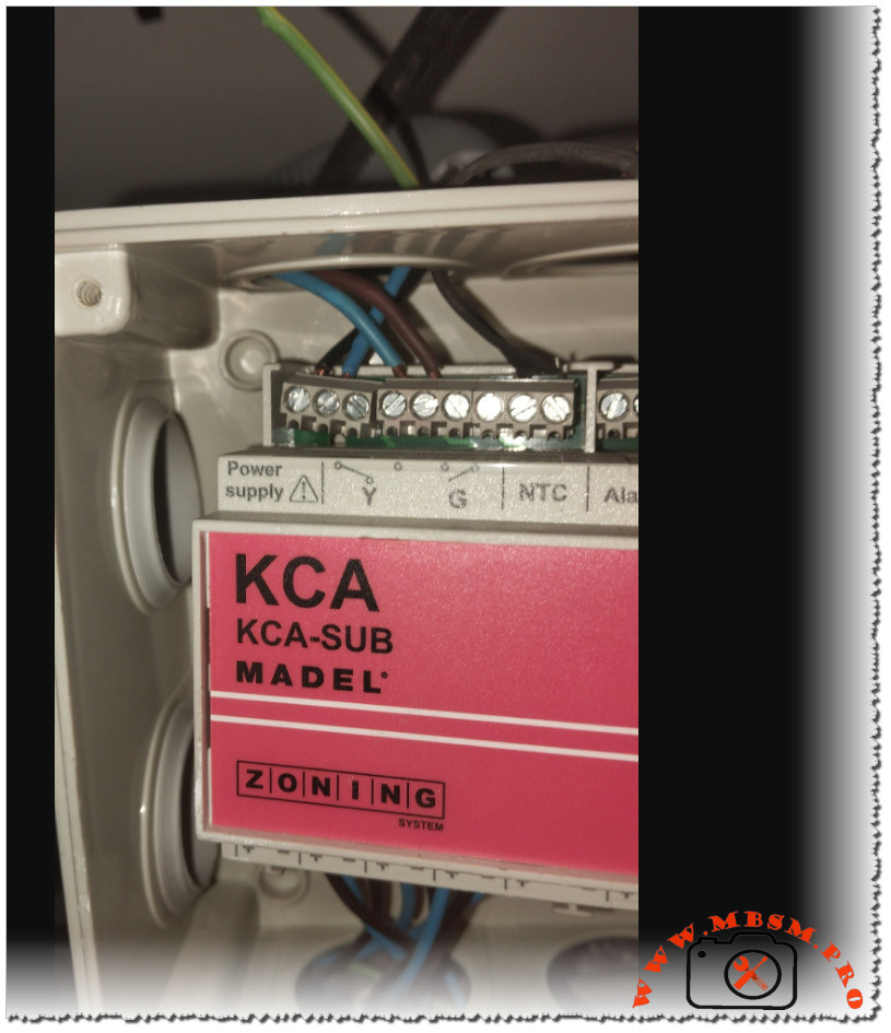
The MADEL KCA‑SUB is an electronic zoning controller designed to manage up to six independent air‑conditioning zones from a single ducted unit, improving comfort and energy efficiency in residential and light‑commercial projects. The photo shows the KCA‑SUB board installed in a junction box, with power, relay outputs and sensor terminals clearly labeled for field technicians.
Overview of the KCA‑SUB zoning system
The KCA‑SUB is part of MADEL’s Zoning System range, which uses motorized dampers and digital thermostats to regulate airflow to each room or zone. Each thermostat communicates with the control board via an RS485 bus, allowing centralized management of temperature and operation modes.
In “sub‑zone” configuration, the KCA‑SUB works on one to six branches of an existing ducted installation without modifying the logic of the main air‑conditioning unit. This makes it suitable for retrofits where only specific rooms need individualized temperature control.
Terminals and wiring shown in the image
On the upper edge of the module, the first block of terminals is reserved for the 230 V power supply and for control relays marked Y and G. According to the installer manual, Y and G are dry contacts intended to interface with the indoor unit’s cooling/heating and fan or start/stop inputs, following the wiring diagram provided by MADEL.
Next to the relay contacts, the board includes an NTC input for the return‑air sensor (typically a 10 kΩ thermistor) and an Alarm output that operates as a normally open potential‑free contact. In case of system fault, this alarm contact closes and can be connected to a BMS, a visual indicator or a safety circuit that shuts down the air‑handling unit.
Zoning channels and communication bus
The controller offers outputs for up to six motorized zone dampers, usually wired with red (positive) and black (negative) conductors for each actuator. The manual specifies a typical cable section between 0.75 and 1.0 mm² and recommends connecting any “master” zone to output 1 to ensure proper reference for system logic.
For communication, the KCA‑SUB uses an AB bus where terminal A is commonly wired in white and terminal B in blue, as also visible in many field installations. This two‑wire RS485 line links the control panel with all digital thermostats and must be daisy‑chained with correct polarity to guarantee stable communication.
Configuration and commissioning
Commissioning begins by supplying 230 VAC to the Power supply terminals and selecting the required number of zones with the rotary selector on the circuit board. Once the number of zones is set, technicians program each digital thermostat with its unique identification address and zone number using the SET‑UP menu described in the manual.
The controller can operate in classic “zoning” mode or in “sub‑zone” mode, where the KCA‑SUB manages only part of the installation while the original thermostat or controller keeps global authority over the unit. Seasonal change‑over between cooling and heating is typically commanded from the master thermostat, which sends the corresponding signal to the control board.
Operating indications and maintenance
Status LEDs on the front edge of the KCA‑SUB provide quick diagnostics for each zone and for the unit relays. In MADEL’s convention, a green LED indicates an open zone, a red LED indicates a closed zone, and illuminated Y or G LEDs mean that the respective relay is activated.
In case of malfunction, installers are instructed to verify wiring of dampers, sensors and the AB bus, then contact MADEL Technical Assistance Service if the fault persists. Regular inspection of damper movement, sensor placement in the return‑air duct and cleanliness of the control box help maintain reliable zoning performance over time.
Key technical data
Feature
Description
Product name
MADEL KCA‑SUB sub‑zone control panel for Zoning System.
Application
Zoning of 1–6 branches on ducted HVAC installations (sub‑zone operation).
Power supply
230 VAC supply on dedicated terminals.
Zone outputs
Up to 6 motorized dampers, red (+) and black (–) wires, 0.75–1.0 mm² conductors.
Communication
RS485 AB bus (A = white, B = blue) for digital thermostats.
Sensors
NTC 10 kΩ return‑air temperature probe on NTC terminal.
Unit control
Y and G relay contacts to interface with indoor unit controls, on/off and mode.
Alarm output
Potential‑free normally open contact, closes in alarm condition.
Electrostatic Paint Sprayer: Precision Coating for Modern Workshops
Category: Equipment
written by www.mbsmpro.com | January 1, 2026
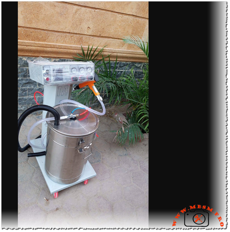
Electrostatic Paint Sprayer: Precision Coating for Modern Workshops
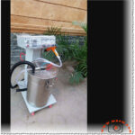
In many metalworking, HVAC and automotive workshops, an electrostatic paint sprayer has quietly become the secret weapon for achieving premium finishes with less paint and less mess. This compact system, often mounted on a mobile trolley with an integrated paint tank and control cabinet, charges each droplet of paint so it is strongly attracted to grounded metal parts. The result is a smooth, uniform coat that wraps around complex shapes while cutting material waste and spray‑booth pollution.
How an electrostatic sprayer works
At the heart of the system is a high‑voltage power supply that charges the paint as it leaves the spray gun nozzle. Charged particles repel each other, creating a fine, even mist that spreads uniformly across the target surface. When the workpiece is correctly grounded, those same particles are pulled in like iron filings to a magnet, covering corners, tubes and hidden edges that are often missed with conventional guns.
A typical workshop installation includes:
A stainless‑steel paint tank with secure lid and fittings for circulation and flushing.
A control column housing electrical and pneumatic controls, often shielded under a clear cover for safety.
Flexible hoses supplying paint and air to the gun, plus return lines for cleaning and color change.
A wheeled base, allowing the whole unit to move between production lines, vehicles or HVAC modules on site.
Key advantages for professional finishers
The biggest reason technicians move to electrostatic spraying is transfer efficiency. Because so much of the paint lands on the part instead of drifting away as overspray, manufacturers report efficiencies up to around 90%, compared with much lower figures for traditional air spray or HVLP equipment. That efficiency translates directly into cost savings on coatings, thinner layers of hazardous waste, and shorter booth cleaning cycles after each job.
Beyond savings, electrostatic systems deliver a noticeably better finish. The wrap‑around effect and consistent atomization create a smooth, uniform film even on complex geometries like compressor bodies, fan housings and tubular frames. This often means fewer passes, reduced risk of runs and sags, and less rework on high‑value components. For businesses like Mbsmgroup that work across HVAC, refrigeration and light industrial applications, that combination of quality and efficiency can be a significant competitive advantage.
Typical applications in metal, HVAC and automotive work
Electrostatic liquid systems are widely used wherever metal parts need durable, professional coatings. In HVAC and refrigeration workshops they are ideal for repainting cabinets, condensers, brackets and custom fabricated parts after repair or modification. In automotive environments, they are used on frames, panels, wheels and accessories where consistent film build is critical. They also appear in general manufacturing, coating everything from furniture frames to machinery guards.
Because the technology works with both solvent‑based and water‑based paints when the right gun and isolation strategy are used, one machine can often serve several product lines. Compact, mobile units – like the one pictured – make it possible for small and medium firms to benefit from the same technology used by large paint shops, without investing in a full robotic or conveyorized system.
Safety, maintenance and best practice
Electrostatic equipment concentrates energy and chemicals in one place, so good practice is essential. All workpieces and hangers must be well grounded for the charge to work and to avoid dangerous sparking; operators should regularly clean hooks, clamps and racks so insulation from dried paint does not build up. Personal protective equipment – mask or respirator, gloves and coveralls – remains mandatory because the process still uses fine aerosols and potentially volatile solvents.
Routine maintenance tasks include flushing paint hoses and the stainless‑steel tank between colors, checking filters, and inspecting the high‑voltage cable and gun body for damage. A simple maintenance log helps track nozzle changes, pump service and safety checks, improving uptime and extending the life of the system in demanding workshop conditions.
Technical overview table
Feature
Typical specification / description
Application method
High‑voltage electrostatic liquid spray gun with adjustable voltage and paint flow.
Transfer efficiency
Often up to about 90% in optimized conditions, reducing overspray and material waste.
Compatible coatings
Solvent‑based and water‑based paints when used with appropriate isolation and hardware.
Ideal use cases
Metal cabinets, frames, HVAC units, machinery, automotive parts and complex geometries.
Mobility and layout
Mobile trolley with stainless tank, control cabinet and hoses for flexible positioning in the shop.