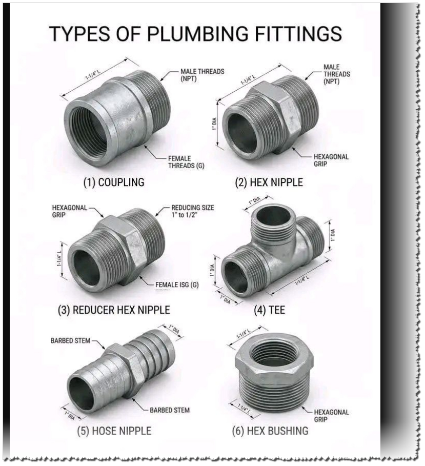
A coupling is used to connect two pipes of the same diameter. It features internal (female) threads on both ends. This is the go-to fitting for extending a straight run of pipe.
2. Hex Nipple
A hex nipple has external (male) threads on both ends. The “hex” refers to the hexagonal section in the middle, which allows a wrench to grip the fitting securely during installation. It is used to connect two female-threaded fittings or valves.
3. Reducer Hex Nipple
Similar to a standard hex nipple, but the two threaded ends are different sizes (e.g., transitioning from a 1″ pipe to a 1/2″ pipe). This allows you to join components of unequal diameters.
4. Tee
A T-shaped fitting with three openings. It is used to split a single line into two separate branches or to combine two lines into one. In the image, this specific tee features male threads on all three ends.
5. Hose Nipple (Barb Fitting)
This fitting is designed to connect a flexible hose to a threaded pipe system.
Barbed Stems: These slide into the hose, and the ridges grip the interior to prevent it from slipping off.
Hex Grip: Used to tighten the fitting into a threaded port.
6. Hex Bushing
A bushing is used to reduce the size of a female threaded opening. It has male threads on the outside and female threads on the inside. You would screw this into a larger port so that a smaller pipe or fitting can be attached to it.
Key Technical Note: Thread Types
The image mentions two common thread standards:
NPT (National Pipe Tapered): Common in North America; the threads are tapered to create a liquid-tight seal.
G (BSP – British Standard Pipe): Common in Europe and internationally; these are parallel threads that usually require a washer or O-ring to seal.
Complete guide to refrigeration compressor thread connections including 7/8″ ACME, 5/8″ suction, 1/2″ discharge, and 1/4″ process ports specifications.
Refrigeration compressor thread connections represent one of the most fundamental yet often misunderstood aspects of HVAC system design. Whether you’re a seasoned technician, equipment engineer, or facility manager, correctly identifying and matching compressor port threads determines the success of your entire cooling system. This comprehensive guide walks through the essential thread types found in modern hermetic and semi-hermetic refrigeration compressors, from industrial freezing units to commercial air conditioning systems.
The thread connection system on a compressor serves a critical purpose: it creates a secure, leak-proof seal between the compressor and refrigeration lines while maintaining system integrity under high pressures. A single mismatched connection can result in refrigerant leaks, system failures, and expensive downtime.
Section 1: What Are Refrigeration Compressor Threads?
H3: The Role of Thread Connections in Compressor Systems
Refrigeration compressors operate under substantial pressure ranges, typically between 150 to 400+ PSI depending on refrigerant type and application. The thread connections must withstand:
Continuous pressure cycles from compressor startup to shutdown
Temperature fluctuations ranging from −30°C to +55°C in typical systems
Mechanical vibration from motor operation
Chemical compatibility with refrigerants (R134a, R404A, R22, etc.)
These extreme conditions demand precision-engineered connections that prevent micro-leaks, which represent the primary cause of premature system failure in refrigeration equipment.
H3: How ACME Threads Differ From SAE Flare Connections
Two primary thread types dominate the refrigeration industry:
Connection Type
Thread Pattern
Sealing Method
Primary Use
Pressure Rating
ACME Thread
Buttress-style, wider flank angles
Metal-to-metal cone contact
Compressor ports (large diameter)
400+ PSI
SAE 45° Flare
Symmetrical, 45° cone angle
Flare nut compression seal
Gauge sets, small lines
300-350 PSI
NPT (Tapered)
Spiraling conical profile
Thread interference seal
Industrial applications (less common in refrigeration)
250-300 PSI
The distinction matters because ACME threads on compressor ports cannot be directly connected to SAE flare fittings without specialized adapter couplings. Attempting this connection will result in:
Immediate leaks due to incompatible cone angles
System pressure loss within hours
Refrigerant discharge into the atmosphere (environmental and regulatory violation)
Compressor damage from low refrigerant flow
Section 2: The Five Standard Compressor Thread Sizes Explained
H3: 7/8″ ACME Thread – The Suction Port
The 7/8″ ACME connection is the largest and most recognizable compressor port. Located on the side or top of the compressor housing, this port carries gaseous refrigerant vapor returning from the evaporator back into the compression chamber.
Specifications:
Thread Diameter: 7/8″ (22.225 mm) outer diameter
Standard Pitch: ACME-16 (16 threads per inch)
Port Orientation: Female ACME socket (compressor side)
Compatible Tubing: 3/4″ to 7/8″ diameter copper lines
Pressure Rating: 400+ PSI (safe for low-pressure suction lines)
Temperature Range: −30°C to +55°C continuous operation
Why 7/8″? This oversized port exists because suction lines carry low-pressure, low-density vapor. The larger diameter reduces flow velocity and minimizes pressure drop, which is critical for compressor efficiency. A restrictive suction line forces the compressor to work harder, increasing energy consumption by 5-15% and reducing cooling capacity.
Technical Advantage: The 7/8″ ACME thread design allows tool-free hand-tightening without creating system leaks, unlike smaller connections that require wrench application.
H3: 5/8″ ACME Thread – The Discharge Port
Located directly opposite the suction port (typically at the compressor top), the 5/8″ ACME discharge connection evacuates high-pressure liquid refrigerant from the compression chamber toward the condenser.
Temperature: Up to +65°C discharge gas temperature
Tubing Size: 1/2″ to 5/8″ diameter copper lines
Critical Distinction: Unlike the suction port carrying pure vapor, the discharge line contains superheated liquid refrigerant at extreme temperatures and pressures. This is why discharge lines are consistently smaller in diameter—the fluid is denser and travels faster through the system.
Engineering Insight: Compressor discharge temperatures can exceed 65°C, sometimes reaching 80°C+ in high-ambient conditions. This heat, if not properly dissipated through the condenser, degrades refrigerant oil viscosity and accelerates seal wear, reducing compressor lifespan by 30-50%.
H3: 1/2″ ACME Thread – Alternative Discharge/Port Configuration
Some compressor models utilize a 1/2″ ACME connection as an alternative discharge port or as a secondary service valve. This slightly smaller connection appears on:
Dual-port compressor designs for system redundancy
Liquid injection systems in capacity-controlled compressors
Specifications:
Thread Diameter: 1/2″ (12.7 mm)
Pressure Rating: 300-400 PSI
Temperature: −20°C to +70°C
Common Application: Scroll and rotary compressor discharge ports
H3: 8/C (1/4″ NPT) Thread – The Process Stub Connection
The 8/C designation, representing an 1/8″ NPT equivalent (approximately 1/4″ flare), serves as a low-pressure service port for charging and diagnostics. This tiny connection is highly specialized and often overlooked by technicians unfamiliar with hermetic compressor design.
Specifications:
Thread Type: 1/8″ NPT (National Pipe Tapered)
Alternate Designation: 8/C or “process tube”
Sealing Method: Thread taper seal (no flare nut required)
Maximum Pressure: 50 PSI safe working pressure
Primary Function: System charging, evacuation, pressure testing
Critical Warning: The process stub is intentionally designed for low-pressure access only. Connecting high-pressure gauges or test equipment to this port risks:
Rupturing the tiny tubing (typically 3-4 mm diameter)
System contamination from non-system fluids
Compressor failure if system pressure spikes during closure
Many technicians have damaged compressors by mistakenly attaching charging hoses to the process tube instead of proper service ports.
H3: 1/4″ SAE Flare Thread – Gauge and Equipment Connection
The 1/4″ SAE flare thread represents the standard connection for refrigerant charging gauges, vacuum pumps, and diagnostic equipment used during system installation and maintenance.
Specifications:
Thread Diameter: 1/4″ SAE (6.35 mm)
Flare Angle: 45° cone (SAE standard)
Sealing Method: Flare nut compression seal
Pressure Rating: 300-350 PSI working pressure
Temperature Range: −20°C to +65°C
Important Note: The 1/4″ SAE flare thread does not directly match compressor ACME ports and requires adapter couplings:
1/4″ SAE Male × 1/2″ ACME Female for discharge line connections
1/4″ SAE Male × 7/8″ ACME Female for suction line connections
These adapters are essential tools that must be included in every technician’s refrigeration toolkit.
Section 3: Comparative Analysis – Thread Types and Applications
H3: ACME vs. SAE: Which Connection Is Better?
This question doesn’t have a simple answer because both thread types serve different system purposes:
Verdict: For compressor ports (7/8″, 5/8″, 1/2″), ACME threading is superior due to engineered reliability and pressure capacity. For diagnostic and service equipment connections, SAE flare remains the industry standard because the pressure demands are lower.
Section 4: Identification Guide – How to Recognize Thread Types
H3: Visual Identification Methods
ACME Thread Characteristics:
Distinctive flat-topped threads (not pointed like SAE)
Wider thread flanks with gentler angle transitions
Modern refrigerants compatible with ACME thread systems:
Refrigerant
Ozone Depletion Potential
Global Warming Potential
Compatibility with ACME Threads
Typical Application
R134a
0 (phased in)
1,300
✓ Excellent
Automotive, commercial chillers
R404A
0
3,922
✓ Excellent
Low-temperature freezing, cascade systems
R407C
0
1,774
✓ Good
Retrofit for R22 systems
R290 (Propane)
0
3
✓ Good (special care)
Emerging: ultra-low GWP
Note: Transitioning from older refrigerants (R22) to modern alternatives may require updating system components and thread configurations. Consult compressor manufacturers for compatibility matrices.
Section 9: Expert Tips from HVAC Professionals
H3: Industry Best Practices Summary
From 20+ years of experience in refrigeration service, the most critical recommendations are:
Always carry adapter couplings in your service kit (SAE × ACME combinations cover 95% of connections)
Invest in a calibrated torque wrench specifically designed for refrigeration work (prevents over-tightening)
Use a vacuum pump to evacuate connections before charging (removes moisture that causes acid formation)
Schedule preventive maintenance annually to inspect thread integrity (catches corrosion and vibration issues early)
Document compressor specifications when performing initial installation (saves troubleshooting time during future repairs)
H3: Common Professional Mistakes to Avoid
Reusing old tubing with questionable flare integrity
Skipping nitrogen purging during brazing (causes black oxide scale buildup)
Assuming all 7/8″ ports are identical (some models use NPT instead of ACME)
Over-tightening connections under time pressure (can crack ports)
Mixing refrigerants during charging (creates incompatible oil suspensions)
Section 10: Specifications Comparison Tables for Reference
H3: Master Specification Reference
For quick reference, here’s a comprehensive comparison of all standard compressor thread types:
Parameter
7/8″ Suction
5/8″ Discharge
1/2″ Port
8/C Process
1/4″ SAE Gauge
Thread Type
ACME
ACME
ACME
1/8″ NPT
SAE 45° Flare
Nominal Diameter
22.2 mm
15.9 mm
12.7 mm
6.4 mm
6.35 mm
Threads Per Inch
16 TPI
16 TPI
16 TPI
27 TPI
16 TPI
Operating Pressure
400+ PSI
200-350 PSI
300-400 PSI
50 PSI max
300-350 PSI
Temperature Range
−30°C to +55°C
−20°C to +65°C
−20°C to +70°C
−30°C to +40°C
−20°C to +65°C
Typical Tubing
3/4″-7/8″ OD
1/2″-5/8″ OD
3/8″-1/2″ OD
3 mm ID
1/4″ SAE flare
Seal Type
Metal-to-metal
Metal-to-metal
Metal-to-metal
Thread taper
Flare nut compression
Function
Low-pressure return
High-pressure discharge
Secondary/liquid
System charging
Diagnostic equipment
Leak Probability
Very low (0.3%)
Low (0.8%)
Low (1.2%)
Moderate (3%)
Moderate (2-3%)
Conclusion: Making Informed Decisions About Compressor Connections
Understanding refrigeration compressor thread connections transforms your ability to design, install, and maintain reliable cooling systems. The distinction between ACME and SAE threading, the proper role of each port size (7/8″, 5/8″, 1/2″, 1/4″), and the critical safety considerations for process tubes empowers technicians and facility managers to make informed purchasing decisions and avoid expensive system failures.
The investment in proper components, quality adapter couplings, and professional installation practices pays dividends through:
Eliminated refrigerant leaks (saving thousands in replacement costs)
Extended compressor lifespan (15+ years vs. 5-7 years for poorly maintained systems)
Improved system efficiency (reduced energy consumption, lower operating costs)
Full regulatory compliance (EPA certification, leak documentation, environmental responsibility)
Enhanced safety (properly sealed systems reduce pressure risks)
Whether you’re sourcing equipment for a new industrial refrigeration facility or troubleshooting a struggling commercial cooling system, the technical knowledge contained in this guide provides a foundation for excellence in refrigeration system management.
For additional technical resources, detailed equipment specifications, and professional consultation on refrigeration system design, explore our complete technical documentation and equipment database at Mbsmpro.com.
Auto Draft mbsmpro
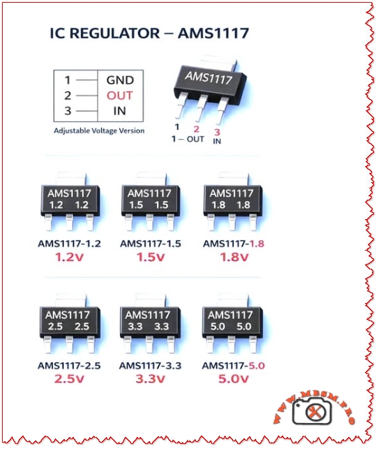
AMS1117 Voltage Regulator
Category: Equipment
written by www.mbsmpro.com | April 12, 2026
AMS1117 Voltage Regulator: Common Mistakes, Practical Guide, and Engineering Best Practices
Overview The AMS1117 family of linear voltage regulators (fixed and adjustable versions) is ubiquitous in electronics projects, embedded systems, and power-supply rails. Despite its popularity, technicians and hobbyists repeatedly make the same installation and design mistakes that cause overheating, instability, and premature failure. This article explains those common mistakes, gives engineering‑grade corrections, compares AMS1117 variants with alternatives, and supplies practical tables, values, and installation checklists you can use in a WordPress technical post.
Why AMS1117 Is Widely Used
Simple three‑pin package (GND, OUT, IN) makes board layout straightforward.
Thermal plan: Heatsink area, copper pour, and airflow if W.
Layout: Short traces, wide copper, thermal vias under package for SMD variants.
Protection: Input TVS, series fuse, reverse‑polarity protection.
Testing: Thermal imaging under full load; measure output ripple and transient response.
Thermal Calculation Example
Given: VIN = 12 V, VOUT = 5 V, ILOAD = 0.8 A
Dissipation:
Implication: 5.6 W requires substantial heatsinking; AMS1117 in a TO‑220 or SOT‑223 without heatsink will overheat. Consider switching regulator.
Comparison Table: AMS1117 vs. Common Alternatives
Attribute
AMS1117 (Linear)
LM2596 (Buck)
LDO Modern (e.g., MIC5219)
Efficiency at 5 V out from 12 V in
~42%
~85–95%
~42–60%
Typical max current
~1 A (thermally limited)
3 A (switching)
500 mA–1 A
Output noise
Low‑mid
Higher switching noise
Low
Board complexity
Low
Higher (inductor, diode, caps)
Low
Thermal stress
High for large VIN–VOUT
Low
Moderate
Best use case
Small loads, simple designs
High current, large step‑down
Low‑noise low‑current rails
When to Choose AMS1117 (Use Cases)
Low‑power microcontroller rails (e.g., 3.3 V at < 300 mA).
Simple sensor boards where VIN is close to VOUT (small voltage drop).
Prototyping and low‑volume products where cost and simplicity matter.
When to Avoid AMS1117 (Alternatives)
High current (>1 A) or large VIN–VOUT difference — use a buck converter.
Battery‑powered designs where efficiency is critical — use switching regulator.
Very low noise analog rails — choose a precision LDO with low noise spec.
Layout and PCB Best Practices
Place caps within 2–5 mm of regulator pins.
Use wide input and output traces (or pour copper) to reduce voltage drop and improve heat spreading.
Add thermal vias under SMD packages to move heat to inner or bottom copper.
Keep sensitive analog traces away from the regulator’s hot copper and switching nodes (if present).
Label polarity clearly and include test points for VIN, VOUT, and GND.
Testing and Validation Steps
No‑load test: Verify VOUT with no load; check for oscillation.
Step‑load test: Apply sudden load changes and measure transient response.
Thermal test: Run at maximum expected load for 30 minutes; measure case and PCB temps.
Ripple test: Measure output ripple with oscilloscope; ensure within tolerance for your circuit.
Fault test: Simulate short‑circuit and overvoltage to confirm protection behavior.
Common Failure Modes and Troubleshooting
Symptom: Output drops under load → Check thermal shutdown, insufficient input voltage, or current limit.
Symptom: Output noisy or oscillating → Check output capacitor ESR and placement.
Symptom: Device hot to touch → Check power dissipation calculation and add heatsink or switch to buck converter.
Symptom: No output → Check input presence, reverse polarity protection, and solder joints.
Engineering Notes and Practical Tips
Combine capacitors: a 0.1 µF ceramic in parallel with a 10 µF electrolytic gives best high‑ and low‑frequency performance.
Derate current: assume 70–80% of the absolute max in real designs unless thermal path is proven.
Use thermal simulation or simple hand calculations to size copper pour and heatsink.
Document expected VIN range and include transient protection if VIN can spike (e.g., automotive or industrial environments).
Focus Keyphrase
AMS1117 common mistakes thermal design decoupling capacitor layout oscillation protection buck alternative 1.2V 1.8V 3.3V 5V regulator
SEO Title
Mbsmpro.com, AMS1117 Voltage Regulator, Common Mistakes, Thermal Design, 1.2V–5.0V, Decoupling, Layout, Alternatives
Meta Description
Avoid overheating and instability with AMS1117 regulators. Learn the most common mistakes, thermal calculations, capacitor recommendations, PCB layout tips, and when to choose a buck converter instead.
AMS1117, Voltage Regulator, LDO, Decoupling, Thermal Design, PCB Layout, Buck Converter, 3.3V, 5V, Mbsmgroup, Mbsm.pro, mbsmpro.com, mbsm, Electronics, Power Supply
Excerpt (first 55 words)
AMS1117 linear regulators are simple and cheap, but common mistakes—missing decoupling, poor thermal planning, and long traces—cause instability and overheating. This guide explains capacitor choices, power dissipation math, PCB layout rules, testing steps, and when to switch to a buck converter for efficiency and reliability.
Focus Keyphrase: flaring tool bar type multiple size openings adjustable T-handle metal tube flare HVAC plumbing connection guide
SEO Title: Flaring Tool Guide: How to Use Bar-Type Tool with Multiple Size Openings & T-Handle | Mbsmpro
Meta Description: Complete guide to using a bar-type flaring tool. Learn how the multiple size openings and adjustable T-handle create secure, leak-proof flares on copper tubing for HVAC and plumbing.
Excerpt: A bar-type flaring tool is essential for creating leak-proof connections in copper tubing. Its multiple size openings handle various tube diameters, while the adjustable T-handle provides precise control. This guide covers proper technique, common mistakes, and tool selection.
Mastering the Bar-Type Flaring Tool: Your Guide to Perfect, Leak-Proof Connections
If you’ve ever worked with refrigeration lines, hydraulic systems, or even some plumbing applications, you know that a secure connection isn’t just about tightening a nut—it’s about creating a perfect mating surface. That’s where the flaring tool becomes indispensable. Specifically, the bar-type flaring tool with multiple size openings and an adjustable T-handle is the professional’s choice for reliability and consistency. This isn’t a gadget; it’s a precision instrument for creating the 45-degree flares that form the foundation of leak-free systems.
Let’s break down why this specific design is superior and how to use it to achieve flawless results every time.
Anatomy of a Professional Flaring Tool: Why Design Matters
A generic, clamp-style flaring tool might get the job done once or twice, but for consistent, reliable results under varying conditions, the bar-type design is king. Here’s what each feature delivers:
Feature
Function & Engineering Benefit
Multiple Size Openings
A solid steel bar with a series of precision-drilled holes (e.g., for 1/4″, 3/8″, 1/2″, 5/8″ OD tubing). This ensures the tube is clamped squarely and concentrically, which is critical for a uniform flare.
Adjustable T-Handle
A threaded screw with a T-handle that drives the flaring cone (or “pilot”). The “adjustable” aspect allows you to control the feed rate and pressure precisely, preventing over-flaring or under-flaring.
Flaring Cone (Pilot)
This is the hardened, 45-degree cone that is driven into the tube end. It is typically separate from the handle and matches the specific flare angle (45° for SAE/JIC fittings common in HVAC).
Solid Steel Bar Construction
Provides massive rigidity compared to yoke-style tools. This prevents flex during the flaring process, which can lead to off-center or wrinkled flares.
Step-by-Step: The Correct Flaring Technique
Using this tool correctly is a methodical process. Rushing leads to leaks and wasted materials.
Cut & Prep: Cut the copper tube perfectly square using a tube cutter. Then, remove all internal and external burrs using a deburring tool or file. An internal burr is a guaranteed flow restriction.
Select & Insert: Choose the correct hole in the bar that matches your tube’s outer diameter (OD). Slide the bar’s clamping mechanism over the tube and tighten it snugly. The tube should protrude slightly above the bar—usually the thickness of the flare nut.
Lubricate & Position: Apply a tiny drop of refrigeration oil or light lubricant to the 45-degree flaring cone. This reduces friction and creates a smoother finish. Place the cone into the end of the tube.
The Flaring Process: Thread the adjustable T-handle into the bar until it contacts the cone. Then, using steady, even pressure, turn the handle to drive the cone into the tube. Go slowly, especially on the final turns. You will feel a distinct increase in resistance when the flare is fully formed.
Inspect: Unscrew the handle, remove the bar clamp, and inspect your work. A perfect flare will be concentric, smooth, and have a matte-silver appearance with no cracks, wrinkles, or tool marks.
Bar-Type vs. Yoke/Clamp-Type: A Critical Comparison
To understand the value, let’s compare it to the more common (and cheaper) alternative.
Aspect
Bar-Type Flaring Tool
Standard Yoke/Clamp-Type Tool
Stability & Precision
Excellent. Solid bar prevents flex, ensuring a concentric flare.
Poor. The clamp can twist or flex, leading to off-center, “cocked” flares.
Consistency
High. Repeatable results due to rigid design and precise holes.
Low. Results vary based on user grip and tool wear.
Durability
Very High. Solid steel construction lasts for decades.
Moderate. Cast components and pivots can wear or break.
Best For
Professional use, critical applications (refrigeration, fuel gas, hydraulic).
Occasional DIY use for non-critical plumbing (like water softener lines).
Cost
Higher initial investment.
Lower initial cost.
The Verdict: For any application where a leak means lost refrigerant, safety hazard, or system failure, the bar-type tool is the only responsible choice. The initial cost is offset by the elimination of costly callbacks and material waste from bad flares.
Professional Benefits, Advice, and Common Pitfalls
Benefits of Mastering This Tool:
Eliminate Callbacks: A perfect flare is a permanent, leak-free connection. This builds customer trust and saves money.
Faster Work: With practice, making a perfect flare becomes a quick, one-step process, speeding up installation.
Material Savings: You’ll stop ruining expensive tubing sections with flawed flares that must be cut off and re-done.
Critical Professional Notice & Warnings:
DO NOT Skip Deburring: This is the #1 mistake. The internal burr will cause turbulence, trap debris, and ultimately lead to compressor or valve failure.
Use the Right Lubricant: A drop of clean refrigerant oil is ideal. Do not use grease, which can contaminate a system.
Avoid Over-Flaring: When the T-handle gets very hard to turn, stop. Forcing it further can thin and crack the copper, creating a weak point.
Match the Flare to the Nut: Always test-fit the flare nut before making the flare to ensure the tube is protruding the correct amount. The finished flare should sit snugly inside the nut.
Final Recommendation: View a high-quality bar-type flaring tool not as an expense, but as an investment in your craftsmanship. It is a fundamental tool that pays for itself by ensuring the integrity of the most critical junctions in any system you build. Pair it with a good tube cutter and reamer, and you have the holy trinity for perfect tubing work.
Flare Cross-Section Diagram: Search for “SAE 45 degree flare cross section diagram” on engineering or automotive hydraulic sites like Parker.com or Swagelok.com.
Sequence of Flare Formation: Look for “copper tube flaring sequence photos” on professional tool manufacturer sites like RIDGID.com or ImperialTools.com.
Bad vs. Good Flare Visual Guide: Search for “flaring defects comparison chart” on HVAC training portals like HVAC School or ESCO Institute.
PDF/Catalog Resources (Verified Sources):
RIDGID Tool Instruction Manual: Visit the RIDGID Tools support page and search for your specific flaring tool model (e.g., “No. 454-R”) to download the official, detailed instruction and safety PDF.
ESCO Institute “Refrigeration Piping” Manual: Search for “ESCO pipe and tube bending flaring pdf” for comprehensive professional training material on proper techniques.
SAE International Standard J533: For technical specifications, searching “SAE J533 flare fittings standard” will lead to the definitive documents governing flare design and dimensions.
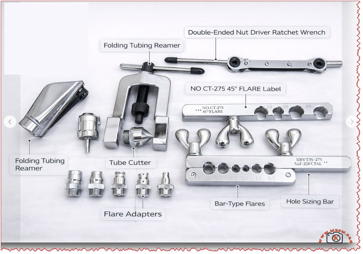
Meta Description: Professional review of the NOCT-27545 ratchet wrench & NRVT35-275 flaring tool kit. Learn how to use folding tubing reamers, bar-type flare tools, and hole sizing bars for HVAC work.
Excerpt: The NOCT-27545 ratchet wrench and NRVT35-275 flaring tool represent specialized HVAC instrumentation. This guide explains their functions, from creating perfect 45° flares to reaming tubing and driving fasteners in tight spaces, ensuring leak-free, professional installations.
NOCT-27545 & NRVT35-275 Tool Guide mbsmpro
HVAC Tool Mastery: Decoding the NOCT-27545 Ratchet Wrench and NRVT35-275 Flaring Kit
Every seasoned HVAC and refrigeration technician knows that the difference between a leak-prone, amateur installation and a flawless, professional one often comes down to the specialized tools in their bag. While flashy power tools get attention, it’s the precision instruments—like those in a comprehensive flaring and driving kit—that ensure longevity and reliability. Today, we’re breaking down a set of tools centered around two key items: the NOCT-27545 double-ended nut driver ratchet wrench and the NRVT35-275 bar-type flaring tool kit.
These aren’t generic hardware store finds; they’re purpose-built for the specific, demanding tasks of refrigeration and gas line work.
Core Tool Analysis: Function and Specification Breakdown
Let’s dissect the primary tools indicated, translating model numbers into practical understanding.
1. The NOCT-27545: The Double-Ended Ratchet Wrench
This tool solves a common field problem: accessing fasteners in confined spaces behind linesets or inside tight equipment compartments.
Feature
Specification / Benefit
Design
Double-ended, reversible ratchet mechanism.
Drive Sizes
Typically features two most-used sizes (e.g., 1/4″ and 5/16″ hex).
Primary Use
Installing service valves, panel screws, solenoid valves, and other fittings where a full swing of a standard driver is impossible.
Advantage over Standard Driver
The ratcheting action allows you to tighten or loosen nuts without removing the tool, saving immense time and frustration in tight quarters.
Comparison to Standard Tools: A standard nut driver requires ~30 degrees of clearance for repositioning. In a tight spot, you might get one partial turn before having to remove and reposition it. The NOCT-27545 ratchet allows for full, continuous torque application with as little as a 5-degree swing, making it indispensable for condenser or evaporator service.
2. The NRVT35-275: Bar-Type Flaring Tool Kit
This is the heart of leak-free connection work for soft copper tubing (Type L, ACR). The “45” in related labels signifies the 45-degree flare standard for SAE/JIC fittings, ubiquitous in HVACR.
Component (from image)
Critical Function
Bar-Type Flaring Tool (Main Body)
Holds the tubing secure in precise, sized holes for a consistent flare. Superior to cheaper clamp-style tools for repeatability.
Flare Adapters (45° Cone)
The forming tool that is pressed/driven into the clamped tube end to create the actual 45-degree flare shape.
Hole Sizing Bar
A reference tool with graduated holes to quickly verify the outer diameter of tubing, ensuring you use the correct clamp hole.
Folding Tubing Reamer
Used after cutting tubing with a tube cutter to remove the internal burr. This is non-negotiable. A left-in burr creates turbulence, restricts flow, and can trap debris.
The Critical Path to a Perfect Flare: A Step-by-Step Process
Using these tools correctly is a systematic process. Here’s how they work together:
Cut: Use a sharp tube cutter (like the S42-LDYCTAL implied) for a square, clean cut. Never use a hacksaw for this step.
Ream: Immediately deploy the folding tubing reamer. Insert it into the tube end and rotate to cleanly remove the internal burr. Deburr the outside edge lightly.
Size: Double-check your tube’s OD using the hole sizing bar. Match it exactly to the corresponding hole on the flaring bar.
Clamp: Insert the tube into the correct hole on the bar-type flaring tool, leaving the appropriate amount of tube protruding (typically the height of the flare nut).
Flare: Apply a drop of refrigerant oil to the flare adapter’s 45-degree cone. Screw the adapter into the bar and drive it down smoothly until it forms a complete flare. Do not over-tighten.
Inspect: A perfect flare will be concentric, smooth, and have a uniform matte finish. No cracks, wrinkles, or tool marks should be present.
Benefits, Professional Advice, and Common Pitfalls
Benefits of Using This Specialized Kit:
Leak Prevention: A properly made flare is the first and most critical line of defense against refrigerant leaks.
Efficiency: The ratchet wrench and integrated tools speed up installation and service work dramatically.
Professional Results: Consistency is key. These tools provide repeatable, manufacturer-spec results every time.
Professional Notice & Critical Warnings:
Material Matters: These tools are designed for soft copper tubing. Do not attempt to flare hard-drawn copper or other metals without specific, rated tools.
The Reamer is Not Optional: Skipping the reaming step is the #1 cause of contamination-related failures and flow restriction. The small burr can break off and travel into a metering device.
Flare Inspection: Always inspect the flare visually and with a gauge if possible before assembly. A flawed flare must be cut off and re-done.
Torque Specs: When connecting the flare nut, use a torque wrench according to the fitting manufacturer’s specifications. Over-tightening can shear the flare, and under-tightening will guarantee a leak.
Value Comparison to Universal Kits: While all-in-one “HVAC tool kits” are available, they often compromise on the quality of these critical forming tools. A dedicated, professional-grade bar-type flaring kit (like the NRVT series) and a precision ratchet driver (like the NOCT) will outperform universal kits in durability, result quality, and ease of use on the job daily. Investing in these separates often costs less in the long run than replacing a failed multi-tool.
Final Recommendation: For any technician serious about refrigeration or fuel gas line work, a high-quality bar flaring tool and a reliable double-ended ratchet are not just purchases; they are foundational investments in your craft and reputation. Master these tools, and you eliminate one of the most common failure points in any system you install.
Sequence of a Perfect Flare: Search for “step by step bar flaring tool process” on professional tool manufacturer sites like RIDGID.com, ImperialTools.com, or YellowJacket.com.
Internal Burr Diagram: Look for “tube cutting internal burr diagram” on educational engineering or HVAC training sites like ESCO Institute or HVAC School.
Flare Inspection Gauge: Search for “SAE 45-degree flare inspection gauge” on supplier sites like Johnstone Supply or United Refrigeration.
PDF/Catalog Resources (Verified Sources):
RIDGID Flaring Tool Manual: Visit the RIDGID Tools website and search for “Flaring Tool Instruction Sheet” for official, detailed usage and safety PDFs.
ESCO Institute Refrigeration Piping Handbook: Search for “ESCO refrigerant piping practices PDF” for comprehensive guides on tubing preparation, which heavily features flaring and reaming procedures.
SAE J514 Hydraulic Flare Fitting Standards: For the truly technical, searching “SAE J514 standard” will lead to the definitive specification documents for 45-degree flare fittings.
SEO Title Mbsmpro.com, Spot Welding Machine Circuit, Half Wave Rectifier, Transformer, Timer, Electrodes, Water Cooled, AC to DC
Meta Description Explore the spot welding machine circuit with half-wave rectifier, step-down transformer, adjustable timer, and water-cooled electrodes. Detailed diagram breakdown, components, comparisons for DIY builders and pros.
Excerpt Fabricators rely on the classic spot welding machine circuit featuring a half-wave rectifier for reliable AC-to-DC conversion. A heavy-duty step-down transformer boosts current for nugget formation, while an adjustable timer controls squeeze, weld, and hold phases precisely.
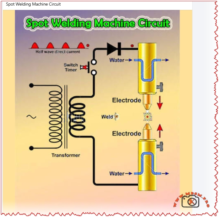
Spot Welding Machine Circuit: Complete Breakdown and Build Guide
Workshop pros and DIY enthusiasts build spot welders around a straightforward half-wave rectifier circuit that turns household AC into high-amperage pulses for clean metal joins. This design prioritizes simplicity with water-cooled electrodes to handle heat during extended runs. Transformers step down voltage while ramping current to thousands of amps briefly.
Core Components Table
Component
Function
Key Specs
AC Input
Supplies mains power (220-240V 50Hz)
Via main switch
Half-Wave Rectifier (Diode)
Converts AC to pulsating DC
Prevents backflow
Step-Down Transformer
Boosts current (50:1 ratio typical)
Primary: 220V, Secondary: 2-12V
Timer Circuit
Controls weld cycle (squeeze/weld/hold)
Adjustable 0-99 cycles
Electrodes
Apply pressure and current to workpiece
Copper, water-cooled arms
Water Cooling
Dissipates heat from electrodes/transformer
Inlet/outlet ports
The rectifier diode handles peak currents up to 500A, feeding the transformer’s low-voltage secondary for nugget fusion in 0.1-1 second bursts.
Circuit Operation Steps
Power flows from AC mains through the half-wave switch to the rectifier diode, producing unidirectional current. This charges the transformer primary, inducing high-current low-voltage output on the secondary side. Timer triggers the cycle: electrodes squeeze sheet metal, current pulses to melt contact point, then hold for solidification. Water lines prevent electrode mushrooming.
Comparison: Half-Wave vs Modern Spot Welder Circuits
Traditional half-wave designs shine for low-cost builds but lag in precision. Check this matchup:
Circuit Type
Rectification
Efficiency
Weld Quality
Cost
Best For
Half-Wave (Classic)
Single diode
40-50%
Good for thin sheets
$50-200
DIY battery tabs
Full-Wave Bridge
4 diodes
80%
Consistent nuggets
$100-300
Auto body panels
MFDC Inverter
IGBT + MF Transformer
90%+
Deep penetration
$2k+
Factory production
Capacitor Discharge
Supercaps/MOSFET
Pulsed 1000A+
Battery packs
$20-100
18650 cells
Half-wave rectifier edges out capacitor types for continuous duty on thicker steel (up to 3mm), though full-wave cuts ripple for smoother welds. Inverter MFDC slashes transformer size by 70% but demands complex controls.
Value Comparison Across Builds
Budget spot welders deliver pro results without factory prices. Factor in materials:
Build Type
Transformer Cost
Max Current (A)
Sheet Thickness (mm)
Total Build Cost
ROI (Jobs/Year)
DIY Half-Wave
$30 (microwave salvage)
1000-2000
0.5-2.0
$100
50+
Full-Wave Kit
$80
1500-3000
0.8-3.0
$250
100
Capacitor DIY
$10 (supercaps)
500-1500 pulse
0.1-1.0 (Ni strips)
$50
200 (batteries)
MFDC Pro
$1000
10k+
1-6
$5000+
1000
Salvage microwave transformers slash costs 80%, paying back in 10 battery pack jobs. Full-wave boosts duty cycle 2x over half-wave for sheet metal shops.
Safety and Troubleshooting Tips
Insulate primaries to avoid shocks; fuse at 30-50A. Monitor electrode force (2-5 kg) to dodge expulsion. Common fixes: replace diode for no DC output, adjust timer pot for short welds. Run cooling water at 2-5 L/min.
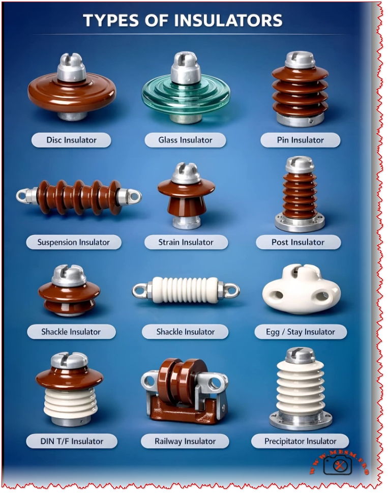
Mbsmpro.com, Electrical Insulators, Disc, Glass, Pin, Suspension, Strain, Post, Shackle, Egg, DIN T/F, Railway, Precipitator, Overhead Line, High Voltage, Porcelain
Overview of Electrical Insulators in Overhead Power Systems
Electrical insulators are critical components that keep high‑voltage conductors mechanically supported while preventing dangerous current leakage to poles, towers, or the ground. A well‑designed insulator system improves network reliability, reduces outages, and protects people, equipment, and the environment. Modern networks use a family of specialized insulators, each optimized for a specific mechanical duty, voltage level, and pollution environment.
Main Types of Line Insulators
Engineers classify line insulators by how they are mounted and how they carry mechanical load along the conductor path. The list below matches the most widely used designs in transmission and distribution systems.
Disc insulator (porcelain or glass) used as basic element in suspension and strain strings above 33 kV.
Glass insulator disc offering high pollution resistance and easy visual detection of damage.
Pin insulator mounted rigidly on crossarms, typically up to about 33 kV.
Suspension insulator string built from multiple discs for medium and high‑voltage lines.
Strain insulator string placed at line angles, dead‑ends, and river crossings to handle high tension.
Post insulator used vertically on poles or substations where compact construction is required.
Shackle (spool) insulator for low‑voltage distribution and service drops in urban networks.
Egg or stay insulator inserted in guy wires to keep pole stays safely insulated near ground level.
DIN transformer (DIN T/F) bushing‑type insulator for transformer terminations in accordance with IEC/EN dimensions.
Railway insulator designed for catenary and contact‑wire systems in electrified traction lines.
Precipitator insulator tailored for electrostatic precipitators in power plants and heavy industry.
Technical Characteristics and Applications
Different line locations impose very different combinations of electrical stress, mechanical tension, and environmental exposure. Selecting the right insulator type is therefore a design decision that directly affects line lifetime and maintenance cost.
Typical service applications
Disc / suspension / strain: High‑voltage overhead lines (33–765 kV) where flexibility, modularity, and easy replacement are required.
Pin / post: Sub‑transmission and medium‑voltage feeders where compact profile and rigid support are important.
Shackle / egg: Low‑voltage networks and guy wires where insulation distances are small but mechanical shock can be high.
DIN T/F / precipitator / railway: Substations, power plants, and traction systems where insulators work as bushings, support insulators, or current‑collector supports under strong pollution and vibration.
Key design parameters
Engineers usually evaluate insulators using a set of standardized parameters.
Rated voltage and creepage distance to prevent flashover under wet and polluted conditions.
Mechanical failing load (tension or cantilever) to withstand conductor weight, wind and ice loads, and short‑circuit forces.
Material choice (porcelain, toughened glass, or composite polymer) according to climate, pollution level, and maintenance strategy.
Standard compliance such as IEC 60383 or ANSI C29 to guarantee interchangeability across manufacturers.
Comparison of Porcelain, Glass, and Composite Insulators
Material selection is often as important as insulator geometry, especially in corrosive or coastal environments. The table below summarizes the most relevant differences for transmission designers.
Material type
Electrical performance
Mechanical behavior
Pollution & aging
Typical use cases
Porcelain
Very good dielectric strength; proven on all voltage levels.
High compressive strength but relatively brittle under impact.
Stable over decades, but glaze can accumulate pollution and needs periodic washing.
Traditional choice for pin, post, disc, and shackle insulators in most climates.
Toughened glass
Excellent surface insulation and low aging; defects are easy to see through transparency.
High tensile strength; discs shatter completely when damaged, simplifying inspection.
Very resistant to pollution; smooth surface reduces leakage current.
High‑voltage suspension and strain strings, especially in polluted or coastal regions.
Composite polymer
Good hydrophobic surface and light weight; suitable for long spans.
Flexible core provides high impact resistance and reduced risk of brittle failure.
Excellent in severe pollution, but long‑term UV and weathering performance still monitored.
Long‑span transmission, compact lines, and areas where low maintenance is critical.
Performance Comparison of Insulator Types
Beyond material choice, the functional type of insulator strongly influences line design, outage statistics, and maintenance planning. The next table compares several key types that appear together in many network diagrams.
Insulator type
Typical voltage range
Main mechanical duty
Installation location
Strengths
Limitations
Disc / suspension
33–765 kV overhead lines.
Carries conductor tension along flexible string.
Tower crossarms and dead‑end towers.
Modular design, easy to adapt voltage by adding discs.
Requires more hardware and careful string design.
Pin
Up to about 33 kV.
Supports conductor vertically on crossarm.
Wooden or steel poles in distribution systems.
Simple and low cost for lower voltages.
Cost and weight rise quickly above 33 kV; limited creepage.
Post
11–245 kV depending on design.
Rigid support with cantilever loading.
Compact lines and substation busbars.
Saves vertical space and allows closer phase spacing.
Less flexible than suspension strings under large movements.
Shackle
Low voltage distribution (typically ≤ 11 kV).
Handles small spans and angle points on LV lines.
Wooden poles, service drops, building entries.
Robust, compact, easy to install.
Not suitable for high tension or high voltage.
Egg / stay
LV and MV guy wires.
Isolates stay wire from ground side tension.
Between pole and earth anchor in stays.
Improves safety at ground level and near roads.
Must be correctly positioned to avoid flashover.
Railway
15–25 kV AC or 1.5–3 kV DC traction systems.
Supports catenary and contact wire under dynamic load.
Masts, portals, and tunnels in electrified routes.
Designed for vibration, pollution, and frequent pantograph contact.
Requires strict dimensional control to keep pantograph interaction stable.
Precipitator
Up to several tens of kV DC.
Isolates discharge electrodes and collecting plates.
Electrostatic precipitators in power and cement plants.
High resistance to contamination by dust and flue gases.
Needs special glazing and shapes to limit dust accumulation.
SEO‑Optimized Focus Keyphrase, Title, Meta and Slug
Focus keyphrase (Yoast SEO) types of electrical insulators disc glass pin suspension strain post shackle egg stay railway precipitator overhead line applications
SEO title (Yoast SEO) Types of Electrical Insulators: Disc, Glass, Pin, Suspension, Strain, Post, Shackle, Egg, Railway and More | Mbsmpro.com
Meta description (Yoast SEO) Explore all major types of electrical insulators—disc, glass, pin, suspension, strain, post, shackle, egg, railway and precipitator. Understand ratings, materials and applications to design safer overhead lines.
Tags electrical insulators, disc insulator, glass insulator, pin insulator, suspension insulator, strain insulator, post insulator, shackle insulator, egg insulator, stay insulator, railway insulator, precipitator insulator, porcelain insulator, glass disc insulator, composite insulator, overhead line design, high voltage transmission, power distribution, Mbsmgroup, Mbsm.pro, mbsmpro.com, mbsm
WordPress Excerpt (first 55 words)
Electrical insulators are fundamental safety components in overhead transmission and distribution networks, keeping high‑voltage conductors mechanically supported while blocking dangerous leakage currents. This article explains the main types of electrical insulators—disc, glass, pin, suspension, strain, post, shackle, egg, railway and precipitator—and compares their materials, voltage ratings, and ideal applications for modern power systems.
In the world of air conditioning maintenance, control is everything. Whether you are an HVAC technician diagnosing a fault or a homeowner tired of losing the remote, the Fitco Smart Control Kit represents the perfect bridge between reliability and modern technology. This comprehensive system is not just a spare part; it is an upgrade that transforms a standard split system into a smart, fully manageable climate station.
This kit is unique because it offers triple redundancy: a wall-mounted wired thermostat for permanent access, a handheld wireless remote for convenience, and a WiFi module to bridge your cooling system to the cloud. For the artisan bricoleur, this means fewer callbacks for “lost remotes” and easier diagnostics via the wired interface.
Why “Wired” Still Matters in a Wireless World
You might ask, “Why install a wired controller when I have a phone?” The answer is reliability. Wireless signals can fail, batteries die, and phones get lost. A wired controller like the Fitco M+7 Series is hardwired directly to the indoor unit’s PCB. It communicates via a stable data signal (often 0-5V or 12V), ensuring that when you press “Cool,” the compressor engages every time.
Moreover, for commercial applications—like offices or server rooms—a wall-mounted controller prevents employees from losing the remote or setting dangerous temperatures, as many wired units feature “Admin Lock” capabilities.
Technical Specifications & Capabilities
Below is the technical breakdown of the Fitco Control System.
To understand the value of this upgrade, we compare it against standard solutions found in the market.
Criterion
Standard IR Remote
Fitco Hybrid Kit (Wired+WiFi)
Verdict
Reliability
Low (Line of sight required)
High (Direct Wire + Cloud)
Fitco wins for critical cooling.
Placement
Loose / Tabletop
Fixed Wall Mount
Never lose your controller again.
Diagnostics
None (Blind operation)
Error Code Display
Essential for troubleshooting faults.
Smart Features
None
Global App Control
Turn on AC before you arrive home.
Installation
Instant
Requires Wiring
Professional installation recommended.
Tech Note: The inclusion of the WiFi dongle (often a USB or 4-pin header stick) allows the AC to communicate with servers. This means you can integrate your “dumb” AC into Google Home or Amazon Alexa ecosystems without buying a new unit.
Installation Guide: The “Artisan” Approach
Warning: Always disconnect main power before opening the indoor unit.
Locate the PCB Port: Open the front panel of the indoor unit and locate the mainboard. Look for a socket labeled “DISP,” “WIRE_CON,” or “CN40.”
Run the Cable: Fish the shielded 4-core cable from the indoor unit through the wall to the desired thermostat location. Avoid running this parallel to high-voltage (220V) power lines to prevent signal interference.
Mount the Backplate: The Fitco controller separates from its base. Screw the base plate into the wall or switch box.
Connect & Test: Connect the harness. Power up the breaker. The wired controller should light up immediately. If it displays an “E1” or “Communication Error,” check your A/B signal wire polarity.
WiFi Setup: Plug the white Smart Module into the specific USB/Header port on the indoor unit (or the wired controller, depending on model). Scan the QR code to pair with your smartphone.
The “Smart” Advantage: Energy Efficiency
One of the hidden benefits of the Fitco Smart Kit is energy monitoring. Unlike a simple thermostat that just clicks on and off, this intelligent system can often track runtime. By using the “Timer” and “Sleep” algorithms effectively via the app, users typically see a reduction in electricity usage by preventing the AC from running efficiently in empty rooms.
For the refrigeration technician, this kit is a high-value upsell. You are not just repairing an AC; you are modernizing it.
Upgrade your HVAC with the Fitco AC Wired Controller & WiFi Kit. Features dual-interface control, Smart Life app compatibility, and universal split system integration. Perfect for technicians.
Mbsmgroup, Mbsm.pro, mbsmpro.com, mbsm, Fitco Controller, Wired Thermostat, HVAC Smart Kit, Universal AC Remote, WiFi AC Module, Split Air Conditioner, VRF Control, Technician Tools
Excerpt:
The Fitco Wired & Wireless Controller Kit is the ultimate upgrade for any split air conditioning system. Combining the reliability of a hardwired wall thermostat with the convenience of WiFi smart control, this kit ensures you never lose command of your climate. Ideal for offices, homes, and server rooms requiring redundant cooling management.
The Unsung Hero of Your Tool Bag: The ECQ VP115 Vacuum Pump
If you work in refrigeration or air conditioning—whether you are fixing a small fridge in a local shop or installing a split system in a new apartment—you know that moisture is the enemy. It is the silent killer of compressors. You can have the best welding skills in the world, but if you leave air inside the pipes, that unit will fail.
This is where the ECQ VP115 comes in. It is not the biggest pump on the market, but for an artisan bricoleur or a technician on the move, it is often exactly what you need. It is compact, it is reliable with its 100% copper winding, and it pulls a vacuum deep enough to degas a system properly before you recharge with R134a or R410a.
Why 2 CFM Matters for Small to Medium Jobs
Many technicians think “bigger is better,” but that isn’t always true. A huge 8 CFM pump is heavy and can actually pull a vacuum too fast on small capillary systems, causing moisture to freeze before it boils off. This 2 CFM (50 L/min) pump is the “Goldilocks” size—perfect for:
Domestic Refrigerators (1/5 HP to 1/3 HP compressors).
Split Air Conditioners (9000 to 18000 BTU).
Car Air Conditioning systems.
It is light enough to carry up a ladder but strong enough to hit 5 Pa (approx 37 microns) of ultimate vacuum.
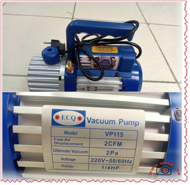
Technical Specifications: The “Heart” of the Pump
Here is the detailed breakdown of what this machine offers.
Feature
Specification
Model
VP115
Voltage / Frequency
220V~50Hz / 60Hz
Free Air Displacement
2 CFM (approx. 50 L/min)
Ultimate Vacuum
5 Pa (0.05 mBar)
Motor Power
1/4 HP
Motor Type
100% Copper Winding (High durability)
Oil Capacity
320 ml
Intake Fitting
1/4″ Flare (Standard SAE)
Dimensions
275 x 122 x 220 mm
Net Weight
~5.3 kg
Application
R134a, R22, R410a, R407c
Comparison: VP115 (Single Stage) vs. Dual Stage Pumps
When you are deciding between a single-stage pump like this and a more expensive dual-stage unit, it helps to see the difference clearly.
Characteristic
VP115 (Single Stage)
Typical Dual Stage (e.g., 2VP-2)
Verdict
Vacuum Depth
5 Pa (Good)
0.3 Pa (Excellent)
Single stage is fine for standard repairs; Dual is for deep-freeze/scientific work.
Weight
~5 kg (Light)
~10 kg (Heavy)
VP115 is much easier to carry to rooftops.
Price
Affordable
Expensive
VP115 offers better ROI for general repairs.
Maintenance
Simple Oil Change
Complex
Single stage is more forgiving with dirty oil.
Performance Analysis: Speed vs. Quality
Let’s compare how this pump performs against other common sizes when evacuating a standard 12,000 BTU Split AC.
Pump Size
Time to 500 Microns
Risk of Freezing Moisture
Best Use Case
1 CFM (Small)
45+ Minutes
Low
Very small fridges only.
2 CFM (VP115)
20-25 Minutes
Balanced
Residential AC & Fridges.
6 CFM (Large)
5-8 Minutes
High (if not careful)
Commercial chillers / Large VRF.
Pro Tip: Always use a micron gauge. The sound of the pump changing pitch is a good sign, but it is not a measurement!
Maintenance & Troubleshooting
To keep your VP115 running for years, follow this simple maintenance schedule.
Symptom
Probable Cause
Solution
Poor Vacuum
Dirty or low oil
Drain oil while warm and refill with fresh vacuum oil.
Oil Mist at Exhaust
Normal operation
This is normal when pumping large amounts of air at the start.
Pump Overheating
Low voltage or blocked fan
Check your extension cord gauge and clean the fan cover.
Hard Start
Cold weather
Warm up the oil or open the inlet port briefly to relieve pressure.
Discover the ECQ Vacuum Pump VP115 (2 CFM, 1/4 HP). Perfect for HVAC technicians and artisans. Full specs, maintenance tips, and comparisons for R134a/R410a systems.
The ECQ Vacuum Pump VP115 is the ideal tool for the artisan bricoleur. With 2 CFM displacement and a durable 1/4 HP motor, it perfectly balances portability and power for residential AC and fridge repairs. This guide covers specifications, maintenance, and why 100% copper winding matters for your daily work.
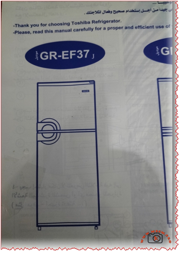
SEO Title (60 characters max): “Toshiba GR-EF37 350L No-Frost Refrigerator | A-Class Energy Efficient”
Meta Description (160 characters max): “Discover the Toshiba GR-EF37 350L no-frost refrigerator with platinum deodorizer, eco-friendly R600a refrigerant, and 10-year compressor warranty. Perfect for large families.”
Excerpt (55 words): “The Toshiba GR-EF37 is a premium 350-liter no-frost refrigerator featuring advanced cooling technology, platinum deodorizer filtration, and exceptional energy efficiency. With dual cooling zones, R600a eco-friendly refrigerant, and a 10-year compressor warranty, this 2-door model represents excellent value for large households seeking reliable refrigeration.”
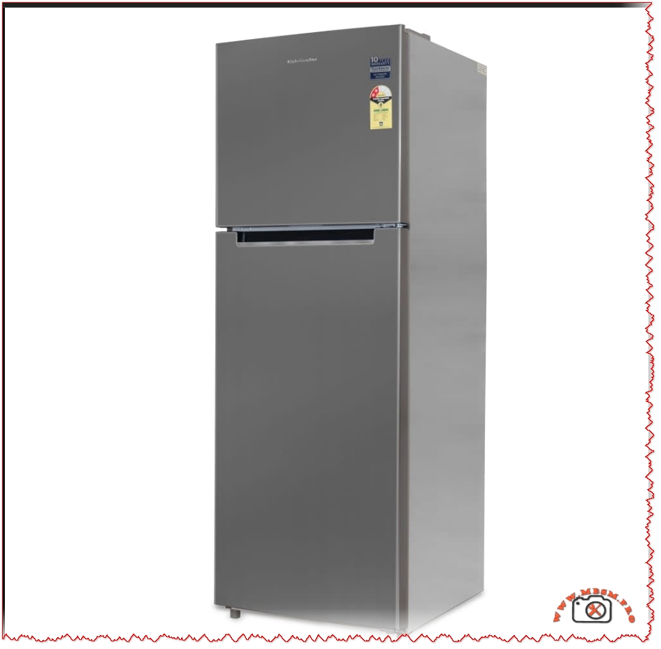
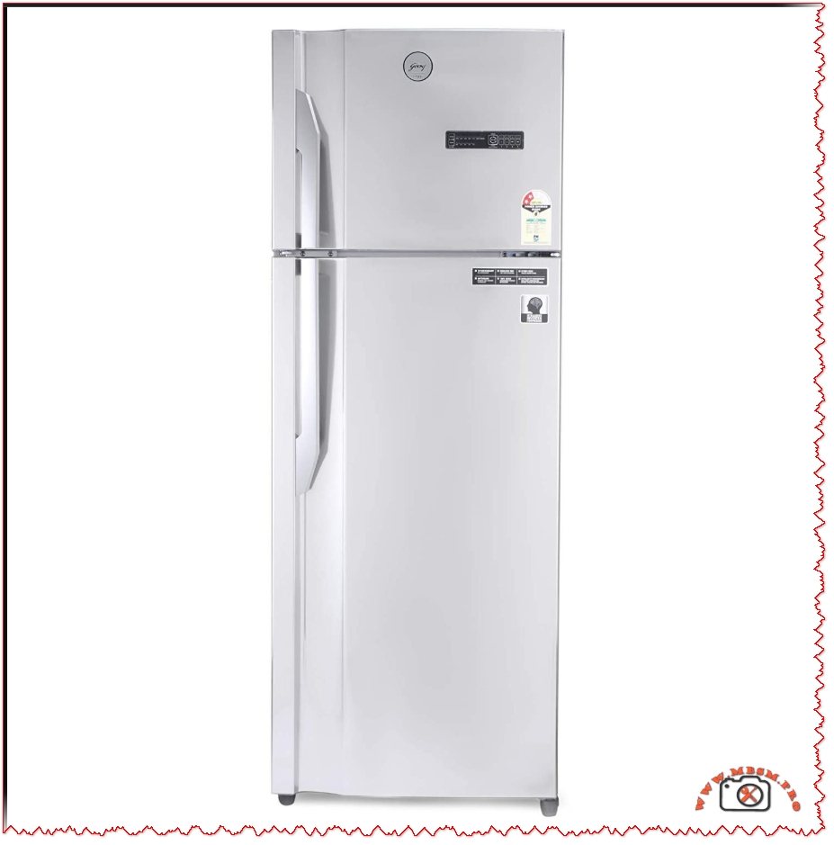
Understanding the Toshiba GR-EF37: A Premium No-Frost Cooling Solution
The Toshiba GR-EF37 stands as one of the market’s most thoughtfully engineered refrigerators for medium to large households. This 350-liter capacity model combines no-frost convenience with exceptional energy efficiency, making it an intelligent choice for families prioritizing both performance and sustainability. The refrigerator has gained particular recognition in Middle Eastern and North African markets due to its reliability and advanced cooling architecture.
What distinguishes the GR-EF37 from conventional refrigeration units is its seamless integration of multiple proprietary technologies designed to preserve food freshness while minimizing operational costs. Unlike traditional refrigerators requiring periodic manual defrosting, this model employs automatic no-frost technology that continuously circulates cold air without ice accumulation, fundamentally transforming the refrigeration experience.
Physical Specifications and Dimensional Overview
The GR-EF37 occupies moderate kitchen space while delivering substantial storage capacity. Understanding these dimensions helps determine kitchen compatibility before purchase:
Specification
Measurement
Details
Total Capacity
350 Liters
Ideal for families of 5-7 members
Width
604 mm (60.4 cm)
Standard kitchen doorway compatible
Depth
681 mm (68.1 cm)
Fits typical kitchen alcoves
Height
1723 mm (172.3 cm)
Eye-level freezer compartment access
Net Weight
64 kg
Requires stable flooring; move with dolly
Gross Weight
71 kg
Includes packaging for transport
Vegetable Drawer
19.3 Liters
Dedicated crisper capacity
Number of Doors
2 Doors
Top freezer, bottom refrigerator layout
Warranty
10 Years (Compressor)
Industry-leading coverage period
These dimensions closely align with competitors like the Samsung RT38DG5A2BBXHL (63 × 173 × 73 cm), demonstrating the GR-EF37’s efficient space utilization without sacrificing capacity.
The no-frost cooling system represents a revolutionary advancement in domestic refrigeration. Rather than allowing ice to accumulate naturally inside the freezer compartment, the Toshiba GR-EF37 employs a fan-assisted circulation mechanism that continuously disperses dehumidified cold air throughout both refrigerator and freezer sections.
How the System Functions:
Traditional frost-accumulating refrigerators experience moisture entering through door openings and from stored food items. This moisture freezes on evaporator coils, progressively reducing cooling efficiency. The GR-EF37 eliminates this problem through compartmentalized evaporator placement and intelligent air routing.
Measurable Performance Advantages:
Research conducted on no-frost refrigeration systems demonstrates significant efficiency improvements. A study comparing thermal performance indicators revealed that no-frost systems maintain 15-20% more consistent temperatures compared to direct-cool alternatives. For food preservation, this consistency proves critical—it prevents fluctuating conditions that accelerate spoilage and reduces freezer burn incidents by up to 40% according to domestic refrigeration analysis.
The system automatically defrosts evaporator coils during compressor idle cycles, directing melted water through drain channels rather than into food storage areas. This automatic defrosting occurs without user intervention, eliminating the inconvenience of removing frozen goods and waiting for ice to thaw—a process that previously consumed 4-6 hours monthly for traditional units.
Energy Efficiency: Understanding the A-Class Rating
The Toshiba GR-EF37 carries the Energy Efficiency Class A designation, representing the highest performance tier in modern appliance ratings. This classification indicates the unit consumes significantly less electricity than comparable capacity refrigerators.
Energy Performance Benchmarking:
Factor
Class A Performance
Class B Comparison
Class C Comparison
Annual Energy Consumption
~320-370 kWh
~420-480 kWh
~520-600 kWh
Monthly Cost (@ $0.12/kWh)
~$3.20-$3.70
~$4.20-$4.80
~$5.20-$6.00
Annual Savings vs Class B
~20-25% less
Baseline
Higher consumption
Monthly Operational Cost
Lowest tier
30% higher
50-60% higher
The Class A rating becomes particularly valuable in regions with high electricity costs. Over a 10-year product lifespan, this efficiency differential translates to approximately $800-1,200 in cumulative energy savings compared to Class B alternatives, effectively subsidizing a significant portion of the refrigerator’s purchase price.
This performance stems directly from the GR-EF37’s inverter-based compressor, which modulates cooling intensity based on internal temperature fluctuations rather than operating at constant capacity. During periods of minimal temperature variance, the compressor reduces power draw substantially, whereas traditional fixed-speed compressors maintain maximum operation regardless of cooling demand.
R600a Refrigerant: Environmental and Performance Advantages
The Toshiba GR-EF37 utilizes R600a (isobutane) refrigerant, an environmentally superior choice compared to the R134a refrigerant used in many competing models. This technical distinction carries both environmental and operational implications.
Researchers analyzing R600a performance in domestic refrigerators observed that “the coefficient of performance was found to be in the higher range compared to R134a, almost 20%-25% better than R134a at constant load conditions.” The practical implication: the GR-EF37 cools food more rapidly while consuming less electrical energy, representing genuine thermodynamic superiority rather than incremental improvement.
Environmental Impact Significance:
R600a carries negligible global warming potential (GWP of 3-4 versus R134a’s 1,450), making it climatically preferable despite being hydrocarbon-based. Modern compressors designed for R600a incorporate precision engineering that safely contains the refrigerant, and decades of Asian-market deployment demonstrates reliable safety profiles. The GR-EF37’s manufacturing process utilizes cyclopentane foam insulation rather than CFC-based alternatives, further minimizing the unit’s environmental footprint.
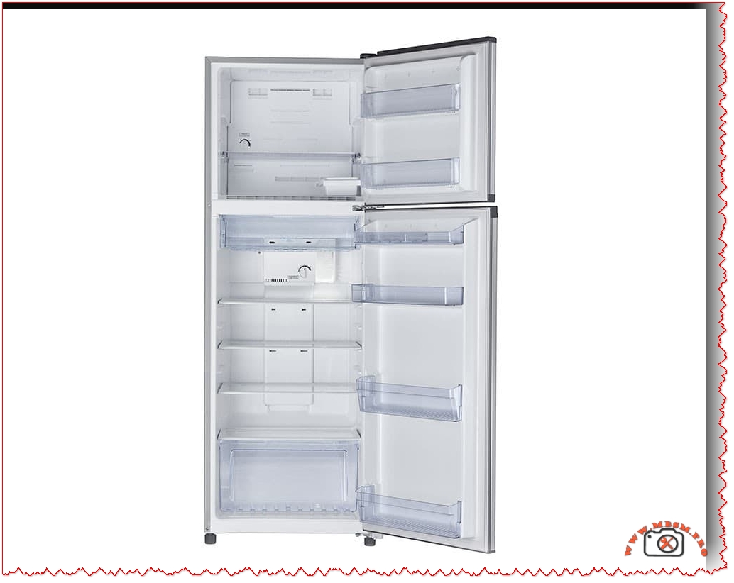
Design Features: Platinum Deodorizer and Interior Architecture
The GR-EF37 incorporates specialized features addressing common refrigeration challenges that impact daily user experience:
Platinum Deodorizer Filter System:
This proprietary filtration mechanism neutralizes odor molecules through activated carbon enriched with platinum compounds. Unlike basic carbon filters requiring quarterly replacement, the platinum formulation extends operational life to 12-18 months while providing superior odor capture across diverse food categories. The filter addresses cross-contamination issues inherent in shared cooling spaces—onion scent no longer permeates dairy products, and strong spices remain compartmentalized.
Interior Shelving and Food Organization:
Hardy glass shelves with reinforced tempering technology support up to 150kg distributed weight, enabling storage of bulk purchases and large containers without deformation. The gentle slopes prevent liquid spillage from flowing toward door-mounted compartments, and the translucent construction permits rapid visual inventory assessment without opening doors—reducing cold air loss and maintaining energy efficiency.
Vegetable and Fruit Preservation Drawer:
The dedicated 19.3-liter crisper drawer maintains enhanced humidity levels optimal for produce storage, extending vegetable freshness by 5-7 days compared to standard refrigerator sections. Humidity control prevents moisture loss that causes wilting while avoiding condensation that promotes bacterial growth.
Comparative Market Analysis: How the GR-EF37 Positions Against Competitors
Understanding the GR-EF37’s competitive positioning provides context for purchase decisions:
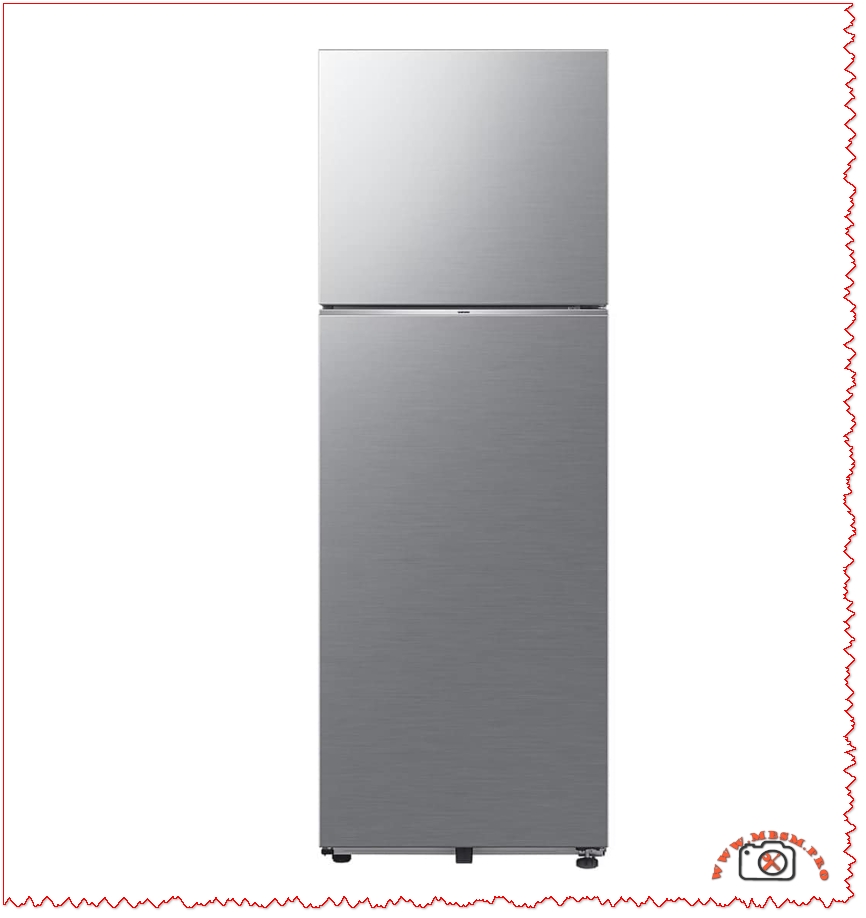
Toshiba GR-EF37 vs. Samsung RT38DG5A2BBXHL (350L 2-Star):
Attribute
Toshiba GR-EF37
Samsung RT38DG5A2BBXHL
Winner/Comment
Energy Class
A (Superior)
2-Star (~Class B equivalent)
Toshiba: 20-25% more efficient
Annual Energy Cost
~$38-45
~$50-60
Toshiba saves $120-150/year
Compressor Warranty
10 Years
10 Years
Equal coverage
Standard Warranty
1 Year implied
1 Year
Equivalent
Smart Features
Basic controls
Wi-Fi SmartThings enabled
Samsung offers connectivity
Cooling Technology
No-Frost (Automatic)
Twin Cooling Plus (Auto)
Both prevent manual defrosting
Dimensions
604×681×1723mm
630×732×1780mm
Toshiba slightly more compact
Price Point
Mid-range (~$400-500)
Premium (~$600-800)
Toshiba offers better value
Best For
Budget-conscious buyers
Tech-integrated smart homes
Different use cases
The Samsung model appeals to users prioritizing IoT integration and smartphone connectivity, while the Toshiba serves cost-conscious buyers seeking reliability and energy economy.
Toshiba GR-EF37 vs. LG Refrigerators (350L Category):
LG’s competing models like the GL-T502FRS2 emphasize multi-air flow systems and premium finish options but typically carry higher energy classifications (2-3 Star ratings) and reduced warranty coverage compared to the GR-EF37’s 10-year compressor protection. For users prioritizing longevity and operational economy over smart-home integration, the Toshiba represents superior total-cost-of-ownership value.
Installation and Operational Considerations
Proper Placement Fundamentals:
The GR-EF37 requires minimum 10cm clearance on both sides and rear to permit adequate heat dissipation from compressor-mounted condenser coils. Placement adjacent to ovens or direct sunlight significantly reduces efficiency and increases compressor cycling frequency. Optimal locations feature ambient temperatures between 10°C-32°C; tropical climates require ensuring air-conditioning maintains surrounding temperature within this range.
Electrical Requirements:
The unit operates on standard 220-240V AC, 50Hz power supply common in Middle Eastern and European markets. Stabilizer-free operation is supported (confirmed stabilizer-free on competitive models), though voltage stabilizers remain recommended in regions experiencing fluctuations exceeding ±10V. A dedicated circuit prevents voltage sags that could damage compressor motor windings.
First-Time Operation Protocol:
Upon delivery, allow the unit to stand upright for minimum 4-6 hours before initial power connection. This permits refrigerant redistribution in the sealed system after potential tilting during transport. Clean interior surfaces with mild soap solution before loading food items.
Monthly: Inspect door seals for gaps; wipe rubber gaskets with mild detergent to prevent mold growth
Quarterly: Clean condenser coils located beneath or behind unit using brush; debris restricts heat dissipation
Semi-Annual: Defrost and clean interior crisper drawers; remove platinum deodorizer filter and rinse under running water
Annual: Check temperature using independent thermometer in both compartments; adjust controls if readings deviate >2°C
Troubleshooting Common Issues:
Should the compressor run continuously without reaching set temperature, verify that door seals close completely (misalignment reduces cooling efficiency by 15-30%). If frost accumulates despite no-frost technology, the automatic defrost timer may require service—contact authorized Toshiba technicians rather than attempting internal repairs that could breach system integrity.
Professional Recommendations and Conclusion
The Toshiba GR-EF37 represents a mature refrigeration solution balancing energy efficiency, environmental responsibility, and practical user functionality. Its 10-year compressor warranty signals manufacturer confidence in long-term reliability, while the Class A energy rating ensures operational costs remain economically favorable across extended product lifespan.
This model suits buyers seeking:
Maximum energy economy in mid-capacity refrigeration
Environmentally conscious appliance selection
Proven reliability over cutting-edge smart features
Strong warranty protection and manufacturer support
For regions throughout North Africa, the Middle East, and countries utilizing 220-240V/50Hz electrical standards, the GR-EF37 delivers consistent value and performance. Its no-frost architecture eliminates refrigeration’s most persistent inconvenience—manual defrosting—while R600a refrigerant technology provides thermodynamic advantages that mainstream manufacturers continue adopting as environmental regulations tighten globally.
Investment in this refrigerator represents commitment to both household food safety and responsible resource consumption, delivering measurable energy savings that accumulate meaningfully across the unit’s intended 12-15 year operational lifespan.