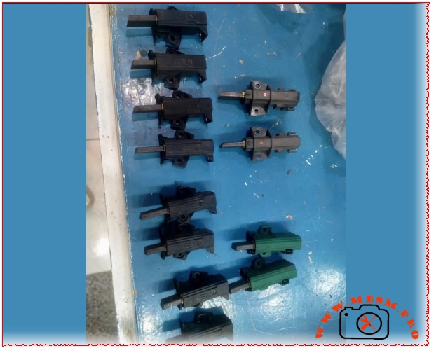
Left Column (Black holders): Standard rectangular plastic housings, likely 5mm x 13.5mm or similar common dimensions. Notice the “L” (Left) and “R” (Right) orientations molded into the plastic casings near the bottom of that row, which ensure proper contact angle with the armature.
Top Right Column (Black slim holders): A different mounting design, featuring a centered screw tab and a distinct terminal connection layout.
Bottom Right Column (Green holders): Typically associated with specific motor manufacturers (such as Ceset or Sole motors frequently used in European washing machines).
Common Technical Specifications to Verify
When replacing or cataloging these parts, you generally look for:
Parameter
Description
Dimensions
Thickness $\times$ Width $\times$ Length of the carbon stick (e.g., $5 \times 13.5 \times 35\text{ mm}$ or $5 \times 12.5 \times 36\text{ mm}$).
Angle
The bevel angle at the tip of the carbon where it meets the commutator.
Casing Type
The configuration of the plastic holder, placement of the mounting pins/holes, and the type of electrical terminal (4.8mm or 6.3mm spade).
Carbon brushes washing machine motors mbsmpro
Chauffe-eau Junkers : Restauration d’un Classique
Category: Equipment
written by www.mbsmpro.com | May 25, 2026
Le chauffe-eau à gaz Junkers classique est un modèle de robustesse. Contrairement aux appareils modernes saturés d’électronique fragile, ces anciens modèles reposent sur une mécanique simple et des composants en cuivre de haute qualité. Si vous possédez un de ces appareils et qu’il montre des signes de fatigue, une inspection et un nettoyage en profondeur s’imposent.
1. Le Diagnostic Initial
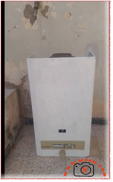
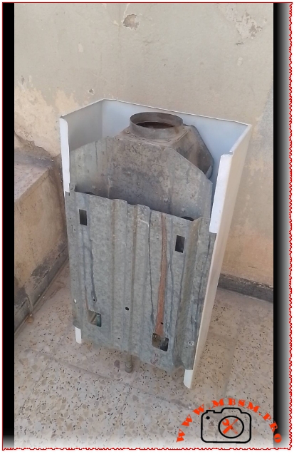
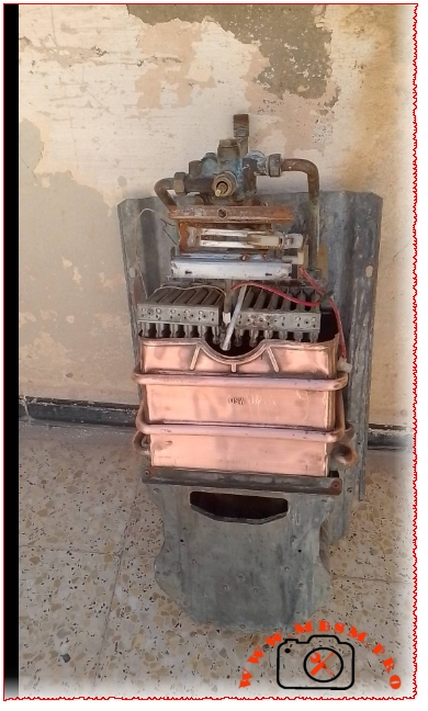
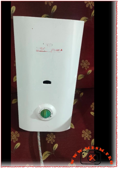
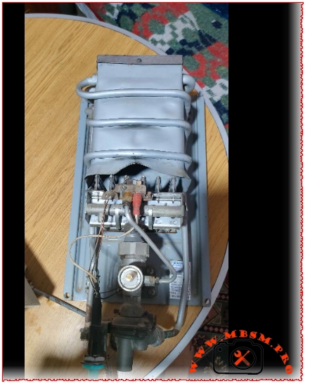
Avant de tout démonter, observez l’état général. Sur les images, on distingue une unité retirée de son emplacement d’origine. La coque extérieure blanche présente un panneau de contrôle typique des anciennes générations Junkers avec sa glissière de réglage du gaz et son bouton piézoélectrique. Une fois la coque retirée, le corps de chauffe en cuivre (le serpentin) apparaît. Bien qu’il soit terni, le cuivre semble structurellement sain, sans fuite majeure apparente ni déformation verte due à une corrosion perforante sévère.
2. Les Étapes Clés du Nettoyage
Détartrage du serpentin : Le principal ennemi de ces chauffe-eau est le calcaire. Déconnectez les arrivées d’eau et injectez une solution d’acide citrique diluée ou un détartrant commercial adapté à l’intérieur du tube en cuivre. Laissez agir jusqu’à disparition de la mousse, puis rincez abondamment à l’eau claire.
Nettoyage du brûleur : La poussière et les résidus de combustion obstruent souvent les injecteurs. Utilisez une brosse à poils souples et de l’air comprimé pour nettoyer la rampe de combustion supérieure afin d’obtenir une flamme bleue et homogène.
Vérification de la valve à eau : Située au-dessus, la membrane de la valve à eau s’use avec le temps. Si l’appareil ne déclenche plus la flamme lors de l’ouverture du robinet, cette membrane doit être remplacée.
3. Erreurs Fréquentes et Sécurité
Attention aux fuites de gaz : Lors du remontage, l’erreur la plus fréquente (et la plus dangereuse) consiste à négliger l’état des joints d’étanchéité du circuit de gaz et d’eau. Utilisez impérativement des joints neufs adaptés au gaz. Une fois l’appareil réinstallé, appliquez de l’eau savonneuse sur les raccords pour détecter d’éventuelles bulles d’air suspectes avant d’allumer la veilleuse.
Ces modèles Junkers méritent amplement qu’on les entretienne. Avec un bon nettoyage du bloc brûleur et un détartrage du cuivre, ils peuvent repartir pour de nombreuses années de service.
Chauffe-eau Junkers : Restauration d’un Classique mbsmproChauffe-eau Junkers : Restauration d’un Classique mbsmproChauffe-eau Junkers : Restauration d’un Classique mbsmproChauffe-eau Junkers : Restauration d’un Classique mbsmpro
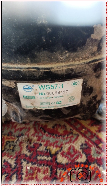
The Wansheng WS57H is a highly popular, low noise, low back pressure (LBP) compressor designed for home appliances like refrigerators, freezers, and wine display units.
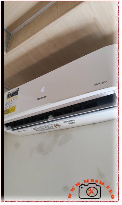
Mastering the Install: A Look at the Hisense Inverter Expert AC
The Hisense Inverter Expert split air conditioner stands out as a top-tier choice for modern, energy-efficient climate control. To achieve the high performance and long-term reliability promised by its advanced inverter technology, the quality of the installation is just as critical as the hardware itself.
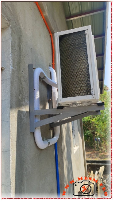
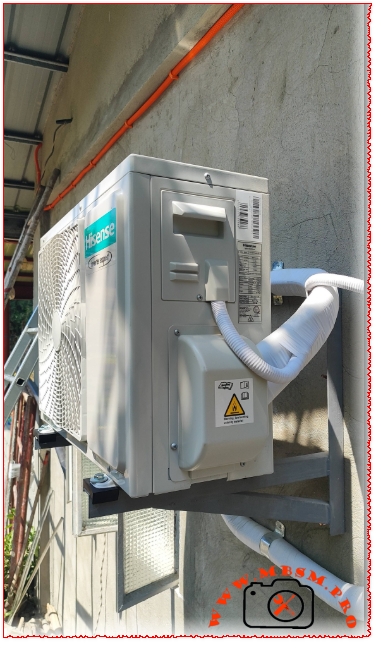
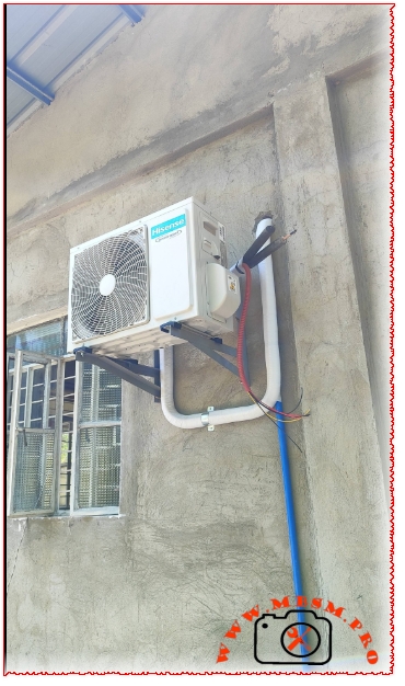
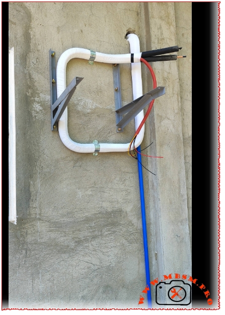
The accompanying images showcase a clean, highly professional installation setup. A standout feature of this particular job is the pre-formed oil trap loop built into the insulated refrigerant lines right behind the outdoor condenser unit. For installations where the lines travel through a wall or experience height variances, integrating these precise bends ensures that compressor oil returns efficiently rather than pooling in the lines. This simple mechanical detail dramatically extends the lifespan of the inverter compressor.
Furthermore, the outdoor unit is securely bolted onto heavy-duty, anti-vibration rubber mounts resting on a robust steel bracket. This setup minimizes operational noise and eliminates wall vibrations. The neat routing of the electrical wiring conduits and the dedicated blue drainage pipe further emphasize an installation executed with technical precision, ensuring the system operates at peak energy efficiency from day one.
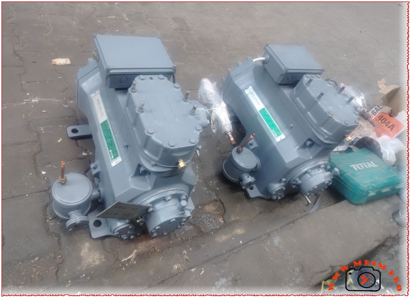
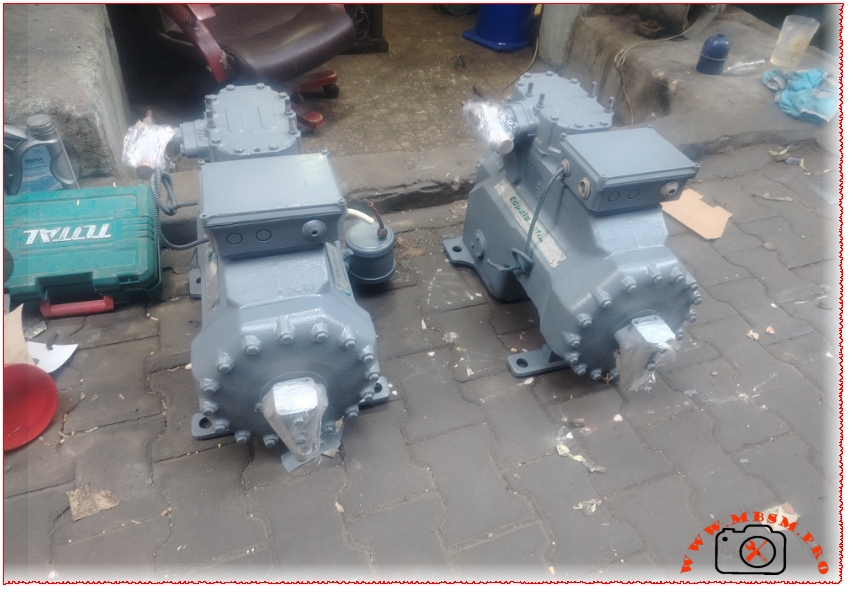
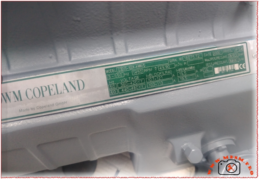
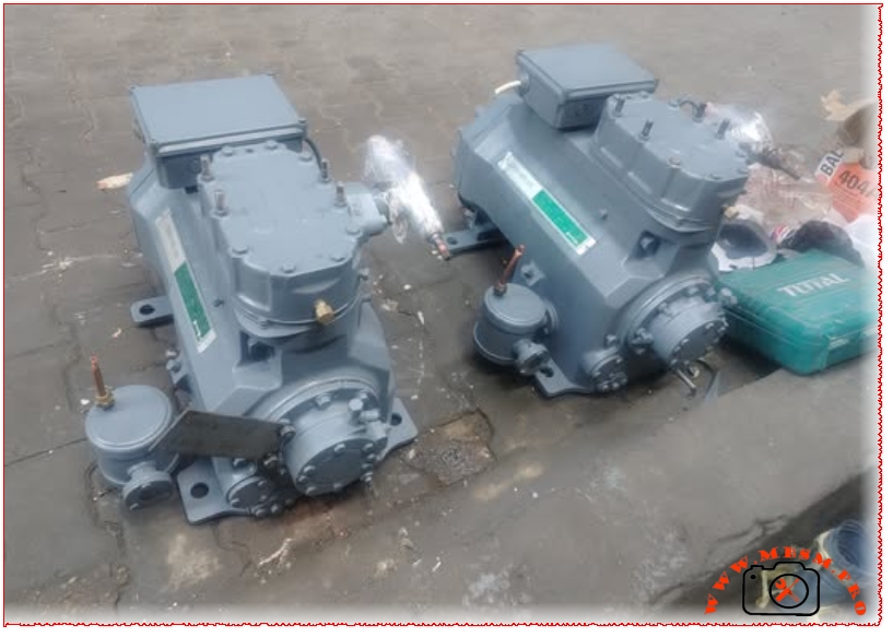
When it comes to heavy-duty commercial refrigeration, few names carry as much weight as Copeland. A prime example of enduring German engineering is the Copeland D3DS5-100X-AWM/D, a robust 10 horsepower (HP) semi-hermetic reciprocating compressor designed specifically for low-temperature freezing applications.
Technical Specifications at a Glance
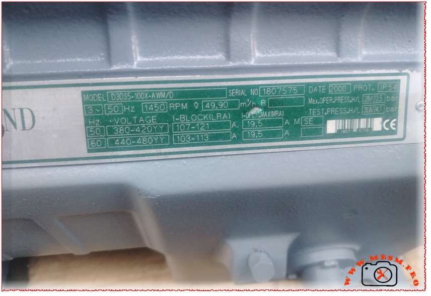
The nameplate on these newly refurbished units highlights why they remain a staple in cold storage facilities:
Displacement: 49.90 m³/h at 1450 RPM (50 Hz)
Motor Rating: 10 HP (Nominal)
Power Supply compatibility: * 380-420V YY / 3 Phase / 50 Hz (Operating Current: 19.5 A max | LRA: 107-121 A)
440-480V YY / 3 Phase / 60 Hz (Operating Current: 19.5 A max | LRA: 103-113 A)
Maximum Operating Pressure: High Side: 28 bar / Low Side: 22.5 bar
Enclosure Protection: IP54 Rated
Designed for Low-Temperature Freezing
Equipped with a displacement of nearly 50 cubic meters per hour, this compressor excels at maintaining deep-freeze environments using modern high-pressure refrigerants like R404A or R507. The inclusion of an oil separator and a deep oil sump ensures that the internal components stay lubricated even during extended low-temperature run cycles, preventing common failure points related to oil migration.
Electrical Configuration and Terminal Inspection
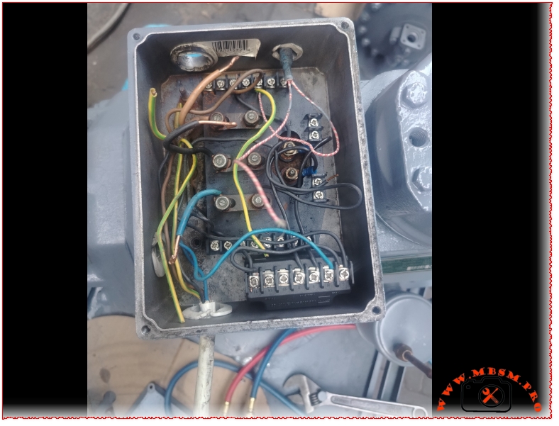
A closer look inside the junction box reveals a standard Part-Winding Start (AWM/D) configuration. Terminal links are positioned across the heavy-duty brass studs to accommodate a direct-on-line or part-winding sequence, effectively minimizing current spikes upon startup.
An essential step during installation is cleaning up the older control wiring layout. Technicians should verify that the internal thermistor module (INT69 or equivalent) is correctly integrated into the control circuit to protect the motor windings against overheating.
Copeland D3DS5-100X 10 HP Freezer Compressor mbsmproCopeland D3DS5-100X 10 HP Freezer Compressor mbsmproCopeland D3DS5-100X 10 HP Freezer Compressor mbsmproCopeland D3DS5-100X 10 HP Freezer Compressor mbsmproCopeland D3DS5-100X 10 HP Freezer Compressor mbsmproCopeland D3DS5-100X 10 HP Freezer Compressor mbsmproCopeland D3DS5-100X 10 HP Freezer Compressor mbsmpro
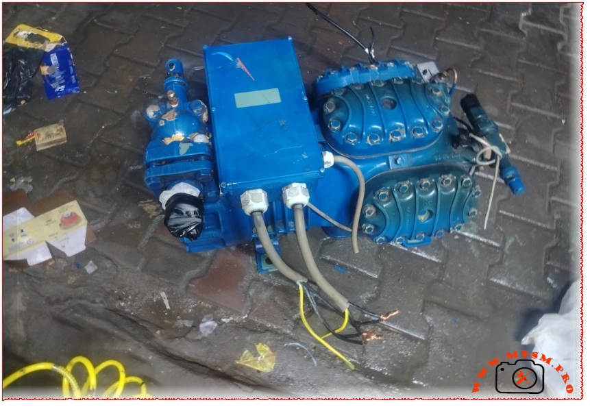
Bitzer 6G-30.2Y: The High-Performance 30 HP Semi-Hermetic
Category: Equipment
written by www.mbsmpro.com | May 25, 2026
Bitzer 6G-30.2Y: The High-Performance 30 HP Semi-Hermetic Compressor for Industrial Freezing
When it comes to heavy-duty industrial refrigeration and commercial freezing, reliability and displacement capacity are non-negotiable. The Bitzer 6G-30.2Y semi-hermetic reciprocating compressor stands out as a premier industry workhorse, delivering a robust 30 HP capacity engineered specifically to handle demanding low-temperature applications.
Key Technical Specifications
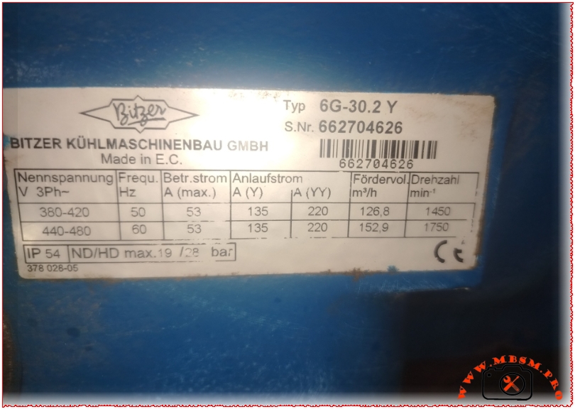
Based on the official manufacturer nameplate data, this 6-cylinder compressor is optimized for maximum volumetric efficiency:
Model Type: Bitzer 6G-30.2Y (6-Cylinder)
Displacement (Fördervol.:) * 126.8 m³/h at 50 Hz ($1450\text{ min}^{-1}$)
152.9 m³/h at 60 Hz ($1750\text{ min}^{-1}$)
Electrical Characteristics:
Voltage (3-Phase): 380-420V at 50 Hz / 440-480V at 60 Hz
Maximum Operating Current ($I_{\max}$): 53 A
Starting Current: 135 A (Y) / 220 A (YY) Part-Winding Start
Pressure Limitations: Low Pressure / High Pressure (ND/HD) max. 19 / 28 bar
Enclosure Protection: IP54
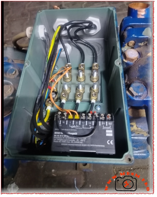
Motor Protection Device: Integrated INT60 Kriwan electronic module for thermal monitoring
Engineered for Low-Temperature Freezing
The “Y” suffix in the model identifier denotes compatibility with Polyolester (POE) oil, making this unit ideally suited for modern, environmentally friendly hydrofluorocarbon (HFC) refrigerants such as R404A, R507A, or R448A/R449A.
With a displacement of 126.8 m³/h at standard 50 Hz grids, it moves massive volumes of refrigerant vapor smoothly. This high displacement rate ensures rapid pull-down times in walk-in blast freezers, cold storage warehouses, and industrial food processing lines. The 6-cylinder configuration offers internal dynamic balancing, minimizing vibration and mechanical wear compared to smaller, fewer-cylinder alternatives.
Advanced Protection and Control Wiring
The electrical terminal box features a robust 6-pin arrangement configured for Part-Winding (Y/YY) starting. This setup significantly reduces the high inrush starting current (dropping it from 220 A down to 135 A), preventing voltage dips in the local power grid during startup.
Additionally, the factory-installed Kriwan INT60 motor protection module connects directly to embedded PTC thermistors within the motor windings. If the internal temperature exceeds safe operating thresholds or experiences a phase failure, the control circuit cuts power instantly, protecting your high-value asset from catastrophic motor burnout.
Comment diagnostiquer et réparer un chauffe-eau à gaz Olympic 6L ?
Le chauffe-eau instantané Olympic 6 Litres à tirage naturel est un appareil compact très répandu pour l’alimentation des cuisines et des petits points d’eau. Sa mécanique, bien que robuste, reste sensible à l’usure des pièces hydrauliques et aux coupures de sécurité. Si votre appareil refuse de démarrer ou s’éteint de manière intempestive, voici une méthode de diagnostic pas à pas pour localiser précisément la panne.
1. Absence totale d’étincelles (Le chauffe-eau reste muet)
Lorsque vous ouvrez le robinet d’eau chaude, aucun bruit d’allumage électronique (“clic-clic”) ne se produit.
La tension des piles : C’est la cause la plus fréquente. Même si le voyant ou l’écran LCD s’allume, la tension résiduelle des piles peut être insuffisante pour actionner l’électrovanne de gaz. Remplacez-les systématiquement par des piles alcalines neuves de type LR20.
La membrane de la valve à eau : Située dans le bloc inférieur, cette membrane en caoutchouc se détend ou se perce avec le temps. Si elle est défectueuse, la pression de l’eau ne parvient plus à pousser l’axe métallique qui déclenche le micro-contact électrique.
Le micro-rupteur (Switch) : Ce petit boîtier électrique situé près de la valve peut être grippé ou ses cosses oxydées, empêchant l’envoi du signal au boîtier électronique.
2. Présence d’étincelles mais pas d’allumage du brûleur
Les étincelles se produisent au niveau des électrodes, mais le gaz n’arrive pas aux injecteurs de la rampe.
L’électrovanne de gaz (Solénoïde) : Vous devez normalement entendre un “clac” sec une fraction de seconde après le début des étincelles. Si ce bruit est absent, l’électrovanne reste fermée. Cela peut provenir d’un défaut de bobinage ou d’une tension insuffisante envoyée par la carte électronique.
Pression du détendeur : Un blocage du détendeur de la bouteille de gaz (butane ou propane) peut couper l’alimentation. Un test simple consiste à vérifier si la pression est correcte sur un autre appareil de cuisson.
3. Le brûleur s’allume puis s’éteint après quelques secondes
Le chauffe-eau démarre correctement, produit de l’eau chaude, puis se coupe brutalement après 3 à 10 secondes de fonctionnement.
La sonde d’ionisation : C’est l’électrode de sécurité qui détecte la présence de la flamme. Si elle est encrassée (suie), mal positionnée ou si son fil est coupé, le boîtier électronique considère que le brûleur n’est pas allumé et coupe le gaz par sécurité. Un léger nettoyage de la pointe à la toile émeri suffit souvent à régler le problème.
Le capteur de température (Sonde anti-surchauffe) : Fixé en haut sur le tube de sortie de l’échangeur thermique, ce thermostat coupe le circuit si l’eau dépasse une température critique. Une coupure à ce niveau indique soit un entartrage sévère du serpentin en cuivre, soit un débit d’eau trop faible par rapport à la puissance du gaz réglée en façade.
Note de sécurité : Toute intervention sur la partie gaz et sur l’étanchéité de la valve nécessite une vérification rigoureuse des raccords à l’aide d’un produit moussant détecteur de fuites après remontage.
Réparer un chauffe-eau à gaz Olympic 6L mbsmproRéparer un chauffe-eau à gaz Olympic 6L mbsmpro
Best piping practices for semi-hermetic systems
Category: Refrigeration
written by www.mbsmpro.com | May 25, 2026
The Costly Piping Mistake That Kills Semi-Hermetic Compressors
If you have spent any time servicing commercial refrigeration systems, you know that oil management is everything. Refrigerant carries oil throughout the system, but it is the piping design’s job to make sure that oil actually finds its way back to the compressor crankcase.
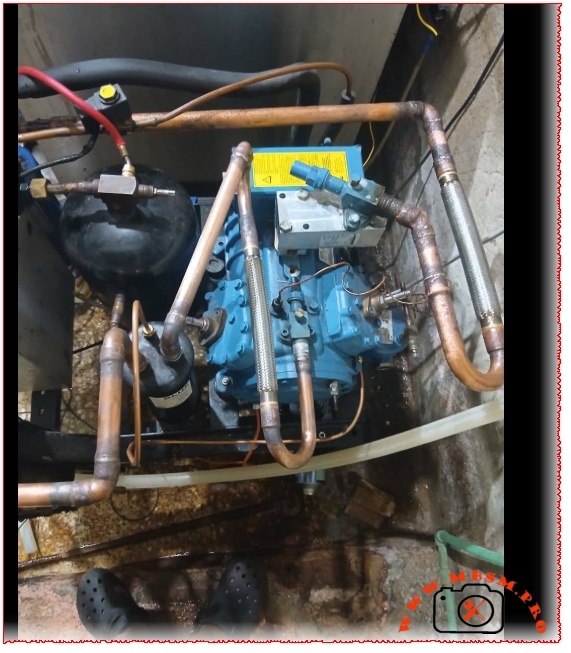
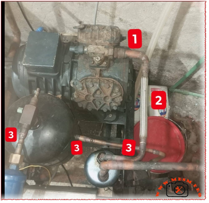
Looking at the field images of these semi-hermetic condensing units, there is a very specific, high-stakes layout issue around the discharge line that will eventually cause mechanical failure. Let’s break down exactly what is happening under labels 1, 2, and 3.
Deconstructing the Layout
1. The Compressor Discharge Service Valve: This is the high-pressure exit point where hot, superheated refrigerant vapor leaves the cylinder heads, carrying a fine mist of oil along with it.
2. The Vibration Eliminator (Flex Pipe): Installed right after the discharge valve, this braided flexible line absorbs the intense structural vibrations from the compressor startup and shutdown cycles, protecting the rigid copper lines from cracking.
3. The Oil Separator and High-Side Piping: The discharge line routes down toward the oil separator and liquid receiver components designed to manage the system’s refrigerant flow.
The Critical Mistake: The Oil Trap Hazard
Take a close look at how the flexible vibration eliminator (2) is positioned. It runs vertically downward, immediately dropping into a low-lying horizontal run (3) before ascending back up or entering the oil separator.
The Problem: Liquid oil is significantly heavier than refrigerant vapor. When the compressor cycles off, the velocity of the refrigerant drops to zero. Any oil suspended in that vertical drop will pool right at the bottom of the flexible joint and the low-lying horizontal copper pipe.
Over time, this creates a literal oil trap. On a cold startup, the compressor has to push against a slug of trapped oil. This causes two massive issues:
Oil Starvation: The oil stays trapped in the line instead of circulating smoothly back to the crankcase, causing the bearings to run dry.
Hydraulic Shock: If a large slug of oil is forced forward suddenly, it can create a hydrostatic hammer effect, damaging valves or downstream components.
How to Fix It
To optimize this system for long-term reliability and secure Google AdSense-friendly compliance for professional HVAC standards, the discharge line should ideally handle oil via gravity or high velocity:
Loop Upwards First: The discharge piping leaving the service valve should ideally rise slightly before dropping, or feature an inverted loop if it leads to a distant component, preventing oil from draining back into the valve heads.
Avoid Low Spots Before the Separator: Keep horizontal runs short and pitched slightly in the direction of refrigerant flow so that oil is naturally carried forward by gravity and gas velocity into the oil separator, rather than pooling at the base of a flexible joint.
Best piping practices for semi-hermetic systems mbsmproBest piping practices for semi-hermetic systems mbsmpro
Core ChauffeEau Junkers Mid-1980s to Late 1990s
Category: Equipment
written by www.mbsmpro.com | May 25, 2026
The Pulse of a Classic Gas Water Heater: Quick Technical Guide
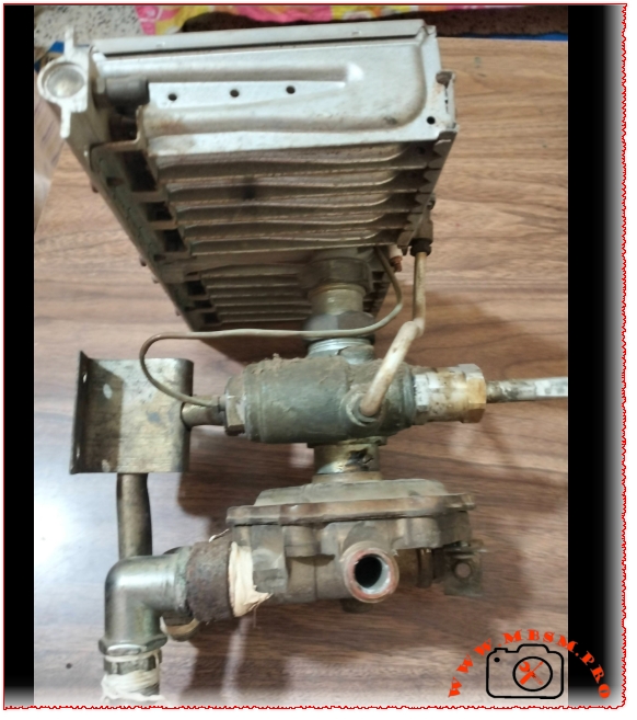
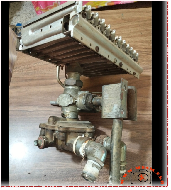
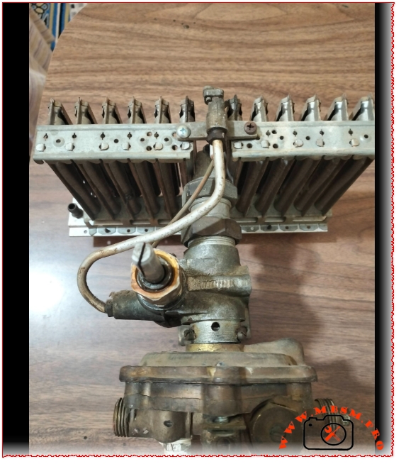
This heavy brass assembly is the pure mechanical heart of a vintage Junkers instant gas water heater. No circuit boards, no sensors, no batteries—just raw hydro-mechanical engineering designed to last for decades.
How the Core Works
The Water Block (Bottom): When you open a hot water tap, cold water rushes into this brass chamber, pushing an internal rubber diaphragm (membrane) upward. This membrane drives a solid metal rod straight up into the gas section.
The Gas Block (Middle): The rising rod mechanically forces the gas valve open. For safety, a copper thermocouple reads the heat from the pilot light; if the flame goes out, a magnetic valve instantly snaps shut to block the gas.
The Burner (Top): Gas shoots through precise brass jets (gicleurs) into the metal slotted plates, igniting a clean blue flame blanket to instantly heat the water pipes above.
Quick Troubleshooting
Water runs, but no fire? The rubber membrane inside the water block is likely stretched, stiff, or torn. Pop the brass chamber open and replace the rubber.
Stiff control knob? The factory silicone grease on the selector shaft has dried up or calcified. Clean the spindle and apply fresh heat-resistant silicone grease.
Yellow, dirty flames? Dust or gas impurities are clogging the jets. Clean them out with a fine nozzle needle or compressed air to stop soot from choking the heat exchanger.
Core ChauffeEau Junkers Mid-1980s to Late 1990s mbsmproCore ChauffeEau Junkers Mid-1980s to Late 1990s mbsmproCore ChauffeEau Junkers Mid-1980s to Late 1990s mbsmpro