Not recommended! R410A has very high pressure. R407C has much lower pressure. This means the compressor is designed for completely different conditions.
Difference in thermal performance: Cooling and condensation are different. If you use the same system: Cooling weakens, pressure becomes unbalanced, and the system may overheat or be damaged.
Oil: R410A often uses POE oil. R407C also uses POE, but: The problem isn’t just the oil, but the entire system design.
Pipe and capillary/TXV: R410A requires different capillary/détendeur setup. R407C has different expansion and glide behavior.
Details of refrigerant R134a
Category: Refrigeration
written by www.mbsmpro.com | May 24, 2026
How to decode “R134a” like a pro
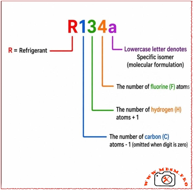
The number isn’t random. It follows a simple system called the Ashrae refrigeration numbering scheme.
Here’s the formula hidden in the image:
R = Refrigerant Then the digits mean:
First digit = Number of carbon (C) atoms – 1
Second digit = Number of hydrogen (H) atoms + 1
Third digit = Number of fluorine (F) atoms
Lowercase letter (like “a”) = Specific isomer (same atoms, different arrangement)
Let’s test it on R134a
Break it down:
R = Refrigerant
1 = Carbon atoms? → Number is 1, so carbon atoms = 1 + 1 = 2 carbon atoms (C₂)
3 = Hydrogen atoms? → Number is 3, so hydrogen atoms = 3 – 1 = 2 hydrogen atoms (H₂)
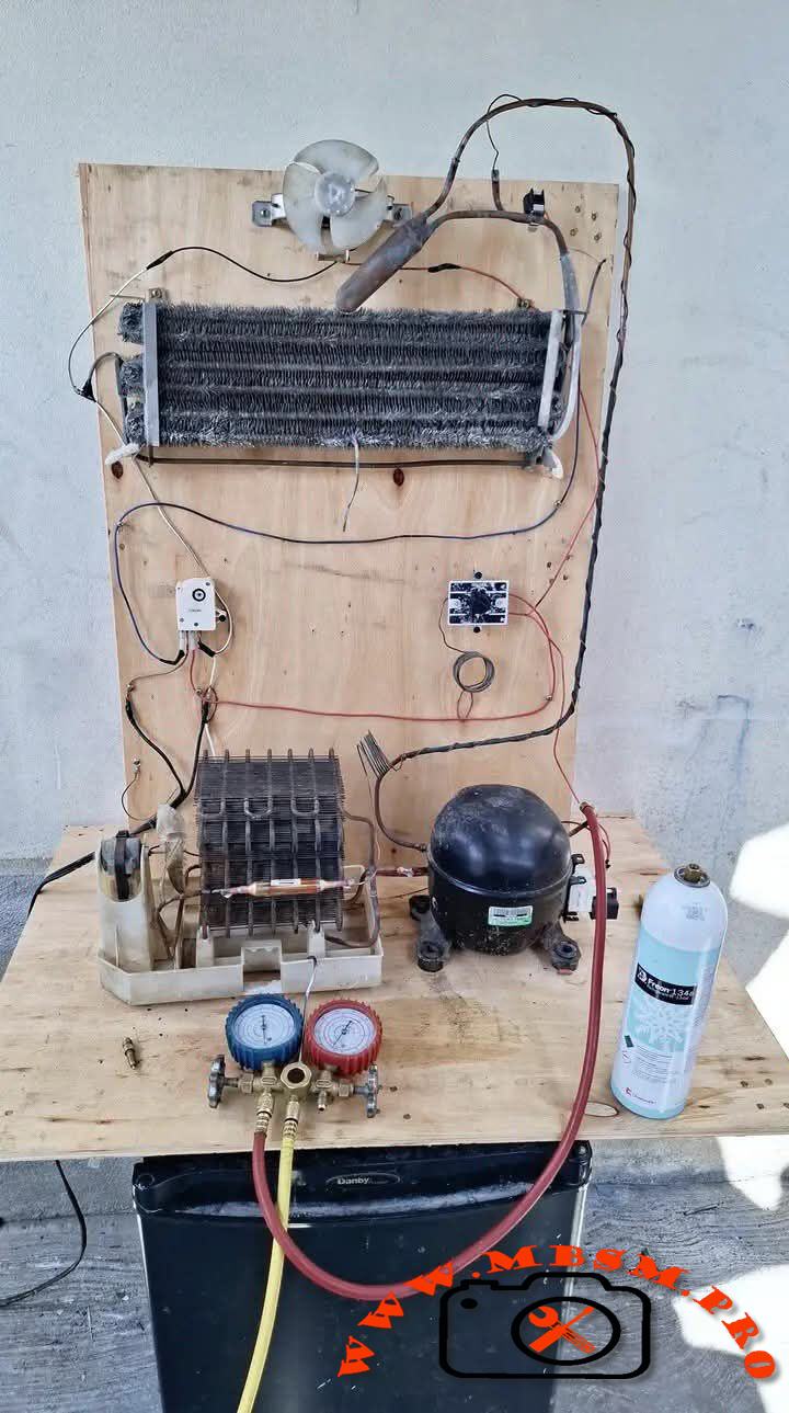
The electrical circuit for a timer-based steam refrigerator is an interesting one
Category: Refrigeration
written by www.mbsmpro.com | May 24, 2026
The electrical circuit of a timer-based steam refrigerator is a clever and ingenious circuit because it divides the operation into two essential phases that never overlap: the cooling phase and the defrosting phase.
First, let’s explain the function of each component, followed by a detailed explanation of how to connect the circuit.
First: Functions of the Electrical Components
Defrost Timer: This is the brain of the circuit. It contains a small motor and four terminals (often numbered 1, 2, 3, and 4). Its function is to switch between cooling mode (approximately 6 to 8 hours) and defrosting mode (approximately 20 to 25 minutes).
Thermostat: This is a thermal switch that controls the refrigerator’s on/off operation based on the temperature inside the refrigerator compartment. This protects food and saves energy.
Relay: This relay is responsible for supplying the starting current to the compressor’s start windings and then disconnecting them, allowing the compressor to operate only on the running windings. Overload Protector: Thermal and electrical protection for the compressor. It immediately cuts off the power if the compressor overheats or draws excessive current, preventing it from burning out.
Defrost Thermostat (-14°C): A thermal sensor mounted on the evaporator coils. It closes the contacts (connects) only when the temperature drops below freezing (ice buildup) and opens the circuit (opens) if the temperature rises, protecting the refrigerator from overheating during defrosting.
Thermal Fuse (72°C): A final protection fuse that completely and permanently breaks the circuit if the thermostat fails to open and the heater overheats dangerously. The defrost heater melts the ice buildup on the evaporator coil. The evaporator fan distributes cool air inside the freezer and refrigerator compartments. It works in conjunction with the compressor and stops when the door is opened (in some models) or during defrosting. The light and door switch are completely independent circuits. The light illuminates only when the door is opened using the switch.
Second: Timer terminals (common 1-4-3-2 system). Before connecting, you must know the timer terminals. There are two systems: Japanese and American. We will explain the more common system here. Number (3) is the main live power line (Line) leading to the timer motor.
Number (1) is the neutral line to complete the timer motor circuit (connected to the neutral line via the heater in cooling mode). Number (4): Cooling terminal (supplies the compressor and fan) Number (2): Defrost terminal (supplies the heater via the thermodisc) Third: Electrical Circuit Connection Steps
To simplify the connection, we will divide the power supply into two lines: the live line (L) and the neutral line.
Connecting the live power line (L) and the main control:
Take the live wire (L) from the main power cable and connect it directly to the thermostat input.
From the thermostat output, take a wire and connect it to pin (3) on the timer.
(This way, if the thermostat trips, the refrigerator and timer will stop completely.) From the same thermostat output (or pin 3), take a wire to the light switch, and from the other end of the switch, connect it to the light.
Connecting the cooling stage (pin 4): From pin (4) on the timer, take a wire and split it into two leads:
First lead: Goes to the overload relay, and from the overload relay to the common terminal (C) on the compressor.
Second lead: Goes directly to one of the fan terminals (so the fan always runs with the compressor). 3. Connecting the defrosting stage (pin 2) From pin (2) of the timer, take a wire and connect it to the beginning of the thermodisc (-14mm sensor). From the thermodisc output, connect the wire to the beginning of the thermoelectric fuse. From the thermoelectric fuse output, connect the wire to the beginning of the heater.
(Note: The sequential order here is crucial for safety: Timer (2) → Thermodisc → Thermoelectric Fuse → Heater)
Connecting the neutral wire and closing the circuit Now we connect the return wires to the main neutral terminal . Connect the neutral wire (N) directly to:
*The other end of the light bulb
The other end of the fan.
The compressor’s operating point (R) is connected via the relay (the relay is connected to terminals R and S on the compressor and its power supply is to terminal R). The other end of the heater is connected to the timer motor (terminal 1). Take a wire from terminal (1) of the timer and connect it to the common point between the thermostat outlet and the heater start.
A clever technical note: When terminal (1) is connected before the heater, it receives a neutral voltage through the heater body (because the heater’s resistance is very small compared to the timer motor). This allows the timer to operate during cooling. When it’s time to defrost and the thermostat closes, terminals (1) and (2) will have the same voltage (L). The timer motor will then temporarily stop, allowing the heater to continue operating until the ice has completely melted and the thermostat opens. The timer will then resume operation and exit defrost mode after several minutes. Fourth: Quick Wiring Diagram (Ring) Main line (L) Thermostat input Main live power supply for control Thermostat output Timer pin (3) Main power supply for timer Timer pin (4) Overload (C) + Fan terminal | Cooling system activation Timer pin (2) Thermodisc → Thermofuse → Heater Defrost system activation Timer pin (1) Point between thermofuse and heater Return line for timer motor operation Main line Relay (R) + Second terminal for fan, heater, and light Neutral line to close circuits