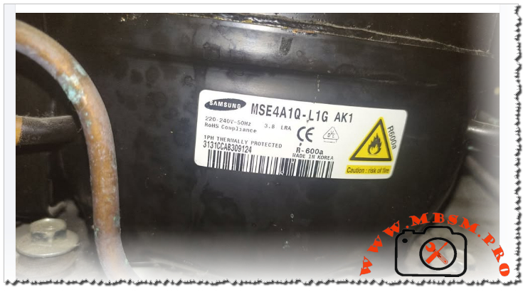
Samsung MSE4A1Q‑L1G AK1, hermetic reciprocating refrigerator compressor
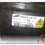
Samsung MSE4A1Q‑L1G AK1, 1/4 hp, R600a, RSCR, LBP, 220‑240V 50Hz Hermetic Compressor Technical Review
The Samsung MSE4A1Q‑L1G AK1 is a hermetic reciprocating refrigerator compressor designed for domestic LBP applications with R600a refrigerant and a nominal cooling capacity around 175–180 W at ASHRAE conditions, equivalent to roughly 1/4 hp.
Engineers value this model for its efficient RSCR motor, compatibility with eco‑friendly isobutane, and robust design for household refrigerators and freezers.
Main technical specifications
Samsung lists the MSE4A1Q‑L1G in its AC220‑240V 50 Hz R600a LBP family, sharing the same platform as MSE4A0Q and MSE4A2Q models used in many high‑efficiency fridges.
Core data of MSE4A1Q‑L1G AK1
The combination of ≈175–180 W cooling and ≈118 W electrical input places this compressor in the 1/4 hp class widely used in medium‑size top‑mount and bottom‑mount refrigerators.
Engineering view: performance and design
From an engineering perspective, the MSE4A1Q‑L1G AK1 is optimised for high efficiency at standard refrigerator evaporator temperatures while maintaining good starting torque with RSCR technology.
- The RSCR motor uses a start resistor and run capacitor to improve power factor and efficiency compared with simple RSIR designs, which helps manufacturers meet modern energy‑label targets.
- R600a’s low molecular weight and high latent heat allow lower displacement for the same cooling capacity, so the compressor can remain compact while delivering around 695 BTU/h of cooling at −23 °C evaporating conditions.
For technicians, the relatively low LRA of 3.8 A makes this model easier on start relays and PTC starters, especially in regions with weaker grid infrastructure at 220–240 V.
Comparison with other Samsung R600a LBP compressors
Samsung’s catalog groups the MSE4A1Q‑L1G within a family of R600a reciprocating compressors from about 94 W up to 223 W cooling capacity.
Position of MSE4A1Q‑L1G in the R600a range
| Model | Approx. cooling W (ASHRAE ST) | Input W | COP W/W | Approx. hp | Typical use | Source |
|---|---|---|---|---|---|---|
| MSE4A0Q‑L1G | 162–188 W | ≈107 W | ≈1.51 | ≈1/5–1/4 hp | Small to medium fridge | |
| MSE4A1Q‑L1G | 175–203 W | ≈118 W | ≈1.49 | ≈1/4 hp | Medium refrigerator, high‑efficiency | |
| MSE4A2Q‑L1H | 192–223 W | ≈127 W | ≈1.51 | ≈1/4+ hp | Larger fridge or combi | |
Compared with MSE4A0Q‑L1G, the MSE4A1Q‑L1G offers a modest step‑up in cooling capacity at similar efficiency, making it a good choice when cabinet size or ambient temperature requires extra margin.
Against MSE4A2Q‑L1H, it trades some maximum capacity for slightly lower input power, which can be attractive for manufacturers targeting stringent energy‑label thresholds while keeping the same mechanical footprint.
Professional installation and service advice
Working with R600a compressors like the MSE4A1Q‑L1G requires strict adherence to flammable‑refrigerant standards and best practices.
Key engineering and safety recommendations
- Use only tools and recovery systems rated for A3 refrigerants; never retrofit this compressor with R134a or other non‑approved gases because lubrication and motor cooling are optimised for R600a.
- Ensure the system charge is accurately weighed with a precision scale, as overcharging even small amounts can increase condensing pressure and reduce COP significantly on low‑displacement units.
- Maintain good airflow over the condenser and avoid installing units flush against walls; high condensing temperature quickly erodes the 1.49 W/W efficiency and can trigger thermal protector trips.
Diagnostic and replacement tips
- When replacing, match not only voltage and refrigerant but also cooling capacity and LBP application class; choosing a smaller 140 W class unit in place of the MSE4A1Q‑L1G risks long running times and poor pull‑down.
- Measure running current after start‑up; a healthy system will draw close to catalog input current at rated conditions, while notably higher current can indicate overcharge, blocked airflow, or partial winding short.
Focus keyphrase (Yoast SEO)
Samsung MSE4A1Q‑L1G AK1 1/4 hp R600a RSCR LBP refrigerator compressor 220‑240V 50Hz technical data and comparison
SEO title
Samsung MSE4A1Q‑L1G AK1, 1/4 hp, R600a, RSCR, LBP, 220‑240V 50Hz Compressor Technical Data | Mbsm.pro
Meta description
Discover the full technical profile of the Samsung MSE4A1Q‑L1G AK1 1/4 hp R600a LBP compressor: cooling capacity, RSCR motor efficiency, engineering advice, and comparisons with other Samsung R600a models.
Slug
samsung-mse4a1q-l1g-ak1-1-4hp-r600a-lbp-compressor-data
Tags
Samsung MSE4A1Q‑L1G, MSE4A1Q‑L1G AK1, Samsung R600a compressor, 1/4 hp refrigerator compressor, RSCR LBP compressor, 220‑240V 50Hz compressor, Mbsmgroup, Mbsm.pro, mbsmpro.com, mbsm
Excerpt (first 55 words)
The Samsung MSE4A1Q‑L1G AK1 is a hermetic reciprocating refrigerator compressor designed for domestic LBP applications with R600a refrigerant and a nominal cooling capacity around 175–180 W at ASHRAE conditions, equivalent to roughly 1/4 hp. Engineers value this model for its efficient RSCR motor and robust design.
Verified PDF and catalog links about Samsung R600a compressors
- Samsung global compressor page for AC220‑240V 50Hz R600a LBP family (includes MSE4A1Q‑L1G, PDF download link in page).
- Direct Samsung “SAMSUNG COMPRESSOR” R600a catalog PDF listing MSE4A1Q‑L1G specifications.
- Samsung AC200‑220V 50Hz R600a LBP compressor family catalog page with PDF.
- Samsung corporate brochure “Samsung Compressor” PDF covering technical data and performance tables.
- Spanish “Catalogo Compresores Samsung” PDF on Scribd with R600a LBP tables.
- Tili Global technical sheet collection for Samsung household reciprocating compressors (model tables in downloadable PDF).
- Samsung global business main compressor product brochure PDF linked from compressor overview section.
- Additional Samsung R600a LBP catalog PDF linked in “Download PDF” button for AC220‑240V 50Hz series on product page.
- Supplementary Samsung compressor specification PDF referenced within Scribd Samsung Compressor document.
- General Samsung reciprocating compressor catalog PDF referenced across global business compressor section, covering multiple R600a LBP models.