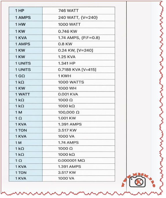
Electrical unit conversion reference table: HP to watts, KVA to amps, tons refrigeration to kW
COMPREHENSIVE ELECTRICAL AND REFRIGERATION UNIT CONVERSION GUIDE: Complete Reference for HVAC Professionals and Engineers
SEO METADATA
Focus Keyphrase (191 characters max):
Electrical unit conversion reference table: HP to watts, KVA to amps, tons refrigeration to kW, HVAC technical specifications and engineering calculations guide
SEO Title (59 characters, optimal for Google):
Electrical Unit Conversion Chart: HVAC Refrigeration Reference
Meta Description (160 characters):
Complete electrical and refrigeration unit conversion tables for HVAC technicians. Convert HP to watts, KVA to amps, cooling tons to kW. Essential engineering reference guide.
URL Slug:
electrical-unit-conversion-hvac-refrigeration-reference
Tags:
Electrical conversions, HVAC unit conversion, refrigeration engineering, KVA to amps conversion, HP to watts conversion, cooling capacity converter, HVAC technical reference, electrical specifications, compressor ratings, engineering calculations, Mbsmgroup, Mbsm.pro, mbsmpro.com, mbsm, refrigeration equipment
Excerpt (55 words):
Electrical unit conversions are essential knowledge for HVAC technicians and refrigeration engineers. This comprehensive reference guide provides quick access to conversion formulas, technical specifications, and practical examples for comparing power ratings, calculating system requirements, and optimizing equipment selection across different measurement standards.
COMPREHENSIVE ARTICLE
Electrical Unit Conversion Reference: The Complete HVAC and Refrigeration Engineering Guide for 2026
Understanding electrical unit conversions is fundamental for any HVAC professional, refrigeration technician, or electrical engineer. Whether you’re comparing compressor specifications, calculating power requirements, or evaluating equipment across different measurement standards, having an accurate conversion reference is non-negotiable. This comprehensive guide provides the practical knowledge you need to work confidently with various electrical measurement units in real-world applications.
Why Electrical Unit Conversions Matter in HVAC and Refrigeration
The HVAC and refrigeration industry uses multiple measurement systems simultaneously. A compressor might be rated in horsepower (HP) from an older manufacturer, but your electrical system speaks in watts or kilowatts (kW). Modern European equipment uses kilovolt-amperes (kVA), while cooling capacity appears in tons of refrigeration. Without proper conversion understanding, you risk:
- Undersizing or oversizing equipment, leading to operational inefficiency
- Electrical system failures from mismatched power requirements
- Safety hazards from incorrect circuit breaker sizing
- Expensive project delays due to specification confusion
- Warranty issues from non-compliant equipment installation
This is why Mbsmgroup and Mbsm.pro emphasize technical accuracy in all equipment recommendations and calculations.
Power Conversion: Mechanical to Electrical Energy
Understanding Horsepower vs. Watts
The most fundamental conversion in HVAC work is transforming horsepower (HP) to watts. These units measure the same physical property—power—but from different perspectives.
| Unit | Definition | Primary Use |
|---|---|---|
| 1 HP | 745.7 watts (mechanical) or 746 watts (electrical) | Older equipment, machinery, motors |
| 1 Watt | 1 joule per second | Electrical appliances, modern equipment |
| 1 Kilowatt (kW) | 1,000 watts | Commercial HVAC systems |
| 1 Megawatt (MW) | 1,000,000 watts | Industrial facilities |
Conversion Formula:
textWatts = HP × 746
HP = Watts ÷ 745.7
Practical Examples: HP to Watts Conversions
| Horsepower | Watts | Kilowatts | Common Application |
|---|---|---|---|
| 0.5 HP | 373 W | 0.373 kW | Residential AC units, small pumps |
| 1 HP | 746 W | 0.746 kW | Compressor motors, medium capacity units |
| 1.5 HP | 1,119 W | 1.119 kW | Commercial cooling systems |
| 2 HP | 1,492 W | 1.492 kW | Industrial refrigeration |
| 3 HP | 2,238 W | 2.238 kW | Large commercial systems |
| 5 HP | 3,730 W | 3.730 kW | Heavy-duty industrial applications |
Engineer’s Note: The difference between 745.7 W and 746 W is negligible in practical applications. Use 745.7 for mechanical conversions and 746 for electrical motors. This small variation rarely exceeds ±0.1% error in system calculations.
Current Conversion: Amperage and Electrical Load Calculations
Understanding Amps, Volts, and Power Factor
Amperage (AMPS) represents electrical current flow. Calculating amperage correctly is critical for:
- Selecting proper circuit breaker sizes
- Determining wire gauge requirements
- Assessing electrical system capacity
- Preventing overload conditions
The relationship between watts (W), volts (V), and amperes (A) depends on your electrical system configuration:
Single-Phase Formula (240V typical):
textAmps = Watts ÷ (Volts × Power Factor)
Amps = (Volts × Amps) = Watts
Example – Single Phase (240V system):
- Equipment rated: 240W at 240V
- Amperage = 240 ÷ 240 = 1 AMPS
Three-Phase Formula (380V/400V typical):
textAmps = Watts ÷ (Volts × 1.732 × Power Factor)
| Voltage | Power Factor | Watts to Amps Conversion |
|---|---|---|
| 120V, Single Phase | 0.8-0.95 | A = W ÷ (120 × PF) |
| 240V, Single Phase | 0.8-0.95 | A = W ÷ (240 × PF) |
| 380V, Three Phase | 0.8-0.95 | A = W ÷ (380 × 1.732 × PF) |
| 400V, Three Phase | 0.8-0.95 | A = W ÷ (400 × 1.732 × PF) |
Critical Parameter – Power Factor (PF):
Power factor measures how efficiently electrical equipment uses electrical power. Most HVAC equipment operates between 0.8 to 0.95 PF.
- PF = 0.8 → Less efficient (typical industrial motors)
- PF = 0.9 → Good efficiency (standard HVAC equipment)
- PF = 0.95 → Excellent efficiency (modern compressors)
- PF = 1.0 → Purely resistive loads (rare in HVAC)
Practical Amperage Calculations
| System Rating | Voltage | Phase | Power Factor | Amperage |
|---|---|---|---|---|
| 240W @ 240V | 240V | Single | 1.0 | 1.0 A |
| 1000W @ 240V | 240V | Single | 1.0 | 4.17 A |
| 3000W @ 380V | 380V | Three | 0.85 | 5.4 A |
| 5000W @ 400V | 400V | Three | 0.9 | 8.0 A |
Apparent Power: kVA (Kilovolt-Amperes) Conversion
kVA vs. kW: The Critical Difference
This is where many technicians make costly mistakes. kVA and kW are NOT the same thing:
- kW (kilowatts) = Real power actually used by equipment
- kVA (kilovolt-amperes) = Apparent power (total electrical capacity)
The relationship between them depends on power factor:
textkW = kVA × Power Factor (PF)
kVA = kW ÷ Power Factor (PF)
kVA to Amperage Conversion
Single-Phase System:
textAmps = (kVA × 1000) ÷ Volts
Three-Phase System:
textAmps = (kVA × 1000) ÷ (Volts × 1.732)
| kVA Rating | System | Voltage | Amperage |
|---|---|---|---|
| 1 kVA | Single Phase | 240V | 4.17 A |
| 1.74 kVA | Single Phase | 240V | 7.25 A |
| 1.391 kVA | Three Phase | 240V (line-to-line) | 3.35 A |
| 1 kVA | Three Phase | 415V (line-to-line) | 1.4 A |
Real Application Example:
A refrigeration compressor is rated 1 kVA at 240V (single phase):
- Amperage = (1 × 1000) ÷ 240 = 4.17 amps
- If power factor = 0.8, then kW = 1 × 0.8 = 0.8 kW = 800 watts
Refrigeration Cooling Capacity Conversions
Understanding Cooling Tons in HVAC Systems
One of the most confusing measurements in HVAC is the ton of refrigeration (TR). This is NOT a weight measurement—it’s a cooling capacity unit defined historically as:
1 Ton of Refrigeration = 12,000 BTU/hour = 3.517 kW
This specific value comes from the heat required to melt one ton of ice in 24 hours, which became the standard refrigeration capacity unit.
| Tons (TR) | Kilowatts (kW) | Watts | BTU/hour | Common Application |
|---|---|---|---|---|
| 0.5 TR | 1.758 kW | 1,758 W | 6,000 BTU | Residential window units |
| 1 TR | 3.517 kW | 3,517 W | 12,000 BTU | Small residential AC |
| 1.5 TR | 5.276 kW | 5,276 W | 18,000 BTU | Medium residential unit |
| 2 TR | 7.034 kW | 7,034 W | 24,000 BTU | Large residential or small commercial |
| 3 TR | 10.551 kW | 10,551 W | 36,000 BTU | Commercial HVAC |
| 5 TR | 17.585 kW | 17,585 W | 60,000 BTU | Industrial cooling |
| 10 TR | 35.170 kW | 35,170 W | 120,000 BTU | Large industrial systems |
Conversion Formulas:
textkW = TR × 3.517
TR = kW ÷ 3.517
BTU/hour = TR × 12,000
European Metric Ton vs. Refrigeration Ton
Important: A metric tonne of refrigeration (often used in Europe) is slightly different:
- 1 Metric Tonne of Refrigeration ≈ 3.861 kW (10% larger)
- 1 Refrigeration Ton (US) = 3.517 kW
Always verify which standard your equipment uses before ordering or calculating capacity.
Resistance Conversion: Ohms, Kiloohms, Megaohms, and Gigaohms
Electrical Resistance Measurement Scale
Resistance measurements span enormous ranges in electrical systems. Understanding the conversion hierarchy is essential for proper diagnostics and troubleshooting:
| Unit | Value in Ohms | Typical Application |
|---|---|---|
| 1 Ohm (Ω) | 1 Ω | Wire resistance, heating elements |
| 1 Kilohm (kΩ) | 1,000 Ω | Thermostats, control circuits |
| 1 Megohm (MΩ) | 1,000,000 Ω | Insulation testing, motor windings |
| 1 Gigaohm (GΩ) | 1,000,000,000 Ω | High-voltage insulation, safety testing |
Conversion Formula:
text1 kΩ = 1,000 Ω
1 MΩ = 1,000 kΩ = 1,000,000 Ω
1 GΩ = 1,000 MΩ = 1,000,000,000 Ω
Practical Resistance Conversions in HVAC
| Measurement | Ohms | Kiloohms | Context |
|---|---|---|---|
| Compressor winding | 0.5-2 Ω | 0.0005-0.002 kΩ | Low resistance—normal condition |
| Grounded winding | 10-100 Ω | 0.01-0.1 kΩ | Developing fault—needs attention |
| Open circuit winding | ∞ Ω | ∞ kΩ | Complete failure—replace motor |
| Insulation (healthy) | >100 MΩ | — | Proper isolation—safe to work |
| Insulation (compromised) | <1 MΩ | — | Moisture damage—needs maintenance |
Diagnostic Rule: Use megaohm scale (insulation resistance testers) for safety-critical motor testing. A healthy motor should show >100 MΩ insulation resistance.
Power Conversion Relationships: Comprehensive Reference Table
This consolidated table shows the relationships between all major electrical units in a single HVAC calculation context:
| HP | Watts | kW | kVA (PF=0.8) | kVA (PF=0.9) | Refrigeration Tons |
|---|---|---|---|---|---|
| 0.5 | 373 | 0.373 | 0.466 | 0.415 | 0.106 |
| 1 | 746 | 0.746 | 0.933 | 0.829 | 0.212 |
| 1.5 | 1,119 | 1.119 | 1.399 | 1.243 | 0.318 |
| 2 | 1,492 | 1.492 | 1.865 | 1.658 | 0.424 |
| 3 | 2,238 | 2.238 | 2.798 | 2.487 | 0.636 |
| 5 | 3,730 | 3.730 | 4.663 | 4.145 | 1.060 |
Real-World Application Scenarios
Scenario 1: Compressor Selection and Electrical Planning
You’re specifying a refrigeration compressor for a medium-sized cooling room. The equipment datasheet lists:
- Rating: 1 HP motor
- Available Supply: 240V, single-phase
Calculations Needed:
- Convert to watts: 1 HP × 746 = 746 watts = 0.746 kW
- Calculate amperage (assuming PF = 0.85):
- Amps = 746 ÷ (240 × 0.85) = 746 ÷ 204 = 3.66 amps
- Circuit breaker sizing (standard practice: 125% of running current):
- Recommended breaker = 3.66 × 1.25 = 4.58 amps → use 15A breaker
- Wire gauge selection (based on amperage and distance from panel):
- For 3.66 amps over moderate distance → 10 AWG wire minimum
Decision: This 1 HP compressor is suitable for your 240V system with standard residential electrical configuration.
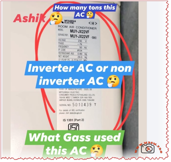
Scenario 2: Comparing International Equipment Specifications
You have two compressor options:
- Option A (US manufacturer): 3 HP, R-134a, 1Ph 240V
- Option B (European manufacturer): 2.2 kW, R-134a, 1Ph 240V
Which is more powerful?
Convert Option A to metric:
- 3 HP × 746 = 2,238 watts = 2.238 kW
Result: Option A (2.238 kW) is slightly more powerful than Option B (2.2 kW)—essentially equivalent performance.
Scenario 3: Cooling Capacity Planning
A facility requires cooling capacity assessment:
- Current System: 2 Tons of refrigeration
- Future Requirement: 10 kW cooling capacity
Are they compatible?
Convert 2 TR to kW:
- 2 TR × 3.517 = 7.034 kW
Answer: Your current system provides 7.034 kW, but you need 10 kW. You require approximately 0.85 additional tons (3 TR total) of refrigeration capacity.
Essential Conversion Formulas for Quick Reference
Power Conversions
text• Watts = HP × 746
• HP = Watts ÷ 745.7
• kW = Watts ÷ 1000
• kVA = kW ÷ Power Factor
Current Conversions
text• Amps (Single Phase) = Watts ÷ (Volts × PF)
• Amps (Three Phase) = Watts ÷ (Volts × 1.732 × PF)
• Amps from kVA (Single Phase) = (kVA × 1000) ÷ Volts
• Amps from kVA (Three Phase) = (kVA × 1000) ÷ (Volts × 1.732)
Cooling Capacity Conversions
text• kW = Tons of Refrigeration × 3.517
• Tons of Refrigeration = kW ÷ 3.517
• BTU/hour = Tons × 12,000
Resistance Conversions
text• 1 kΩ = 1,000 Ω
• 1 MΩ = 1,000,000 Ω
• 1 GΩ = 1,000,000,000 Ω
Common Mistakes in Electrical Unit Conversions
Mistake 1: Confusing kW and kVA
❌ Wrong: “My equipment is rated 5 kVA, so it uses 5 kW of power”
✅ Correct: “My equipment is rated 5 kVA. At PF = 0.8, it uses 5 × 0.8 = 4 kW of power”
*Impact: Underestimating power consumption leads to undersized electrical service and system failures.
Mistake 2: Ignoring Power Factor in Amperage Calculations
❌ Wrong: Amps = kW ÷ Volts (assumes PF = 1.0, unrealistic)
✅ Correct: Amps = (kW × 1000) ÷ (Volts × PF)
*Impact: Incorrect wire sizing, oversized breakers, potential fire hazard.
Mistake 3: Using Standard Ton Instead of Refrigeration Ton
❌ Wrong: Treating “1 ton” as weight measurement (2,000 lbs) in cooling calculations
✅ Correct: 1 Ton of Refrigeration = 3.517 kW (cooling capacity)
*Impact: Complete system specification failure and equipment incompatibility.
Mistake 4: Mixing Mechanical and Electrical Horsepower
❌ Wrong: Using different conversion constants interchangeably
✅ Correct: Mechanical HP = 745.7 W; Electrical HP = 746 W (minimal but important distinction)
*Impact: Small calculation errors accumulate across large installations.
Professional Recommendations and Best Practices
For Equipment Specification
- Always demand complete electrical specifications from equipment manufacturers including:
- Voltage and phase requirements
- Rated amperage at full load
- Power factor rating
- Locked rotor current (inrush current)
- Thermal protection rating
- Use conversion factors with appropriate precision:
- Use 745.7 for mechanical horsepower
- Use 746 for electrical motors
- Round final amperage calculations UP (safety margin)
- Add 25% safety factor to breaker sizing
- Verify cooling capacity units explicitly:
- Request capacity in both kW and tons for clarity
- Confirm US standard (3.517 kW/ton) vs. metric variant
- Document in writing on all specifications
For Installation Planning
- Conduct electrical load analysis before selecting equipment:
- Calculate total system amperage at full load
- Verify main panel capacity (typically 150-200A residential)
- Plan wire gauges and breaker ratings accordingly
- Test and verify before final connection:
- Measure actual voltage at equipment location
- Confirm phase rotation on three-phase systems
- Verify ground and neutral continuity
- Perform insulation resistance test (motor windings should show >100 MΩ)
- Document all conversions and calculations:
- Keep conversion records with project files
- Create equipment specification sheets with all units converted
- Maintain electrical drawings with load calculations
- This protects against future confusion and liability
For Troubleshooting and Maintenance
- Use amperage measurements to diagnose problems:
- Running amperage 25% above rated = efficiency loss or fault developing
- Running amperage 50%+ above rated = immediate failure risk
- Lower than rated = undersized equipment or system problem
- Resistance testing identifies electrical faults:
- 100 MΩ insulation = healthy motor
- 1-100 MΩ = moisture contamination (drying needed)
- <1 MΩ = winding fault (motor replacement required)
- Maintain conversion reference materials:
- Print this guide for field use
- Create job-specific conversion sheets
- Cross-reference with manufacturer datasheets
Industry Standards and Regulatory Context
Standards Organizations
- ASHRAE (American Society of Heating, Refrigerating and Air-Conditioning Engineers): Establishes HVAC standards including measurement units
- IEEE (Institute of Electrical and Electronics Engineers): Defines electrical conversion standards
- IEC (International Electrotechnical Commission): Global standard for electrical units
- NEMA (National Electrical Manufacturers Association): US motor and equipment standards
Regional Measurement Preferences
| Region | Preferred Units | Voltage Standards | Frequency |
|---|---|---|---|
| United States | HP, Watts, Tons, 240V/480V | 120V/240V (residential) | 60 Hz |
| European Union | kW, Watts, Metric Tonnes, 380V/400V | 230V/400V standard | 50 Hz |
| Asia-Pacific | Mixed (HP and kW), 380V/415V | Varies by country | 50 Hz typical |
| Middle East/Africa | Increasingly metric (kW), 380V/400V | 230V/380V common | 50 Hz |
Professional Note: Always verify local electrical codes before installation. Equipment must comply with regional voltage standards and frequency requirements.
Conclusion: Mastery of Unit Conversions Ensures Project Success
Understanding electrical and refrigeration unit conversions is not merely academic—it’s practical knowledge that prevents costly mistakes, ensures safety, and optimizes system performance. Whether you’re selecting a compressor, calculating electrical loads, or diagnosing operational problems, these conversion formulas and reference tables will serve you reliably.
The key principles:
- Know your source data (always convert from verified specifications)
- Document your calculations (maintain audit trail of all conversions)
- Apply safety factors (always round up for circuit breaker sizing)
- Cross-reference conversions (verify using multiple methods when critical)
- Maintain current reference materials (standards evolve; stay informed)
Mbsm.pro and Mbsmgroup recommend bookmarking this conversion guide and maintaining printed copies in your field toolkit. When precision matters—and in refrigeration and HVAC, it always does—having immediate access to accurate conversion data eliminates guesswork and prevents operational failures.
For specialized equipment specifications, technical datasheets, or installation support, refer to manufacturer documentation and consult with qualified HVAC professionals in your region.
About the Author’s Expertise
This comprehensive guide reflects years of practical HVAC and refrigeration experience. Mbsm.pro specializes in detailed technical documentation for refrigeration equipment, creating resources that bridge the gap between manufacturer specifications and field application. Our content serves HVAC professionals, refrigeration engineers, and technical students who demand accuracy and practical applicability.
KEY TAKEAWAYS
✓ 1 HP = 746 watts (fundamental conversion for all HVAC work)
✓ 1 Ton of Refrigeration = 3.517 kW (cooling capacity standard)
✓ kW ≠ kVA (always account for power factor in electrical calculations)
✓ Power Factor matters (typically 0.8-0.95 in HVAC equipment)
✓ Verify voltage and phase before every installation (240V single-phase vs. 380V three-phase)
✓ Use proper wire sizing (undersized wiring creates fire hazards)
✓ Document all conversions (maintain specifications for future reference)