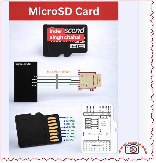
MicroSD cards connect to microcontrollers over SPI or SDIO
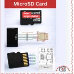
MicroSD cards connect to microcontrollers over SPI or SDIO; use a 3.3 V level interface, wire CS/MOSI/MISO/SCK correctly, add a 5 V → 3.3 V level shifter when needed, and follow pinout and decoupling best practices for reliable data logging and boot storage.
MicroSD Interface and Pinout
MicroSD cards expose an 8‑pin interface that maps to SPI signals when used in SPI mode: CS (chip select), MOSI (CMD/DI), MISO (DAT0/DO), and SCK (CLK). Use a 3.3 V supply and a proper level converter when your MCU is 5 V tolerant.
Key wiring notes: CS to a dedicated GPIO, MOSI to MCU MOSI, MISO to MCU MISO, SCK to MCU SCK, and VDD/VSS to 3.3 V and ground respectively.
Protocol Options and When to Use Each
| Criterion | SPI Mode | SDIO/Native Mode |
|---|---|---|
| Complexity | Low | Higher |
| Speed | Moderate | Higher throughput |
| MCU Pins | 4 | 4–9 depending on bus width |
| Use case | Data logging, simple read/write | High‑speed multimedia, OS boot |
Sources: .
Practical Wiring Table
| MicroSD Pin | SPI Signal | MCU Connection |
|---|---|---|
| DAT3 | CS | GPIO (CS) |
| CMD | MOSI / DI | MCU MOSI |
| DAT0 | MISO / DO | MCU MISO |
| CLK | SCK | MCU SCK |
| VDD | VCC | 3.3 V |
| VSS | GND | GND |
Follow the standard pin mapping and confirm with your card socket documentation before soldering.
Design Values and Component Choices
- Level shifting: Use a proper 5 V → 3.3 V bidirectional level shifter or MOSFET‑based translator for data lines when the MCU is 5 V.
- Decoupling: 0.1 µF ceramic + 10 µF electrolytic on VDD close to the card socket to stabilize supply during bursts.
- Pull‑ups: Some SD cards require weak pull‑ups on CMD and DAT lines in certain modes; check the card behavior during initialization.
- Clock speed: Start at 400 kHz for initialization, then increase to the MCU and card supported maximum for throughput.
Common Mistakes and How to Avoid Them
- No level shifting → card damage or unreliable communication.
- Long traces and poor layout → signal reflections and data errors; keep traces short and use ground plane.
- Insufficient decoupling → resets or write failures during high current spikes.
- Wrong pin mapping → permanent socket damage; always verify pin labels and orientation.
Value Comparisons and Tradeoffs
- SPI is simpler and widely supported by microcontroller libraries; SDIO gives higher throughput but requires more complex drivers and hardware support.
- For data logging and firmware storage, SPI mode is usually sufficient and easier to implement quickly.
Benefits and Notices
- Benefits: Compact removable storage, high capacity, low cost, and easy integration with MCU SPI peripherals.
- Notices: Always use 3.3 V supply, protect against ESD, and avoid hot‑plugging in sensitive systems without buffering.
Focus Keyphrase MicroSD card SPI interface wiring CS MOSI MISO SCK 3.3V level shifter pinout microcontroller data logging boot storage
SEO Title Mbsmpro.com, MicroSD Interface, SPI Wiring, CS MOSI MISO SCK, 3.3V Level Shifter, Pinout, Data Logging
Meta Description Complete MicroSD wiring and pinout guide for microcontrollers: SPI mapping, level shifting, decoupling values, common mistakes, and protocol tradeoffs for reliable data logging and boot storage.
Slug microsd-spi-wiring-pinout-3-3v-level-shifter-data-logging
Tags MicroSD, SPI, SDIO, Pinout, CS, MOSI, MISO, SCK, Level Shifter, Mbsmgroup, Mbsm.pro, mbsmpro.com, mbsm, Data Logging
Excerpt MicroSD cards connect to microcontrollers via SPI or SDIO. This guide covers pinout mapping, 3.3 V level shifting, decoupling values, common wiring mistakes, and protocol tradeoffs for reliable data logging and boot storage.