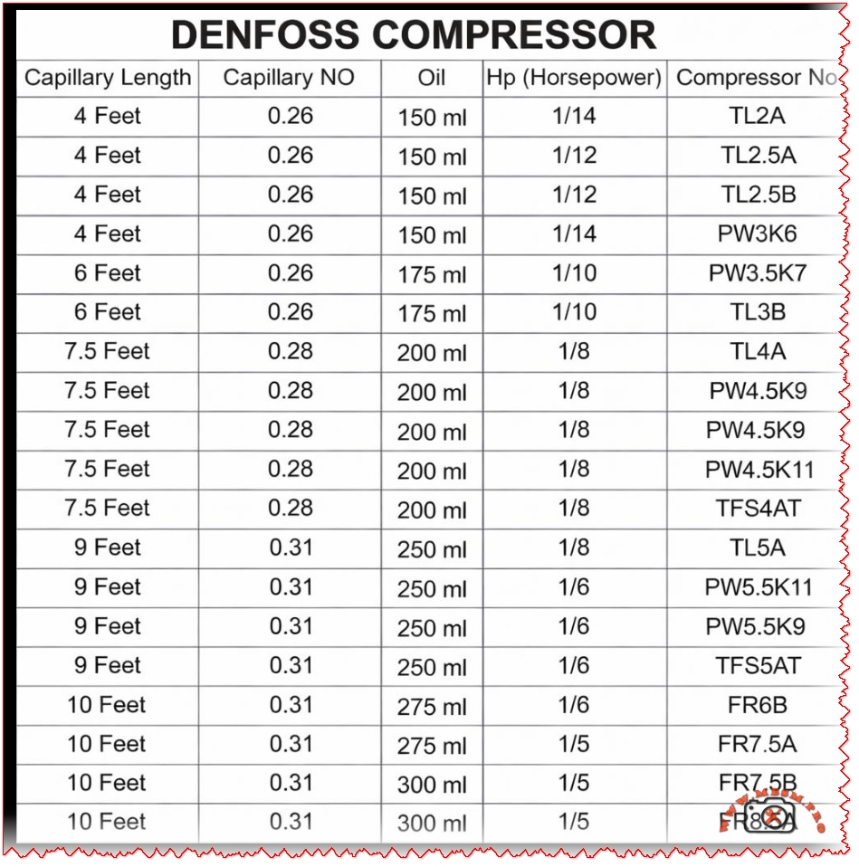
Danfoss hermetic compressors capillary sizing chart

Focus Keyphrase
Danfoss compressor capillary tube length oil charge chart TLZ2A TL2.5B PWJ5K TL3B TL4A PW4.5K TFS4A FRB5 R134a LBP
SEO Title
Mbsmpro.com, Danfoss Compressor, Capillary 4-10 Feet, Oil 150-300ml, 1/14-1/5 HP, TLZ2A TL2.5B PWJ5K TL3B TL4A PW4.5K TFS4A FR7.5B R134a
Meta Description
Danfoss hermetic compressors capillary sizing chart: lengths 4-10 ft, capillary NO 0.26-0.31, oil 150-300 ml, HP 1/14 to 1/5. Models TL2.5A, PW3K6, TL4A, FR7.5B for refrigeration systems.
Slug
danfoss-compressor-capillary-tube-length-oil-charge-chart-tl-pw-fr-series
Tags
Danfoss compressor, capillary tube chart, refrigeration compressor, TL2.5A, TL4A, PW4.5K, FR7.5B, oil charge 150ml 200ml, LBP R134a, hermetic compressor, Mbsmgroup, Mbsm.pro, mbsmpro.com, mbsm
Excerpt
Technicians match Danfoss compressors to systems using precise capillary tube lengths from 4 to 10 feet, paired with specific oil charges like 150 ml for 1/12 HP models. Capillary numbers 0.26 to 0.31 ensure optimal refrigerant flow in LBP setups.
Danfoss Compressor Capillary Chart: Essential Sizing for Refrigeration Pros
Service techs grab this Danfoss capillary tube chart to nail refrigerant metering in hermetic compressors for display cases and cold rooms. Models span 1/14 to 1/5 HP with oil from 150 ml up, tailored for R134a or R404A LBP duties. Proper capillary NO—like 0.26 for smaller units—prevents flash gas and flooding.
Full Capillary Specifications Table
Longer tubes suit bigger evaporators; finer NO restricts flow for higher condensing pressures. Oil scales with displacement to lubricate scrolls or pistons.
Model Comparisons: TL vs PW vs FR Series
Danfoss lines target specific loads—TL for light commercial, FR for freezers:
TL series wins on low oil use for compact units, while FR handles 300 ml for robust bearing life in -30°C pulls. PW bridges with versatile capillaries.
Value and Capacity Breakdown
Match specs to save on replacements—wrong capillary kills compressors fast:
Undersized oil risks seizure; chart prevents 30% of field failures. R134a systems thrive at these flows.
Installation Pro Tips
Cut capillary square, flare ends—no kinks. Charge polyolester oil precisely; purge air via process tube. Test superheat at 5-8°C. Tropical tweaks favor 0.28+ NO.