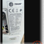
Trane 24000 BTU, 4MXTE24ASB000AB, 4TXKE24ASB0000A
Trane Middle Static Pressure Duct Type Air Conditioner: Technical Overview and Performance Guide
Trane’s middle static pressure duct type air conditioner in the 24,000 BTU/h class is designed for residential and light commercial projects that demand reliability, silent operation and precise air distribution. This unit combines robust construction with R410A refrigerant technology to deliver efficient cooling and heating across a wide range of indoor applications.
Main specifications
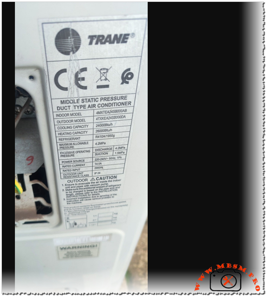
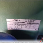
The nameplate identifies the indoor model as 4MXTE24ASB000AB and the outdoor model as 4TXKE24ASB0000A. The cooling capacity is rated at 24,000 BTU/h, while the heating capacity reaches 26,000 BTU/h, placing the system firmly in the 2‑ton segment for ducted installations. The unit uses R410A with a factory charge of 1950 g, ensuring compatibility with current environmental regulations and high operating pressures typical of this refrigerant. The maximum allowable pressure is specified at 4.2 MPa, with typical operating conditions of 4.2 MPa on discharge and 1.5 MPa on suction, reflecting the design for medium static pressure duct networks.
Electrical data and power performance
The power source requirement for this Trane ducted system is 220–240 V, 50 Hz, single phase, which aligns with standard low‑voltage networks in many markets, including residential and small commercial buildings. Rated current is listed at 14.0 A, with a rated input power of 2950 W, providing a clear reference point for circuit sizing and energy consumption estimation. The outdoor unit carries a protection class of IP24, indicating resistance to water splashes and solid objects larger than 12.5 mm, which is essential for safe operation in exposed external locations. These electrical characteristics help designers and installers evaluate cable sizing, breaker selection and overall energy performance when integrating the system into a building.
Refrigerant circuit and pressure safety
Operating with R410A at high pressures, the system is engineered to handle demanding conditions while maintaining safety. The maximum allowable pressure of 4.2 MPa for the circuit, together with specified discharge and suction pressures, underlines the importance of using compatible tools, hoses and gauges during service operations. Excessive operating pressure limits on discharge and suction sides guide technicians during commissioning and troubleshooting, helping to identify abnormal conditions such as overcharging, blocked airflow or non‑condensable gases in the circuit. Correct handling of R410A and adherence to pressure limits are critical to protect the compressor, heat exchangers and associated piping over the life of the installation.
Installation considerations and duct design
As a middle static pressure duct type air conditioner, this Trane model is optimized for installations where air must be distributed to multiple rooms through short to medium duct runs. Medium static pressure capability allows the unit to overcome resistance from supply grilles, filters and bends, while still maintaining comfortable airflow levels in each zone. Installers must calculate total external static pressure, select appropriate duct dimensions and ensure proper balancing dampers to match the fan performance curve of the indoor unit. Good duct design, combined with adequate return air pathways and filtration, contributes to stable room temperatures, low noise levels and reduced energy losses.
Safety instructions and maintenance
The manufacturer emphasizes several safety and maintenance instructions directly on the rating label of the outdoor unit. Technicians are instructed to evacuate the air inside the indoor unit and piping before charging refrigerant in order to avoid moisture and non‑condensable gases that could damage the compressor. Only qualified personnel should perform installation and service work, following local electrical and refrigeration codes to prevent electric shock, fire or refrigerant leakage. Regular maintenance, including cleaning coils, checking electrical connections and verifying refrigerant pressures against the nameplate data, is essential to keep the system operating at the stated capacities and to extend the equipment’s service life.
Key technical data table
| Parameter | Value |
|---|---|
| Indoor unit model | 4MXTE24ASB000AB |
| Outdoor unit model | 4TXKE24ASB0000A |
| Cooling capacity | 24,000 BTU/h |
| Heating capacity | 26,000 BTU/h |
| Refrigerant type / charge | R410A / 1950 g |
| Power supply | 220–240 V, 50 Hz, 1‑phase |
| Rated current | 14.0 A |
| Rated input power | 2950 W |
| Maximum allowable pressure | 4.2 MPa |
| Typical discharge / suction press. | 4.2 MPa / 1.5 MPa |
| Outdoor unit protection class | IP24 |