MADEL KCA‑SUB zoning control module: wiring, functions and professional applications

MADEL KCA‑SUB zoning control module: wiring, functions and professional applications

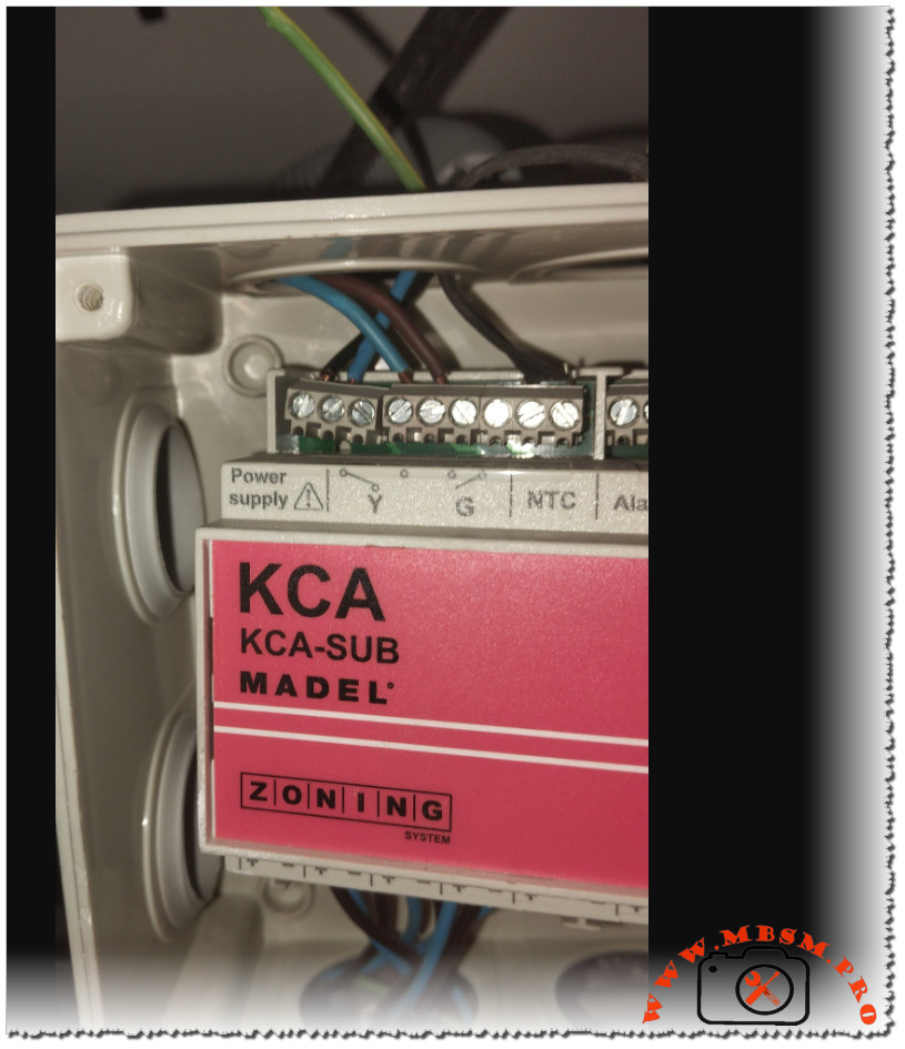
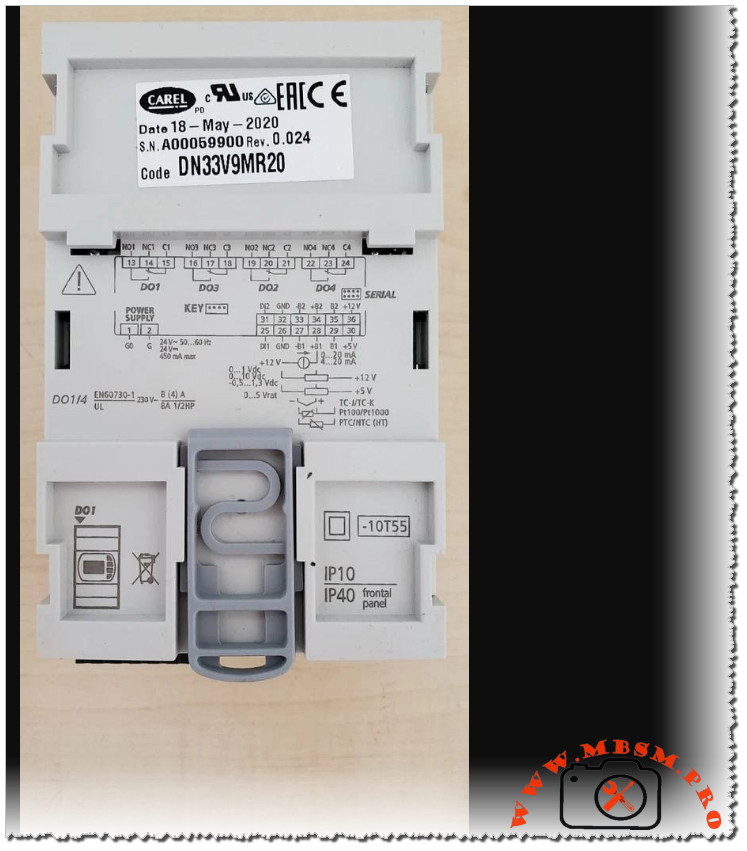
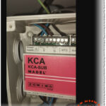
The MADEL KCA‑SUB is an electronic zoning controller designed to manage up to six independent air‑conditioning zones from a single ducted unit, improving comfort and energy efficiency in residential and light‑commercial projects. The photo shows the KCA‑SUB board installed in a junction box, with power, relay outputs and sensor terminals clearly labeled for field technicians.

Overview of the KCA‑SUB zoning system

The KCA‑SUB is part of MADEL’s Zoning System range, which uses motorized dampers and digital thermostats to regulate airflow to each room or zone. Each thermostat communicates with the control board via an RS485 bus, allowing centralized management of temperature and operation modes.

In “sub‑zone” configuration, the KCA‑SUB works on one to six branches of an existing ducted installation without modifying the logic of the main air‑conditioning unit. This makes it suitable for retrofits where only specific rooms need individualized temperature control.

Terminals and wiring shown in the image

On the upper edge of the module, the first block of terminals is reserved for the 230 V power supply and for control relays marked Y and G. According to the installer manual, Y and G are dry contacts intended to interface with the indoor unit’s cooling/heating and fan or start/stop inputs, following the wiring diagram provided by MADEL.

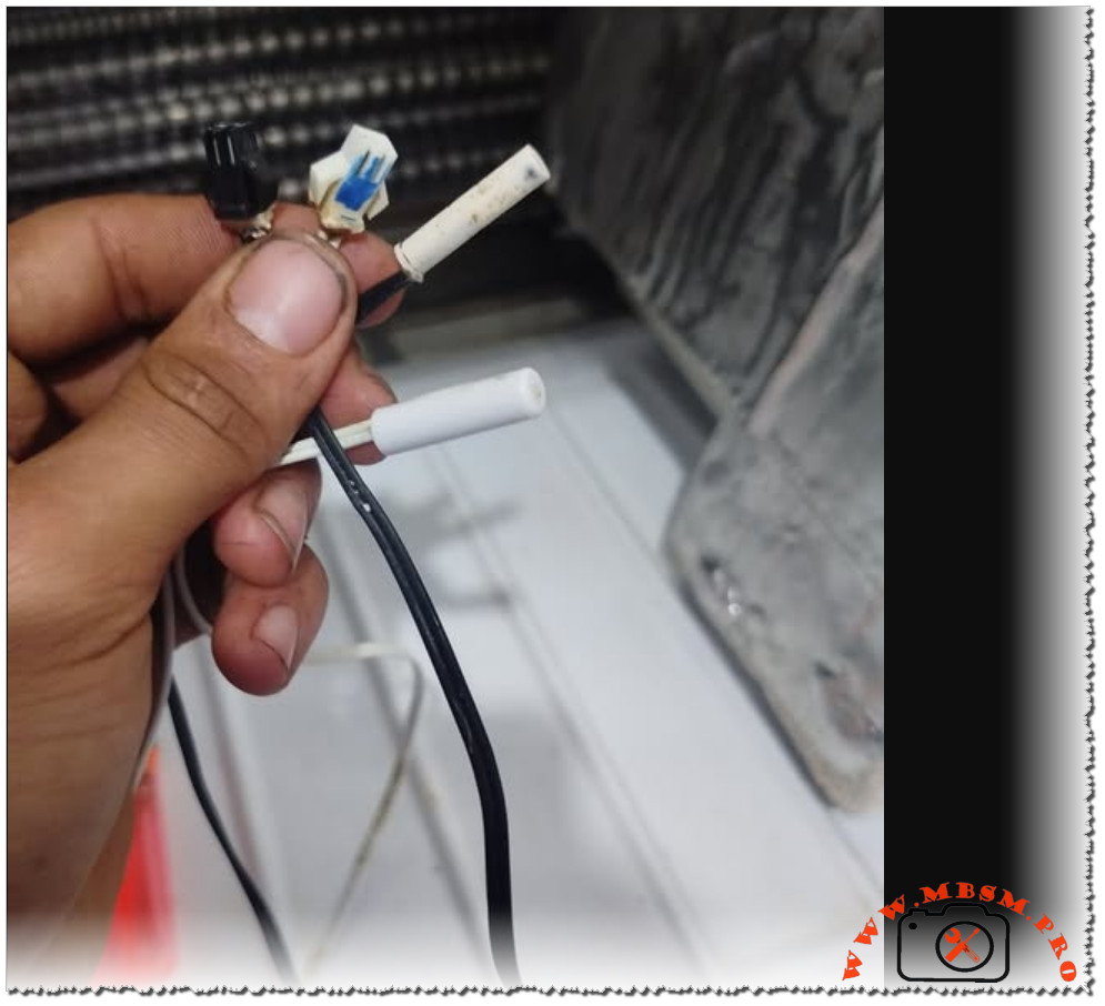
Next to the relay contacts, the board includes an NTC input for the return‑air sensor (typically a 10 kΩ thermistor) and an Alarm output that operates as a normally open potential‑free contact. In case of system fault, this alarm contact closes and can be connected to a BMS, a visual indicator or a safety circuit that shuts down the air‑handling unit.

Zoning channels and communication bus

The controller offers outputs for up to six motorized zone dampers, usually wired with red (positive) and black (negative) conductors for each actuator. The manual specifies a typical cable section between 0.75 and 1.0 mm² and recommends connecting any “master” zone to output 1 to ensure proper reference for system logic.

For communication, the KCA‑SUB uses an AB bus where terminal A is commonly wired in white and terminal B in blue, as also visible in many field installations. This two‑wire RS485 line links the control panel with all digital thermostats and must be daisy‑chained with correct polarity to guarantee stable communication.

Configuration and commissioning

Commissioning begins by supplying 230 VAC to the Power supply terminals and selecting the required number of zones with the rotary selector on the circuit board. Once the number of zones is set, technicians program each digital thermostat with its unique identification address and zone number using the SET‑UP menu described in the manual.

The controller can operate in classic “zoning” mode or in “sub‑zone” mode, where the KCA‑SUB manages only part of the installation while the original thermostat or controller keeps global authority over the unit. Seasonal change‑over between cooling and heating is typically commanded from the master thermostat, which sends the corresponding signal to the control board.

Operating indications and maintenance

Status LEDs on the front edge of the KCA‑SUB provide quick diagnostics for each zone and for the unit relays. In MADEL’s convention, a green LED indicates an open zone, a red LED indicates a closed zone, and illuminated Y or G LEDs mean that the respective relay is activated.

In case of malfunction, installers are instructed to verify wiring of dampers, sensors and the AB bus, then contact MADEL Technical Assistance Service if the fault persists. Regular inspection of damper movement, sensor placement in the return‑air duct and cleanliness of the control box help maintain reliable zoning performance over time.

Key technical data

Feature Description
Product name MADEL KCA‑SUB sub‑zone control panel for Zoning System.
Application Zoning of 1–6 branches on ducted HVAC installations (sub‑zone operation).
Power supply 230 VAC supply on dedicated terminals.
Zone outputs Up to 6 motorized dampers, red (+) and black (–) wires, 0.75–1.0 mm² conductors.
Communication RS485 AB bus (A = white, B = blue) for digital thermostats.
Sensors NTC 10 kΩ return‑air temperature probe on NTC terminal.
Unit control Y and G relay contacts to interface with indoor unit controls, on/off and mode.
Alarm output Potential‑free normally open contact, closes in alarm condition.


Electrostatic Paint Sprayer: Precision Coating for Modern Workshops

Electrostatic Paint Sprayer: Precision Coating for Modern Workshops

In many metalworking, HVAC and automotive workshops, an electrostatic paint sprayer has quietly become the secret weapon for achieving premium finishes with less paint and less mess. This compact system, often mounted on a mobile trolley with an integrated paint tank and control cabinet, charges each droplet of paint so it is strongly attracted to grounded metal parts. The result is a smooth, uniform coat that wraps around complex shapes while cutting material waste and spray‑booth pollution.

How an electrostatic sprayer works

At the heart of the system is a high‑voltage power supply that charges the paint as it leaves the spray gun nozzle. Charged particles repel each other, creating a fine, even mist that spreads uniformly across the target surface. When the workpiece is correctly grounded, those same particles are pulled in like iron filings to a magnet, covering corners, tubes and hidden edges that are often missed with conventional guns.

A typical workshop installation includes:

  • A stainless‑steel paint tank with secure lid and fittings for circulation and flushing.
  • A control column housing electrical and pneumatic controls, often shielded under a clear cover for safety.
  • Flexible hoses supplying paint and air to the gun, plus return lines for cleaning and color change.
  • A wheeled base, allowing the whole unit to move between production lines, vehicles or HVAC modules on site.

Key advantages for professional finishers

The biggest reason technicians move to electrostatic spraying is transfer efficiency. Because so much of the paint lands on the part instead of drifting away as overspray, manufacturers report efficiencies up to around 90%, compared with much lower figures for traditional air spray or HVLP equipment. That efficiency translates directly into cost savings on coatings, thinner layers of hazardous waste, and shorter booth cleaning cycles after each job.

Beyond savings, electrostatic systems deliver a noticeably better finish. The wrap‑around effect and consistent atomization create a smooth, uniform film even on complex geometries like compressor bodies, fan housings and tubular frames. This often means fewer passes, reduced risk of runs and sags, and less rework on high‑value components. For businesses like Mbsmgroup that work across HVAC, refrigeration and light industrial applications, that combination of quality and efficiency can be a significant competitive advantage.

Typical applications in metal, HVAC and automotive work

Electrostatic liquid systems are widely used wherever metal parts need durable, professional coatings. In HVAC and refrigeration workshops they are ideal for repainting cabinets, condensers, brackets and custom fabricated parts after repair or modification. In automotive environments, they are used on frames, panels, wheels and accessories where consistent film build is critical. They also appear in general manufacturing, coating everything from furniture frames to machinery guards.

Because the technology works with both solvent‑based and water‑based paints when the right gun and isolation strategy are used, one machine can often serve several product lines. Compact, mobile units – like the one pictured – make it possible for small and medium firms to benefit from the same technology used by large paint shops, without investing in a full robotic or conveyorized system.

Safety, maintenance and best practice

Electrostatic equipment concentrates energy and chemicals in one place, so good practice is essential. All workpieces and hangers must be well grounded for the charge to work and to avoid dangerous sparking; operators should regularly clean hooks, clamps and racks so insulation from dried paint does not build up. Personal protective equipment – mask or respirator, gloves and coveralls – remains mandatory because the process still uses fine aerosols and potentially volatile solvents.

Routine maintenance tasks include flushing paint hoses and the stainless‑steel tank between colors, checking filters, and inspecting the high‑voltage cable and gun body for damage. A simple maintenance log helps track nozzle changes, pump service and safety checks, improving uptime and extending the life of the system in demanding workshop conditions.


Technical overview table

Feature Typical specification / description
Application method High‑voltage electrostatic liquid spray gun with adjustable voltage and paint flow.
Transfer efficiency Often up to about 90% in optimized conditions, reducing overspray and material waste.
Compatible coatings Solvent‑based and water‑based paints when used with appropriate isolation and hardware.
Ideal use cases Metal cabinets, frames, HVAC units, machinery, automotive parts and complex geometries.
Mobility and layout Mobile trolley with stainless tank, control cabinet and hoses for flexible positioning in the shop.


Carel DN33V9MR20 Universal Controller: Reliable DIN-Rail Control For Modern HVAC Systems

Carel DN33V9MR20 Universal Controller: Reliable DIN-Rail Control For Modern HVAC Systems

The Carel DN33V9MR20 is a compact universal electronic controller designed for DIN‑rail mounting, widely used in refrigeration, air‑conditioning and process cooling where accurate temperature and universal input management are required. Its robust construction, broad power‑supply range and flexible I/O configuration make it a trusted choice for OEMs and technicians looking for stable control with a small footprint.

Key technical overview

The DN33V9MR20 belongs to Carel’s IR33/DN33 “Universale” family, supporting multiple sensor types and control strategies in a single platform. It is supplied for DIN‑rail mounting, with front‑panel protection rated IP40 and overall device protection IP10, matching the markings visible on the housing.

  • Power supply: 12–24 Vac or 12–30 Vdc, allowing integration in low‑voltage cabinets and retrofit projects.
  • Inputs: 2 analogue inputs (2AI) and 2 digital inputs (2DI), suitable for NTC/PTC probes, Pt1000, 0–5 V or 0–20 mA depending on configuration.
  • Outputs: 1 relay / digital output (1DO) with buzzer and infrared receiver (BUZ, IR) for local and remote interaction.

Main functions and applications

Carel designed the DN33 line to manage temperature but also humidity, pressure and other signals when paired with compatible sensors, giving OEMs a single platform for various units. The controller can operate in “direct” or “reverse” mode, meaning it can drive cooling or heating stages depending on how the measured value must react to set‑point deviations.

  • Typical applications include refrigerated cabinets, small chillers, air‑handling units and process cooling panels where space is limited but high functionality is required.
  • Two independent control loops are available in the IR33/DN33 architecture, enabling simultaneous management of, for example, temperature and defrost or auxiliary outputs when used with multistage variants.

Installation and wiring highlights

The body of the DN33V9MR20, as seen in the image, shows clearly printed terminal numbers and internal diagrams that simplify cabinet work for technicians. DIN‑rail mounting speeds up installation while the plug‑in terminals, shared with the IR33 series, help reduce downtime during replacement or servicing.

  • The front label identifies the product code DN33V9MR20, manufacturing date and revision, which technicians should record for maintenance history and firmware compatibility.
  • Wiring diagrams on the housing indicate the correct connection of power supply, analogue probes, digital inputs and relay output, minimising wiring errors in the field.

User interface and integration

Although the DN33V9MR20 is a DIN‑rail model without an integrated front keypad, it is compatible with Carel’s external user interfaces and programming key, allowing quick parameter upload and cloning across multiple controllers. Infrared reception and an acoustic buzzer provide simple local feedback for alarms and set‑point adjustments when used with the appropriate accessories.

  • The series supports RS‑485 networking on selected variants, enabling connection to supervisory systems for remote monitoring and data logging in supermarkets or industrial plants.
  • Standard Carel parameter maps give installers access to control modes, sensor calibration, alarm thresholds and defrost strategies, ensuring the DN33V9MR20 can be tuned precisely to each HVAC or refrigeration application.

Technical data table

Feature DN33V9MR20 specification
Mounting DIN‑rail, compact housing DN33 series
Power supply 12–24 Vac, 12–30 Vdc (multi‑voltage)
Analogue inputs 2 AI (NTC/PTC, Pt1000, 0–5 V, 0–20 mA, depending on configuration)
Digital inputs 2 DI for door switches, compressor status or alarms
Outputs 1 relay / digital output with buzzer and IR receiver
Protection Front panel IP40, complete controller IP10
Typical uses Refrigerated cabinets, small chillers, HVAC units, process temperature control


Tecumseh CAJ9480T: The French‑Made Heart of Legacy R22 Cold Rooms

Tecumseh CAJ9480T: The French‑Made Heart of Legacy R22 Cold Rooms

On the faded nameplate of this weathered compressor shell, one line stands out with absolute clarity: CAJ9480T – R22/R502 – Made in France. It is the unmistakable signature of a Tecumseh L’Unité Hermétique fully hermetic compressor, a workhorse still beating quietly inside thousands of small cold rooms and refrigerated cabinets around the world.


Identifying the CAJ9480T from the label

The image shows a classic welded‑shell compressor with a rectangular white label fixed on the body and a smaller green Tecumseh/L’Unité sticker below it.
Printed on the label, the model CAJ9480T appears alongside the refrigerant family R22/R502, the voltage range 208–220 V – 50 Hz, and the note THERMALLY PROTECTED, confirming an internally protected single‑phase motor.
The mention Country of origin: France links this unit to Tecumseh’s European manufacturing line, known under the historic L’Unité Hermétique brand, widely used in commercial refrigeration.


Technical profile of the CAJ9480T

Behind this modest steel shell lies a carefully engineered medium‑temperature compressor designed for reliability more than show.

  • It is a fully hermetic reciprocating compressor, meaning the electric motor and pistons are sealed in the same welded housing, minimizing leaks and simplifying service on the field.
  • In most data sheets the CAJ9480T is rated around 5/8 HP for R22 at 230 V, 50 Hz, suitable for small cold rooms, counters and display cases working in positive temperatures.
  • Typical electrical figures published for this model include a Rated Load Amps (RLA) close to 4 A and a Locked Rotor Amps (LRA) around 24 A, values that match the LRA 24 marking on many factory labels.

The following table summarises the key technical characteristics generally associated with a Tecumseh CAJ9480T in R22 applications.

Parameter Typical CAJ9480T value
Compressor type Fully hermetic reciprocating piston
Nominal horsepower Approx. 5/8 HP (medium temperature)
Refrigerant R22 (older labels may mention R22/R502; some variants accept R438A)
Voltage / frequency 220–240 V, single phase, 50 Hz (voltage code F/FZ)
Displacement About 15.2 cm³/rev
Rated Load Amps (RLA) ≈ 3.9–4.0 A at 50 Hz
Locked Rotor Amps (LRA) ≈ 24 A
Motor type CSR, high‑start torque with start and run capacitor
Oil charge Around 475–780 ml, mineral or alkylbenzene depending on version
Origin Tecumseh / L’Unité Hermétique, France

These values are essential for technicians who want to cross‑check compatibility when replacing a damaged unit or when sizing contactors, cables and protections.


Real‑world applications and typical uses

For many shop owners, the CAJ9480T is not a product code but “the compressor in the cold room that never stops”.

  • It is widely installed in small walk‑in cold rooms, butcher counters, beverage coolers and positive‑temperature cabinets where cooling capacity around 2 kW at medium evaporating temperatures is sufficient.
  • The evaporating temperature envelope usually runs from roughly –23 °C up to +12 °C, allowing the same base model to work in both cooler and slightly higher temperature applications when correctly selected.
  • Because R22 has been phased down in many markets, the CAJ9480T often appears in maintenance and retrofit projects: technicians may replace the original compressor with the same reference, or move to compatible alternative refrigerants when regulations and Tecumseh documentation allow it.

In all cases, checking the exact family (CAJ9480T‑FZ, CAJ9480T‑AJ2, etc.) is crucial, as each variant is optimized for specific refrigerants, voltages and accessories.


Installation notes from the field

Even the best compressor will not forgive poor installation. Technicians who work daily with CAJ‑series models usually insist on a few practical rules:

  • Clean piping and proper brazing: use nitrogen during brazing, replace the filter drier, and avoid introducing scale or moisture, which can quickly degrade the oil and shorten compressor life.
  • Accurate vacuum and charge: a deep vacuum combined with a charge adjusted to sight glass, superheat and manufacturer charts protects the compressor from liquid slugging and overheating.
  • Respect of operating envelope: the Tecumseh performance sheets show clear limits for high condensing temperatures and low evaporating pressures; staying inside this window prevents excessive motor current and thermal overload trips.
  • Correct starting equipment: since the CAJ9480T uses a CSR motor, the correct run capacitor, start capacitor and potential relay must be installed and wired following the original schematic to avoid hard starts and nuisance tripping.

For older R22 equipment, technicians also need to keep an eye on evolving regulations and encourage owners to plan long‑term upgrades towards more sustainable refrigerants and systems.


Replacing Unionaire Sensors with Kiriazi Deep Freezer Probes: What Technicians Must Check First

Replacing Unionaire Sensors with Kiriazi Deep Freezer Probes: What Technicians Must Check First

The picture shows a refrigeration technician holding several tubular temperature probes and a small white connector in front of a heavily frosted evaporator, a very typical scene when diagnosing a sensor fault in a no‑frost fridge or deep freezer. This raises the key question many technicians ask: can a Union Air (Unionaire) refrigerator or freezer sensor be safely replaced with a sensor taken from a Kiriazi deep freezer, without compromising performance or safety?


Understanding the Type of Sensors in Modern Fridges

  • Most Unionaire and Kiriazi appliances use NTC thermistor sensors whose resistance changes with temperature, commonly 5 kΩ or 10 kΩ at 25 °C for domestic refrigeration.
  • The probe is encapsulated in a plastic or metal tube, just like the white tubes visible in the image, and is fixed on the evaporator or in the air duct to measure cabinet or coil temperature accurately.​
  • The electronic control board reads the NTC value and converts it into on/off commands for the compressor and defrost heater, so any mismatch in sensor value directly alters the unit’s cooling and defrost behaviour.​

When Can a Kiriazi Sensor Replace a Unionaire Sensor?

  • A Kiriazi deep freezer probe can be used as a substitute for a Unionaire sensor only if the sensor type (NTC) and the nominal resistance (for example 5 kΩ or 10 kΩ at 25 °C) are the same, which is true for many domestic fridge and freezer models.
  • Before installing, measure the resistance of both the old Unionaire sensor and the Kiriazi sensor with a multimeter at room temperature and again in ice water; if values are very close (within roughly 5–10%), the replacement will usually work without noticeable set‑point error.​
  • You also need to confirm wire length and connector type; some Kiriazi probes come with a connector that matches Unionaire, while in other cases you must move the original plug onto the new leads or use well‑insulated crimp joints, as the hand‑held bundle in the photo suggests.​

Practical Replacement Steps for Field Technicians

  • Always disconnect mains power before touching sensors or the control board to avoid electric shock and prevent damage to the PCB.​
  • Gently remove the faulty sensor from its clip on the evaporator or from the air channel, then measure its resistance at ambient and at approximately 0 °C in a cup of ice water to compare with the new Kiriazi probe.​
  • Install the new probe exactly where the original was, making sure it has good thermal contact with the evaporator surface or sits correctly in the airflow path, then secure it using clips or cable ties as is common in no‑frost cabinets.​​

Risks If the Sensor Specifications Do Not Match

  • If the substitute sensor has a significantly different resistance curve, the fridge may run for too long, creating heavy ice build‑up like that visible in the background of the image, or may cut off early and never reach proper freezing temperature, leading to “not freezing enough” complaints.​​
  • A mismatched NTC curve can confuse the automatic defrost cycle, causing recurrent issues such as blocked drain channels, solid ice around the evaporator, and poor air circulation inside the freezer compartment.
  • On some digital Unionaire models, using the wrong sensor value can trigger repeated error codes or short cycling of the compressor, which shortens compressor life and annoys the customer with noisy, frequent starts.​​

Key Comparison Points Between Typical Unionaire and Kiriazi Probes

Item Unionaire digital fridge sensor Kiriazi domestic deep freezer sensor
Sensor type NTC thermistor NTC thermistor
Typical nominal value About 5 kΩ or 10 kΩ at 25 °C About 5 kΩ or 10 kΩ at 25 °C
Encapsulation style White/transparent plastic tube White plastic or metal tube
Common mounting location On evaporator or in air channel On evaporator or clipped to coil​
Connector style 2‑wire, small rectangular plug 2‑wire plug or bare leads​
Use as replacement Accepts equivalent NTC values Can act as substitute when values match

Pro Tips for Mbsmgroup and Mbsmpro Technicians

  • Keep a stock of universal NTC probes (5 kΩ and 10 kΩ) plus resistance charts; this makes it easier to service Unionaire, Kiriazi, and other brands with one organized sensor kit.
  • Before handing the appliance back to the customer, monitor freezer temperature for about 24 hours; ideally the internal thermometer should stabilise around −18 °C to −22 °C under normal conditions, and the defrost cycle should run without excessive ice accumulation.