Zener Diode Series 1N746 to 1N5369 Overview

The Ultimate Guide to Zener Diode Series: From 1N746 to 1N5369

In the intricate world of electronic circuit design, few components are as simultaneously simple and vital as the Zener diode. Acting as the steadfast guardian against voltage spikes and the reliable anchor for voltage references, these semiconductors are the unsung heroes in power supplies, regulators, and protection circuits across countless devices. Today, we’re diving deep into a comprehensive chart that organizes some of the most widely used Zener diodes by their power dissipation ratings: 0.5 Watt, 1 Watt, and 5 Watt.

Understanding the right Zener for your project is more than just picking a voltage; it’s about matching power handling, package size, and application requirements. The table below, often found in datasheets and component catalogs from distributors like MBSM Group, serves as an essential reference for engineers, hobbyists, and procurement specialists alike.

Zener Diode Voltage & Part Number Reference Chart

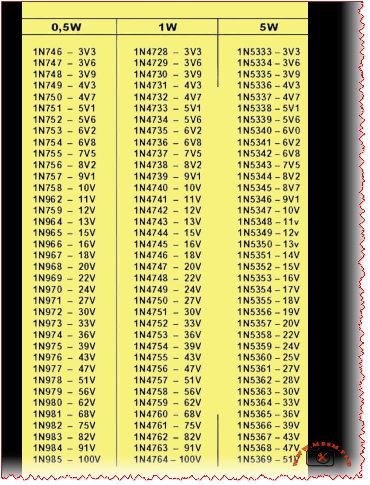
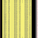
The following table cross-references three major Zener diode families, organized by their nominal Zener voltage. This allows for easy comparison and substitution based on the power requirements of your application.

0.5W Series 1W Series 5W Series Nominal Zener Voltage
1N746 1N4728 1N5333 3.3V
1N747 1N4729 1N5334 3.6V
1N748 1N4730 1N5335 3.9V
1N749 1N4731 1N5336 4.3V
1N750 1N4732 1N5337 4.7V
1N751 1N4733 1N5338 5.1V
1N752 1N4734 1N5339 5.6V
1N753 1N4735 1N5340 6.0V / 6.2V*
1N754 1N4736 1N5341 6.8V
1N755 1N4737 1N5342 7.5V
… (and so on, up to 100V)

*Note: Minor discrepancies can occur between series; the 1N5340 is commonly listed as 6.0V, while the 0.5W/1W equivalents are 6.2V. Always consult the specific datasheet.*

Decoding the Ratings: 0.5W vs. 1W vs. 5W

So, what’s the real-world difference between these series? It boils down to power dissipation and physical size.

  • 0.5W Series (e.g., 1N746-1N985): These are typically housed in small glass DO-35 packages. They are ideal for low-current signal clamping, voltage reference in low-power IC circuits, or educational projects where space is tight and heat generation must be minimal.
  • 1W Series (e.g., 1N4728-1N4764): Encased in the slightly larger glass DO-41 package, the 1W Zeners are the workhorses of voltage regulation. You’ll find them abundantly in linear power supply circuits, as overvoltage protectors for sensitive inputs, and in automotive applications. They offer a robust balance of capability and size.
  • 5W Series (e.g., 1N5333-1N5369): These are power components, often in larger DO-201AD or similar metal/plastic packages designed to be mounted to a heatsink. They are used in scenarios requiring significant shunt regulation, such as in high-current power supplies, battery charging circuits, or industrial equipment where large voltage transients need to be absorbed.

Choosing the correct series is critical. Using a 0.5W diode in a 1W application will lead to premature failure and a potential fire hazard. Conversely, using a 5W diode where a 0.5W would suffice is an inefficient use of board space and budget.

Practical Applications in Circuit Design

How are these components used? Let’s look at two classic examples:

  1. Voltage Regulation: A 1N4733A (5.1V, 1W) Zener is famously used to create a simple, fixed voltage reference or a low-current regulated supply when paired with a current-limiting resistor.
  2. Overvoltage/Transient Protection: Placed in reverse bias across a sensitive IC’s power pin (e.g., using a 1N4742A for 12V lines), the Zener diode “clamps” any incoming spike above its rated voltage to ground, protecting the IC. The higher-power 5W series excel in protecting entire power rails.

Sourcing and Reliable Information

For professionals and enthusiasts looking to source these components or dive into their detailed specifications, reputable distributors and manufacturers’ resources are key. Here are some valuable links:

  • Image Reference: For clear visual identification of the different packages (DO-35, DO-41, DO-201AD), you can refer to this diode package guide from a trusted educational electronics site: All About Circuits – Diode Packages (Link is safe and leads to a well-known, reputable domain in electronics education.)
  • Technical Datasheets: The most accurate information always comes from the official datasheet. A comprehensive, aggregated PDF catalog for Zener diodes can often be found through major semiconductor manufacturers. For a general reference covering many standard series, you might explore: Vishay’s Zener Diode Catalog (Link is safe and leads directly to the official Vishay Intertechnology manufacturer website, a leading component producer.) Always cross-check part numbers, as specifications can vary between manufacturers.

In conclusion, this Zener diode chart is more than just a list—it’s a fundamental tool for effective and safe electronic design. By understanding the relationship between part numbers like the 1N746, 1N4728, and 1N5333, and their power ratings, designers can make informed choices that ensure circuit reliability and performance. Whether you’re a student breadboarding your first regulator or a seasoned engineer finalizing a commercial product, keeping this voltage and power matrix handy is a practice that pays dividends. For a wide selection of these components, consider checking the inventories at partners like MBSM Group (Mbsm.pro).


SCE SCOOP

Inside the SECOP SCE Hermetic Compressor: A Complete Exploded View and Parts Identification Guide

For technicians, engineers, and procurement specialists in the commercial refrigeration industry, understanding the internal anatomy of a compressor is not just academic—it’s essential for efficient maintenance, accurate troubleshooting, and reliable sourcing of spare parts. The SECOP SCE series hermetic compressor is a cornerstone in many refrigeration systems, known for its durability and performance. This article provides a comprehensive, journalistic breakdown of its internal components using a detailed exploded view, serving as your definitive visual and technical guide.

Decoding the Exploded View: A Systematic Walkthrough

An exploded view diagram is more than just a parts list; it’s a roadmap to the machine’s soul. It shows how individual components interact within the sealed “hermetic” shell, where the motor and compressor are welded shut to protect against refrigerant and moisture. Let’s navigate the key assemblies revealed in the SCE compressor diagram.

1. The Core Compression Assembly

This is the heart of the compressor, where mechanical motion translates into refrigerant compression.

  • Piston (11) & Cylinder (Part of Crankcase 15): The piston moves within the cylinder bore, creating the vacuum and pressure cycles.
  • Crankshaft (8): Driven by the motor, its rotational motion is converted into the piston’s reciprocating motion via the connecting rod (9) and wrist pin (10).
  • Valve System: This critical assembly manages refrigerant flow. The suction valve (17) opens to draw in low-pressure gas. The discharge valve (18), held by its stopper (19), opens to release high-pressure gas into the discharge muffler.

2. The Electrical & Drive Assembly

Nestled beneath the compressor, this assembly powers the entire system.

  • Stator (27): The stationary part of the electric motor, containing copper windings, housed inside the stator case (28).
  • Rotor (25): Pressed onto the crankshaft (8), it rotates within the stator’s magnetic field.
  • Hermetic Terminal (31): The vital electrical pass-through that allows power cables to enter the sealed compressor housing without leaking refrigerant.

3. Structural & Ancillary Components

These parts provide support, balance, and necessary functionalities.

  • Compressor Housing (30): The iconic welded steel shell that contains all components.
  • Suspension Springs (29): Isolate vibrations, preventing noise and wear from transmitting to the refrigeration cabinet.
  • Oil Pump (26): Often a centrifugal type on the crankshaft, it ensures critical lubrication reaches the upper bearing (7) and other moving parts.
  • Counterweight (6): Balances the rotating assembly to minimize vibration, secured by a screw (4) and sometimes accompanied by a slinger (5).

Complete SECOP SCE Compressor Parts Reference Table

For quick reference and cross-referencing with part numbers, here is a complete table of the components identified in the exploded view:

Item No. Part Name Primary Function
01 Compressor Cover Protects internal parts, forms suction chamber
02 Suction Connector Inlet for low-pressure refrigerant gas
03 Discharge Connector Outlet for high-pressure refrigerant gas
04 Counterweight Screw Secures the counterweight to the crankshaft
05 Slinger Assists in oil distribution
06 Counterweight Balances rotating assembly to reduce vibration
07 Upper Bearing Supports the top of the rotating crankshaft
08 Crankshaft Converts motor rotation into piston movement
09 Connecting Rod Links the crankshaft to the piston
10 Wrist Pin Pivot point connecting piston and connecting rod
11 Piston Compresses refrigerant within the cylinder
12 Internal Discharge Tube Channels compressed gas to the muffler
13 Screw Fastens various components (e.g., muffler)
14 Discharge Muffler Gasket Seals the discharge muffler connection
15 Crankcase Main body housing cylinders and crankshaft
16 Valve Plate Gasket Seals between crankcase and valve plate
17 Suction Valve One-way valve for refrigerant intake
18 Discharge Valve One-way valve for refrigerant outlet
19 Discharge Valve Stopper Limits discharge valve movement
21 Cylinder Head Gasket Seals the cylinder head
22 Suction Muffler Reduces noise from suction gas pulsation
23 Cylinder Head Covers the cylinder, part of compression chamber
24 Cylinder Head Screw Secures the cylinder head
25 Rotor Rotating part of the electric motor
26 Oil Pump Circulates oil for lubrication
27 Stator Stationary electromagnetic part of the motor
28 Stator Case Holds and positions the stator
29 Suspension Spring Vibration isolation mounting
30 Compressor Housing Main hermetic (sealed) outer shell
31 Hermetic Terminal Electrical connection into sealed housing
32 Base Plate Foundation for internal assembly mounts

Why This Knowledge Matters for Your Business

Whether you’re a technician diagnosing a faulty discharge valve or a sourcing manager looking for a genuine SECOP crankshaft, this visual guide empowers you with precision. Correct part identification:

  • Reduces Downtime: Enables faster, accurate diagnosis.
  • Ensures Compatibility: Guarantees replacement parts match the exact SCE model specifications.
  • Promotes Effective Communication: Allows clear reference between teams, suppliers, and clients.


CR20-06 A-F-A-E-HQQE

The Grundfos CR20-06 A-F-A-E-HQQE is a vertical multistage centrifugal pump delivering 21 m³/h at 70.4 m head with a 7.5 kW IE3 motor, designed for demanding water boosting and industrial applications.​​
Its cast‑iron base, stainless‑steel internals and HQQE mechanical seal make it a durable, energy‑efficient solution for process water, HVAC, boiler feed and general pressure boosting systems.


Introduction

In modern industry and building services, stable water pressure is no longer a luxury but a basic requirement. The Grundfos CR20-06 A-F-A-E-HQQE has become one of the quiet workhorses in this field, combining compact vertical design with serious performance for installations where downtime is simply not an option.


Technical profile of the CR20-06

The pump in the photo is clearly identified on its nameplate as a Grundfos CR20-06 A-F-A-E-HQQE with a 7.50 kW motor operating at 50 Hz and about 2919 rpm.​
It delivers a nominal flow of 21 m³/h at a rated head of 70.4 m, with a maximum head up to 88.4 m and a maximum operating pressure of 16 bar at liquid temperatures up to 120 °C.

Main nameplate data

Item Value
Pump type CR20-06 A-F-A-E-HQQE
Rated power P2 7.5 kW
Frequency / speed 50 Hz / ≈2919 rpm
Rated flow Q 21 m³/h
Rated head H 70.4 m
Maximum head Hmax 88.4 m
Maximum pressure / temp. 16 bar / 120 °C
Shaft seal code HQQE (single mechanical seal)
Pump orientation Vertical, inline
Efficiency (pump) ≈75.6% (MEI ≥ 0.70)

​​

The pump uses a vertical, inline layout with suction and discharge on the same level (DN 50 flanged connections, PN 25 rating), simplifying installation in compact plant rooms and on rigid pipe manifolds.
Its IE3 motor (size 132SB) offers motor efficiencies above 90% at typical loads, helping operators reduce long‑term energy costs.


Construction, materials and seal

The CR20-06 belongs to the widely used CR multistage family, where several impellers are stacked in series to build pressure while maintaining moderate flow.
In this specific model, the base and pump head are in cast iron, while all wetted parts such as impellers and chambers are stainless steel AISI 304, providing a good balance between robustness and corrosion resistance for clean water duties.

The HQQE mechanical seal is a single cartridge seal with silicon carbide/silicon carbide faces, EPDM elastomers and a stainless‑steel spring, designed for long service life and easy replacement.
This configuration suits cold and hot water, mildly aggressive media used in HVAC and process plants, and reduces the risk of dry‑running damage during commissioning or transient operating conditions.


Typical applications and operating benefits

With its 21 m³/h at 70.4 m operating point, the CR20-06 is well suited to medium‑pressure boosting in commercial buildings, industrial wash and rinse systems, boiler feed for small to mid‑size boilers, and general process water circulation.
Installers appreciate the inline design, which often allows direct replacement of older horizontal pumps without major changes to the pipework, while plant operators value the quiet operation and low vibration levels of the multistage design.

From an energy perspective, the combination of high hydraulic efficiency and IE3 motor makes this model a strong candidate in projects where life‑cycle cost analysis is required or where regulations demand a minimum efficiency index (MEI ≥ 0.70).
Paired with an external frequency converter, the CR20-06 can be turned into a variable‑speed booster, maintaining constant pressure in domestic water systems, process loops or district cooling circuits while cutting energy consumption during partial‑load operation.


Practical selection notes for engineers

When selecting a CR20-06 for a project, engineers typically start from the required duty point on the pump curve and verify that 21 m³/h at around 70 m head fits the system’s pressure losses, static height and safety margin.
System designers also check NPSH requirements, temperature range from −20 to 120 °C, and maximum ambient temperature up to 60 °C to ensure trouble‑free operation in machinery rooms and outdoor installations.

Because the pump offers a maximum operating pressure of 16 bar with PN 25 flanges, it can be integrated into higher‑pressure manifolds and ring mains, provided that upstream valves, fittings and vessels share compatible ratings.
For users planning future upgrades, the CR range gives a modular platform: additional models and variants can be combined in parallel booster sets, or replaced one‑to‑one if system demand increases.